EP0971172B1 - Chambre de combustion pour turbine à gaz avec paroi à structure silencieuse - Google Patents
Chambre de combustion pour turbine à gaz avec paroi à structure silencieuse Download PDFInfo
- Publication number
- EP0971172B1 EP0971172B1 EP98810656A EP98810656A EP0971172B1 EP 0971172 B1 EP0971172 B1 EP 0971172B1 EP 98810656 A EP98810656 A EP 98810656A EP 98810656 A EP98810656 A EP 98810656A EP 0971172 B1 EP0971172 B1 EP 0971172B1
- Authority
- EP
- European Patent Office
- Prior art keywords
- combustion chamber
- orifices
- wall
- damping
- perforated plate
- Prior art date
- Legal status (The legal status is an assumption and is not a legal conclusion. Google has not performed a legal analysis and makes no representation as to the accuracy of the status listed.)
- Expired - Lifetime
Links
- 238000002485 combustion reaction Methods 0.000 title claims description 67
- 230000030279 gene silencing Effects 0.000 title 1
- 238000013016 damping Methods 0.000 claims description 39
- 238000001816 cooling Methods 0.000 claims description 34
- 239000007789 gas Substances 0.000 claims description 16
- 230000000737 periodic effect Effects 0.000 claims description 11
- 230000007704 transition Effects 0.000 claims description 5
- 238000011144 upstream manufacturing Methods 0.000 claims description 3
- 230000010355 oscillation Effects 0.000 claims description 2
- 239000000567 combustion gas Substances 0.000 claims 1
- 239000000446 fuel Substances 0.000 description 6
- 239000000243 solution Substances 0.000 description 3
- 238000006073 displacement reaction Methods 0.000 description 2
- 238000010276 construction Methods 0.000 description 1
- 230000000694 effects Effects 0.000 description 1
- 238000002347 injection Methods 0.000 description 1
- 239000007924 injection Substances 0.000 description 1
- 230000002265 prevention Effects 0.000 description 1
Images


Classifications
-
- F—MECHANICAL ENGINEERING; LIGHTING; HEATING; WEAPONS; BLASTING
- F02—COMBUSTION ENGINES; HOT-GAS OR COMBUSTION-PRODUCT ENGINE PLANTS
- F02M—SUPPLYING COMBUSTION ENGINES IN GENERAL WITH COMBUSTIBLE MIXTURES OR CONSTITUENTS THEREOF
- F02M35/00—Combustion-air cleaners, air intakes, intake silencers, or induction systems specially adapted for, or arranged on, internal-combustion engines
- F02M35/12—Intake silencers ; Sound modulation, transmission or amplification
- F02M35/1255—Intake silencers ; Sound modulation, transmission or amplification using resonance
- F02M35/1261—Helmholtz resonators
-
- F—MECHANICAL ENGINEERING; LIGHTING; HEATING; WEAPONS; BLASTING
- F01—MACHINES OR ENGINES IN GENERAL; ENGINE PLANTS IN GENERAL; STEAM ENGINES
- F01N—GAS-FLOW SILENCERS OR EXHAUST APPARATUS FOR MACHINES OR ENGINES IN GENERAL; GAS-FLOW SILENCERS OR EXHAUST APPARATUS FOR INTERNAL COMBUSTION ENGINES
- F01N1/00—Silencing apparatus characterised by method of silencing
- F01N1/02—Silencing apparatus characterised by method of silencing by using resonance
- F01N1/023—Helmholtz resonators
-
- F—MECHANICAL ENGINEERING; LIGHTING; HEATING; WEAPONS; BLASTING
- F02—COMBUSTION ENGINES; HOT-GAS OR COMBUSTION-PRODUCT ENGINE PLANTS
- F02B—INTERNAL-COMBUSTION PISTON ENGINES; COMBUSTION ENGINES IN GENERAL
- F02B77/00—Component parts, details or accessories, not otherwise provided for
- F02B77/11—Thermal or acoustic insulation
- F02B77/13—Acoustic insulation
-
- F—MECHANICAL ENGINEERING; LIGHTING; HEATING; WEAPONS; BLASTING
- F23—COMBUSTION APPARATUS; COMBUSTION PROCESSES
- F23M—CASINGS, LININGS, WALLS OR DOORS SPECIALLY ADAPTED FOR COMBUSTION CHAMBERS, e.g. FIREBRIDGES; DEVICES FOR DEFLECTING AIR, FLAMES OR COMBUSTION PRODUCTS IN COMBUSTION CHAMBERS; SAFETY ARRANGEMENTS SPECIALLY ADAPTED FOR COMBUSTION APPARATUS; DETAILS OF COMBUSTION CHAMBERS, NOT OTHERWISE PROVIDED FOR
- F23M20/00—Details of combustion chambers, not otherwise provided for, e.g. means for storing heat from flames
- F23M20/005—Noise absorbing means
-
- F—MECHANICAL ENGINEERING; LIGHTING; HEATING; WEAPONS; BLASTING
- F23—COMBUSTION APPARATUS; COMBUSTION PROCESSES
- F23R—GENERATING COMBUSTION PRODUCTS OF HIGH PRESSURE OR HIGH VELOCITY, e.g. GAS-TURBINE COMBUSTION CHAMBERS
- F23R3/00—Continuous combustion chambers using liquid or gaseous fuel
- F23R3/002—Wall structures
-
- G—PHYSICS
- G10—MUSICAL INSTRUMENTS; ACOUSTICS
- G10K—SOUND-PRODUCING DEVICES; METHODS OR DEVICES FOR PROTECTING AGAINST, OR FOR DAMPING, NOISE OR OTHER ACOUSTIC WAVES IN GENERAL; ACOUSTICS NOT OTHERWISE PROVIDED FOR
- G10K11/00—Methods or devices for transmitting, conducting or directing sound in general; Methods or devices for protecting against, or for damping, noise or other acoustic waves in general
- G10K11/16—Methods or devices for protecting against, or for damping, noise or other acoustic waves in general
- G10K11/162—Selection of materials
- G10K11/168—Plural layers of different materials, e.g. sandwiches
-
- G—PHYSICS
- G10—MUSICAL INSTRUMENTS; ACOUSTICS
- G10K—SOUND-PRODUCING DEVICES; METHODS OR DEVICES FOR PROTECTING AGAINST, OR FOR DAMPING, NOISE OR OTHER ACOUSTIC WAVES IN GENERAL; ACOUSTICS NOT OTHERWISE PROVIDED FOR
- G10K11/00—Methods or devices for transmitting, conducting or directing sound in general; Methods or devices for protecting against, or for damping, noise or other acoustic waves in general
- G10K11/16—Methods or devices for protecting against, or for damping, noise or other acoustic waves in general
- G10K11/172—Methods or devices for protecting against, or for damping, noise or other acoustic waves in general using resonance effects
-
- F—MECHANICAL ENGINEERING; LIGHTING; HEATING; WEAPONS; BLASTING
- F01—MACHINES OR ENGINES IN GENERAL; ENGINE PLANTS IN GENERAL; STEAM ENGINES
- F01N—GAS-FLOW SILENCERS OR EXHAUST APPARATUS FOR MACHINES OR ENGINES IN GENERAL; GAS-FLOW SILENCERS OR EXHAUST APPARATUS FOR INTERNAL COMBUSTION ENGINES
- F01N2490/00—Structure, disposition or shape of gas-chambers
- F01N2490/15—Plurality of resonance or dead chambers
- F01N2490/155—Plurality of resonance or dead chambers being disposed one after the other in flow direction
-
- F—MECHANICAL ENGINEERING; LIGHTING; HEATING; WEAPONS; BLASTING
- F05—INDEXING SCHEMES RELATING TO ENGINES OR PUMPS IN VARIOUS SUBCLASSES OF CLASSES F01-F04
- F05B—INDEXING SCHEME RELATING TO WIND, SPRING, WEIGHT, INERTIA OR LIKE MOTORS, TO MACHINES OR ENGINES FOR LIQUIDS COVERED BY SUBCLASSES F03B, F03D AND F03G
- F05B2260/00—Function
- F05B2260/20—Heat transfer, e.g. cooling
- F05B2260/201—Heat transfer, e.g. cooling by impingement of a fluid
-
- F—MECHANICAL ENGINEERING; LIGHTING; HEATING; WEAPONS; BLASTING
- F05—INDEXING SCHEMES RELATING TO ENGINES OR PUMPS IN VARIOUS SUBCLASSES OF CLASSES F01-F04
- F05B—INDEXING SCHEME RELATING TO WIND, SPRING, WEIGHT, INERTIA OR LIKE MOTORS, TO MACHINES OR ENGINES FOR LIQUIDS COVERED BY SUBCLASSES F03B, F03D AND F03G
- F05B2260/00—Function
- F05B2260/96—Preventing, counteracting or reducing vibration or noise
-
- F—MECHANICAL ENGINEERING; LIGHTING; HEATING; WEAPONS; BLASTING
- F23—COMBUSTION APPARATUS; COMBUSTION PROCESSES
- F23R—GENERATING COMBUSTION PRODUCTS OF HIGH PRESSURE OR HIGH VELOCITY, e.g. GAS-TURBINE COMBUSTION CHAMBERS
- F23R2900/00—Special features of, or arrangements for continuous combustion chambers; Combustion processes therefor
- F23R2900/00014—Reducing thermo-acoustic vibrations by passive means, e.g. by Helmholtz resonators
Definitions
- the present invention relates to the field of gas turbines. It affects a combustion chamber for a gas turbine according to the preamble of claim 1.
- Gas turbines can cause pressure vibrations during operation under certain conditions or acoustic vibrations that occur in terms of frequency Range of several kHz, e.g. 1.8 kHz or around 5 kHz.
- Vibrations are disruptive to operation and are therefore undesirable.
- a way to dampen or suppress such vibrations consists in providing fluidic means in the combustion chamber, which influence the flow of hot gases in that the acoustic vibrations are not excited or only to a small extent.
- Helmholtz resonators on the combustion chamber attach to the vibrations as damping elements couple and dampen the vibrations or completely to disappear bring.
- a gas turbine combustor is described in US Pat. No. 5,644,918, with the leading within the cooling air surrounding the combustion chamber Double jacket and on the front of the combustion chamber in the area of the burner by pulling in additional dividing walls Helmholtz resonators 48 and 56 are formed, the constrictions 50 and 58 in connection with the combustion chamber stand, but are otherwise completely completed, so that a Flow of cooling air through the resonator rooms does not take place.
- European publication EP-A1-0 576 717 discloses a gas turbine combustor.
- the flame tube is located away from the combustion chamber Side exposed to an air flow supplied by the gas turbine compressor.
- the flame tube is essentially composed of wall parts, the combustion chamber outer wall parts facing away from each have a plurality of inlet openings distributed over the circumference have, introduced via the cooling air into an intermediate space arranged in the flame tube becomes. From the intermediate space, the cooling air is passed through outlet bores into the combustion chamber facing inner wall parts introduced into the combustion chamber.
- the space between the wall parts is on to form a Helmholtz resonator large, closed additional volume coupled, with the inlet openings in the outer wall parts as feed pipes and the outlet bores as damping pipes of the Helmholtz resonator, are formed.
- the object is achieved in a combustion chamber of the type mentioned in that the geometric dimensions of the individual first openings and / or the distance between Perforated plate and inner wall in the area of the individual first openings and / or the periodic spacing of the individual first openings from one another to produce a broadened damping frequency band with each other substantially the same or within of a range of values can be selected differently.
- the invention is therefore based on an embodiment in which a plurality of interconnected ones Helmholtz resonators by arranging two parallel ones Perforated plate can be created. The one perforated plate, the relatively large openings At the same time, the damping tubes of the individual resonators form the inner wall of the Combustion chamber itself.
- the other, outside perforated plate bounds together with the inner wall the intervening, interconnected damping volumes of the individual resonators.
- the relatively small openings on the outside Perforated plate is flowed through by cooling air, which on the one hand the resonators stabilized thermally and frequency and on the other hand by impact highly effective impingement cooling of the inner wall on the outside of the inner wall allows.
- the additional effort to create the resonators exists - if the large openings in the Inner wall already exist - just from attaching the outer one Perforated plate.
- the first embodiment of the combustion chamber according to the invention is characterized in that the geometric dimensions of each first openings and the periodic intervals between the first openings are chosen essentially the same.
- the individual partial resonators are in this case, all tuned to the same damping frequency, so that for the damping arrangement overall a high damping in a relative results in a narrow frequency range.
- the second embodiment of the combustion chamber according to the invention is characterized in that the geometric dimensions of each first openings and / or the distance between the perforated plate and the inner wall in Area of the individual first openings and / or the periodic distance of the individual first openings with each other to produce a widened Damping frequency band selected differently within a range of values become.
- the distribution of values for the individual partial resonators means that the overall arrangement of the frequency range in which a noticeable attenuation takes place, significantly broadened, which is advantageous when the combustion chamber vibrations scatter more in frequency.
- the first openings For common frequency values of combustion chamber vibrations in the range of several kHz are the first openings as through holes with a length of a few millimeters and a diameter of a few millimeters.
- the periodic distance between adjacent first openings is a few millimeters, and the distance of the perforated plate from the inner wall is also a few millimeters.
- the length of the first openings is approximately 5 mm, the Diameter of the first openings about 4.3 mm, the periodic distance of the first openings to each other about 10 mm, and the distance between the Perforated plate and the inner wall about 5 mm.
- the second openings are chosen so small that there is sufficient Pressure drop for the cooling air flowing through results.
- the diameter is preferred the second openings are smaller than 1 mm, in particular approximately 0.7 mm.
- the damping behavior is particularly advantageous if according to another Embodiment the combustion chamber is designed as a secondary combustion chamber, if the combustion chamber is in the combustion zone and an upstream Inflow zone is divided if the inflow zone is in a step-like manner Transition to the combustion zone expanded when the combustion zone in the Area of the step-like transition delimited by a radial inner wall and when the perforated plate is arranged on the outside of the radial inner wall is.
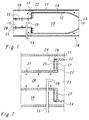
- a secondary combustion chamber is shown in a simplified longitudinal section, which is known from EP-A1 0 669 500, and which is preferred for implementation the invention is suitable.
- the combustion chamber 10 includes a combustion zone 23, which of an inner wall extending in the axial direction 12 and a radial inner wall 17 is limited.
- the inflow zone 20 is delimited by an inner wall 15. Protrudes into the inflow zone 20 a fuel lance 18 from the side, a nozzle at the front end 19 for fuel injection.
- the inner walls 12, 15 and 17 are from an outer wall 11 extending in the axial direction.
- a cooling air duct 14 remains free through the inner wall 12 and the outer wall 11 which cooling air against the flow direction of the hot gases in between the inner wall 15 and the outer wall 11 formed extended space 16 streams.
- the inner wall 12 is convectively cooled by the cooling air.
- the cooling air flows from the space 16 through openings 21 in the inner wall 15 into the inflow zone 20, and through openings 22 in the inner wall 17 into the combustion zone 23, and thereby effects an effusion cooling.
- a Helmholtz resonator arrangement can be integrated, which is simultaneously an effective Cooling of the inner wall 17 ensured.
- On the outside of the radial inner wall 17 is a perforated plate according to FIG. 2 at a distance (A in FIG. 3) 24 arranged in parallel, together with the radial inner wall 17 (Ring-shaped) damping volume 26 includes.
- the inner wall 17 has one A plurality of more or less regularly distributed openings 27, the identical to the openings 22 for the effusion cooling in the combustion chamber 1 can be, but also different geometric dimensions can have.
- the as through holes with a diameter D1 and Length B (Fig. 3) trained openings 27 each act as a damping tube of a Helmholtz partial resonator, which emerges from the respective opening 27 and the underlying partial volume of the damping volume 26 is formed.
- the total damping volume 26 and the entirety of the openings 27 can be understood as individual Helmholtz resonators, their individual damping volumes are interconnected to form the damping volume 26.
- the perforated plate 24 has two more besides the limitation of the damping volume important tasks.
- the openings 25 provided in the perforated plate 24 allow cooling air to flow into the damping volume 26 from the space 16.
- the incoming cooling air cools the Helmholtz resonator arrangement.
- the openings 25 are relative to the openings 27 offset or arranged "on gap". This hits the damping volume 26 incoming cooling air on the opposite of the openings 25 Outside of the inner wall 17, resulting in an effective impingement cooling of the inner wall 17 leads.
- the diameter D2 of the openings 25 (FIG. 3) is opposite the diameter D1 is comparatively small. This ensures that the cooling air flowing through suffers a sufficient pressure drop.
- the resonance frequency of the resonator arrangement or the partial resonators is in the essentially by the distance A, the thickness B of the inner wall 17 or the length of the openings 27, the diameter of the openings 27 and the periodic Distance L (Fig. 3) of the openings 27 is determined.
- the openings 27 are through holes with a length B of a few millimeters and a diameter D1 of a few Millimeters.
- the periodic distance L between neighboring ones Openings 27 are a few millimeters, and the distance A of the perforated plate 24 of the inner wall 17 is also a few millimeters.
- FIGS. 4 and 5 The damping behavior of the individual for the values from the table Partial resonators is shown in FIGS. 4 and 5.
- Fig. 4 shows the relative attenuation power over frequency.
- Fig. 5 shows the displacement amplitude in the damping tube (Opening 27) above the frequency. It can be seen that both curves are pronounced Have maximum at the desired frequency of 5500 Hz.
- the resonator arrangement according to FIGS. 2 and 3 requires a cooling air flow that is large enough to withstand a heat-related deviation of the resonance frequency from the prevent constructively determined value. Such a flow of cooling air is in everyone Case sufficient for cooling the inner wall 17.
- the damping capacity of the single opening 27 is large enough to dampen the overall arrangement to extend to a wider frequency range. A certain amount can do this Scattering range for the values A, B, D1 and L can be chosen to be different Realize resonance frequencies of the individual partial resonators.
- the length of the Openings 25 are not important as long as the pressure drop across them Openings are sufficiently large.
- the invention results in a combustion chamber which, with good acoustic Damping ensures efficient cooling of the inner walls and at the same time can be made compact. It goes without saying that the Helmholtz resonator arrangement in the context of the invention also on others Place of the inner walls can be arranged.
Landscapes
- Engineering & Computer Science (AREA)
- Chemical & Material Sciences (AREA)
- Combustion & Propulsion (AREA)
- Mechanical Engineering (AREA)
- General Engineering & Computer Science (AREA)
- Physics & Mathematics (AREA)
- Acoustics & Sound (AREA)
- Multimedia (AREA)
- Turbine Rotor Nozzle Sealing (AREA)
Claims (5)
- Chambre de combustion (10) pour une turbine à gaz,caractérisée en ce quedans laquelle chambre de combustion (10) les gaz de combustion chauds d'une zone de combustion (23) sont entourés par des parois internes (12, 17) qui sont refroidies par de l'air de refroidissement apporté à l'extérieur des parois internes (12, 17),une plaque à trous (24) s'étendant essentiellement parallèlement aux parois internes (12, 17) et espacée des parois internes (12, 17) étant disposée au moins dans une région partielle du côté extérieur des parois internes (12, 17), laquelle forme, conjointement avec la paroi interne associée (17) un volume d'amortissement fermé (26),la paroi interne (17) présentant, dans la région du volume d'amortissement (26), une pluralité de premières ouvertures (27) disposées de manière répartie, par lesquelles le volume d'amortissement (26) est connecté à la zone de combustion (23) de la chambre de combustion (10),la plaque à trous (24) présentant une pluralité de deuxièmes ouvertures (25) disposées de manière répartie, par lesquelles de l'air de refroidissement entre depuis l'extérieur dans le volume d'amortissement (26) et frappe, à la manière d'un refroidissement par impact entre les premières ouvertures (27), le côté extérieur opposé de la paroi interne (17), etles premières ouvertures (27) conjointement avec le volume d'amortissement (26) formant une pluralité de résonateurs Helmholtz connectés les uns aux autres et agissant en tant qu'amortisseurs sonores des vibrations acoustiques se produisant dans la chambre de combustion,les dimensions géométriques (B, D1) des premières ouvertures individuelles (27) et/oula distance entre la plaque à trous (24) et la paroi interne (17) dans la région des premières ouvertures individuelles (27) et/oula distance périodique (L) des premières ouvertures individuelles (27) les unes aux autres sont sélectionnées essentiellement égales les unes aux autres ou différentes dans une plage de valeurs, pour la production d'une bande de fréquence d'amortissement élargie.
- Chambre de combustion selon la revendication 1, caractérisée en ce que pour l'amortissement de fréquences dans la plage de plusieurs kHz, les premières ouvertures (27) sont réalisées en tant qu'alésages traversants avec une longueur (B) de quelques millimètres et un diamètre (D1) de quelques millimètres, en ce que la distance périodique (L) entre les premières ouvertures voisines (27) est de quelques millimètres, et en ce que la distance (A) de la plaque à trous (24) à la paroi interne (17) est également de quelques millimètres.
- Chambre de combustion selon la revendication 2, caractérisée en ce que pour l'amortissement de fréquences d'environ 5500 Hz, la longueur (B) des premières ouvertures (27) est d'environ 5 mm, le diamètre (D1) des premières ouvertures (27) est d'environ 4,3 mm, la distance périodique (L) des premières ouvertures (27) les unes aux autres est d'environ 10 mm et la distance (A) entre la plaque à trous (24) et la paroi interne (17) est d'environ 5 mm.
- Chambre de combustion selon l'une quelconque des revendications 2 et 3, caractérisée en ce que le diamètre (D2) des deuxièmes ouvertures est inférieur à 1 mm, en particulier est d'environ 0,7 mm.
- Chambre de combustion selon l'une quelconque des revendications 1 à 4, caractérisée en ce que la chambre de combustion (10) est réalisée en tant que chambre de combustion secondaire, en ce que la chambre de combustion (10) est divisée en la zone de combustion (23) et une zone d'afflux (20) disposée en amont, en ce que la zone d'afflux (20) s'élargit dans une transition échelonnée jusqu'à la zone de combustion (23), en ce que la zone de combustion (23) dans la région de la transition échelonnée est limitée par une paroi interne radiale (17), et en ce que la plaque à trous (24) est disposée du côté extérieur de la paroi interne radiale (17).
Priority Applications (2)
| Application Number | Priority Date | Filing Date | Title |
|---|---|---|---|
| EP98810656A EP0971172B1 (fr) | 1998-07-10 | 1998-07-10 | Chambre de combustion pour turbine à gaz avec paroi à structure silencieuse |
| DE59810343T DE59810343D1 (de) | 1998-07-10 | 1998-07-10 | Brennkammer für eine Gasturbine mit schalldämpfender Wandstruktur |
Applications Claiming Priority (1)
| Application Number | Priority Date | Filing Date | Title |
|---|---|---|---|
| EP98810656A EP0971172B1 (fr) | 1998-07-10 | 1998-07-10 | Chambre de combustion pour turbine à gaz avec paroi à structure silencieuse |
Publications (2)
| Publication Number | Publication Date |
|---|---|
| EP0971172A1 EP0971172A1 (fr) | 2000-01-12 |
| EP0971172B1 true EP0971172B1 (fr) | 2003-12-03 |
Family
ID=8236187
Family Applications (1)
| Application Number | Title | Priority Date | Filing Date |
|---|---|---|---|
| EP98810656A Expired - Lifetime EP0971172B1 (fr) | 1998-07-10 | 1998-07-10 | Chambre de combustion pour turbine à gaz avec paroi à structure silencieuse |
Country Status (2)
| Country | Link |
|---|---|
| EP (1) | EP0971172B1 (fr) |
| DE (1) | DE59810343D1 (fr) |
Cited By (2)
| Publication number | Priority date | Publication date | Assignee | Title |
|---|---|---|---|---|
| US7424804B2 (en) | 2003-03-07 | 2008-09-16 | Alstom Technology Ltd | Premix burner |
| EP2559942A1 (fr) | 2011-08-19 | 2013-02-20 | Rolls-Royce Deutschland Ltd & Co KG | Tête de chambre de combustion d'une turbine à gaz dotée d'un refroidissement et d'un amortissement |
Families Citing this family (16)
| Publication number | Priority date | Publication date | Assignee | Title |
|---|---|---|---|---|
| US6351947B1 (en) * | 2000-04-04 | 2002-03-05 | Abb Alstom Power (Schweiz) | Combustion chamber for a gas turbine |
| DE60135436D1 (de) * | 2001-01-09 | 2008-10-02 | Mitsubishi Heavy Ind Ltd | Gasturbinenbrennkammer |
| EP1342953A1 (fr) * | 2002-03-07 | 2003-09-10 | Siemens Aktiengesellschaft | Turbine à gaz |
| GB2390150A (en) | 2002-06-26 | 2003-12-31 | Alstom | Reheat combustion system for a gas turbine including an accoustic screen |
| US6964170B2 (en) | 2003-04-28 | 2005-11-15 | Pratt & Whitney Canada Corp. | Noise reducing combustor |
| EP1623104A1 (fr) * | 2003-05-15 | 2006-02-08 | Alstom Technology Ltd | Dispositif d'isolation phonique dans un canal d'ecoulement |
| GB0425794D0 (en) | 2004-11-24 | 2004-12-22 | Rolls Royce Plc | Acoustic damper |
| DE102006026969A1 (de) | 2006-06-09 | 2007-12-13 | Rolls-Royce Deutschland Ltd & Co Kg | Gasturbinenbrennkammerwand für eine mager-brennende Gasturbinenbrennkammer |
| DE102009032277A1 (de) | 2009-07-08 | 2011-01-20 | Rolls-Royce Deutschland Ltd & Co Kg | Brennkammerkopf einer Gasturbine |
| CH703357A1 (de) | 2010-06-25 | 2011-12-30 | Alstom Technology Ltd | Wärmebelastetes, gekühltes bauteil. |
| CA2907119A1 (fr) * | 2013-03-15 | 2014-12-11 | President And Fellows Of Harvard College | Structures vides a motif repetitif d'ouvertures allongees |
| CN105555517B (zh) | 2013-03-15 | 2018-09-21 | 哈佛大学校长及研究员协会 | 低孔隙率拉胀片材 |
| CN108472915B (zh) | 2015-01-09 | 2021-07-27 | 哈佛大学校董委员会 | 零孔隙率npr结构以及特定位置的npr结构的调整 |
| JP2018510319A (ja) | 2015-01-09 | 2018-04-12 | プレジデント アンド フェローズ オブ ハーバード カレッジ | 負のポアソン比のワッフル状構造体 |
| CA2973363A1 (fr) | 2015-01-09 | 2016-07-14 | President And Fellows Of Harvard College | Structures auxetiques a vide et alveole hyrbrides ayant des motifs mis au point pour un comportement npr pesonnalise |
| JP7012085B2 (ja) * | 2017-07-28 | 2022-01-27 | イビデン株式会社 | 吸音部材、車両用部品及び自動車 |
Family Cites Families (8)
| Publication number | Priority date | Publication date | Assignee | Title |
|---|---|---|---|---|
| FR2191025B1 (fr) * | 1972-07-04 | 1975-03-07 | Aerospatiale | |
| US4199936A (en) * | 1975-12-24 | 1980-04-29 | The Boeing Company | Gas turbine engine combustion noise suppressor |
| FR2447069A1 (fr) * | 1979-01-16 | 1980-08-14 | Westeel Guy | Perfectionnements aux dispositifs d'insonorisation disposes dans des ecoulements fluides |
| DE3318863A1 (de) * | 1983-05-25 | 1984-12-13 | Erich 8480 Weiden Bielefeldt | Kraftmaschine mit gasturbine |
| DE3700444A1 (de) * | 1987-01-09 | 1988-07-21 | Siegfried W Schilling | Heizkessel |
| EP0576717A1 (fr) * | 1992-07-03 | 1994-01-05 | Abb Research Ltd. | Chambre de combustion de turbine à gaz |
| US5528904A (en) * | 1994-02-28 | 1996-06-25 | Jones; Charles R. | Coated hot gas duct liner |
| GB9623615D0 (en) * | 1996-11-13 | 1997-07-09 | Rolls Royce Plc | Jet pipe liner |
-
1998
- 1998-07-10 DE DE59810343T patent/DE59810343D1/de not_active Expired - Lifetime
- 1998-07-10 EP EP98810656A patent/EP0971172B1/fr not_active Expired - Lifetime
Cited By (2)
| Publication number | Priority date | Publication date | Assignee | Title |
|---|---|---|---|---|
| US7424804B2 (en) | 2003-03-07 | 2008-09-16 | Alstom Technology Ltd | Premix burner |
| EP2559942A1 (fr) | 2011-08-19 | 2013-02-20 | Rolls-Royce Deutschland Ltd & Co KG | Tête de chambre de combustion d'une turbine à gaz dotée d'un refroidissement et d'un amortissement |
Also Published As
| Publication number | Publication date |
|---|---|
| EP0971172A1 (fr) | 2000-01-12 |
| DE59810343D1 (de) | 2004-01-15 |
Similar Documents
| Publication | Publication Date | Title |
|---|---|---|
| EP0971172B1 (fr) | Chambre de combustion pour turbine à gaz avec paroi à structure silencieuse | |
| EP0985882B1 (fr) | Amortissement des vibrations dans des combusteurs | |
| EP1336800B1 (fr) | Procédé de réduction des oscillations induites par la combustion dans les dispositifs de combustion ainsi que brûleur à prémélange pour la mise en oeuvre du procédé | |
| EP1423645B1 (fr) | Ensemble amortisseur concu pour reduire les pulsations d'une chambre de combustion dans une installation de turbine a gaz | |
| DE10058688B4 (de) | Dämpferanordnung zur Reduktion von Brennkammerpulsationen | |
| DE4316475C2 (de) | Gasturbinen-Brennkammer | |
| DE60105531T2 (de) | Gasturbinenbrennkammer, Gasturbine und Düsentriebwerk | |
| EP2559942A1 (fr) | Tête de chambre de combustion d'une turbine à gaz dotée d'un refroidissement et d'un amortissement | |
| EP1004823B1 (fr) | Dispositif d'amortissement pour la réduction de l'amplitude d'oscillation d'ondes acoustiques pour un brûleur | |
| DE10325691A1 (de) | Wiederaufheizverbrennungssystem für eine Gasturbine | |
| EP1483536B1 (fr) | Turbine a gaz | |
| CH680523A5 (fr) | ||
| DE4009196A1 (de) | Flammenhalter fuer einen gasturbinentriebwerks-nachbrenner | |
| EP2423597B1 (fr) | Brûleur à prémélange pour une turbine à gaz | |
| EP0990851B1 (fr) | Chambre de combustion pour une turbine à gaz | |
| EP0892217B1 (fr) | Dispositif d'atténuation des vibrations d'une chambre de combustion | |
| DE102008016931A1 (de) | System zur Reduktion der Brennkammerdynamik | |
| EP1048898B1 (fr) | Brûleur | |
| DE19948674B4 (de) | Verbrennungseinrichtung, insbesondere für den Antrieb von Gasturbinen | |
| DE112019004946B4 (de) | Brennerkomponente, Brenner, Gasturbine und Herstellungsverfahren für Brennerkomponente | |
| DE102004010620B4 (de) | Brennkammer zur wirksamen Nutzung von Kühlluft zur akustischen Dämpfung von Brennkammerpulsation | |
| EP1605209B1 (fr) | Chambre de combustion avec dispositif d'amortissement des vibrations thermo-acoustiques | |
| DE60225411T2 (de) | Flammrohr oder Bekleidung für die Brennkammer einer Gasturbine mit niedriger Schadstoffemission | |
| EP2187125A1 (fr) | Dispositif et procédé destinés à l'amortissement d'oscillations de combustion | |
| EP0892216B1 (fr) | Structure de paroi de chambre de combustion absorbant les vibrations |
Legal Events
| Date | Code | Title | Description |
|---|---|---|---|
| PUAI | Public reference made under article 153(3) epc to a published international application that has entered the european phase |
Free format text: ORIGINAL CODE: 0009012 |
|
| AK | Designated contracting states |
Kind code of ref document: A1 Designated state(s): DE GB |
|
| AX | Request for extension of the european patent |
Free format text: AL;LT;LV;MK;RO;SI |
|
| 17P | Request for examination filed |
Effective date: 20000510 |
|
| RAP1 | Party data changed (applicant data changed or rights of an application transferred) |
Owner name: ABB ALSTOM POWER (SCHWEIZ) AG |
|
| AKX | Designation fees paid |
Free format text: DE GB |
|
| RAP1 | Party data changed (applicant data changed or rights of an application transferred) |
Owner name: ALSTOM |
|
| 17Q | First examination report despatched |
Effective date: 20020917 |
|
| RAP1 | Party data changed (applicant data changed or rights of an application transferred) |
Owner name: ALSTOM (SWITZERLAND) LTD |
|
| GRAH | Despatch of communication of intention to grant a patent |
Free format text: ORIGINAL CODE: EPIDOS IGRA |
|
| GRAS | Grant fee paid |
Free format text: ORIGINAL CODE: EPIDOSNIGR3 |
|
| GRAA | (expected) grant |
Free format text: ORIGINAL CODE: 0009210 |
|
| AK | Designated contracting states |
Kind code of ref document: B1 Designated state(s): DE GB |
|
| REG | Reference to a national code |
Ref country code: GB Ref legal event code: FG4D Free format text: NOT ENGLISH |
|
| RAP2 | Party data changed (patent owner data changed or rights of a patent transferred) |
Owner name: ALSTOM TECHNOLOGY LTD |
|
| REF | Corresponds to: |
Ref document number: 59810343 Country of ref document: DE Date of ref document: 20040115 Kind code of ref document: P |
|
| GBT | Gb: translation of ep patent filed (gb section 77(6)(a)/1977) |
Effective date: 20040225 |
|
| PLBE | No opposition filed within time limit |
Free format text: ORIGINAL CODE: 0009261 |
|
| STAA | Information on the status of an ep patent application or granted ep patent |
Free format text: STATUS: NO OPPOSITION FILED WITHIN TIME LIMIT |
|
| 26N | No opposition filed |
Effective date: 20040906 |
|
| PGFP | Annual fee paid to national office [announced via postgrant information from national office to epo] |
Ref country code: GB Payment date: 20110622 Year of fee payment: 14 |
|
| PGFP | Annual fee paid to national office [announced via postgrant information from national office to epo] |
Ref country code: DE Payment date: 20110729 Year of fee payment: 14 |
|
| GBPC | Gb: european patent ceased through non-payment of renewal fee |
Effective date: 20120710 |
|
| PG25 | Lapsed in a contracting state [announced via postgrant information from national office to epo] |
Ref country code: GB Free format text: LAPSE BECAUSE OF NON-PAYMENT OF DUE FEES Effective date: 20120710 Ref country code: DE Free format text: LAPSE BECAUSE OF NON-PAYMENT OF DUE FEES Effective date: 20130201 |
|
| REG | Reference to a national code |
Ref country code: DE Ref legal event code: R119 Ref document number: 59810343 Country of ref document: DE Effective date: 20130201 |