EP0971172B1 - Gas turbine combustion chamber with silencing wall structure - Google Patents
Gas turbine combustion chamber with silencing wall structure Download PDFInfo
- Publication number
- EP0971172B1 EP0971172B1 EP98810656A EP98810656A EP0971172B1 EP 0971172 B1 EP0971172 B1 EP 0971172B1 EP 98810656 A EP98810656 A EP 98810656A EP 98810656 A EP98810656 A EP 98810656A EP 0971172 B1 EP0971172 B1 EP 0971172B1
- Authority
- EP
- European Patent Office
- Prior art keywords
- combustion chamber
- orifices
- wall
- damping
- perforated plate
- Prior art date
- Legal status (The legal status is an assumption and is not a legal conclusion. Google has not performed a legal analysis and makes no representation as to the accuracy of the status listed.)
- Expired - Lifetime
Links
- 238000002485 combustion reaction Methods 0.000 title claims description 67
- 230000030279 gene silencing Effects 0.000 title 1
- 238000013016 damping Methods 0.000 claims description 39
- 238000001816 cooling Methods 0.000 claims description 34
- 239000007789 gas Substances 0.000 claims description 16
- 230000000737 periodic effect Effects 0.000 claims description 11
- 230000007704 transition Effects 0.000 claims description 5
- 238000011144 upstream manufacturing Methods 0.000 claims description 3
- 230000010355 oscillation Effects 0.000 claims description 2
- 239000000567 combustion gas Substances 0.000 claims 1
- 239000000446 fuel Substances 0.000 description 6
- 239000000243 solution Substances 0.000 description 3
- 238000006073 displacement reaction Methods 0.000 description 2
- 238000010276 construction Methods 0.000 description 1
- 230000000694 effects Effects 0.000 description 1
- 238000002347 injection Methods 0.000 description 1
- 239000007924 injection Substances 0.000 description 1
- 230000002265 prevention Effects 0.000 description 1
Images


Classifications
-
- F—MECHANICAL ENGINEERING; LIGHTING; HEATING; WEAPONS; BLASTING
- F02—COMBUSTION ENGINES; HOT-GAS OR COMBUSTION-PRODUCT ENGINE PLANTS
- F02M—SUPPLYING COMBUSTION ENGINES IN GENERAL WITH COMBUSTIBLE MIXTURES OR CONSTITUENTS THEREOF
- F02M35/00—Combustion-air cleaners, air intakes, intake silencers, or induction systems specially adapted for, or arranged on, internal-combustion engines
- F02M35/12—Intake silencers ; Sound modulation, transmission or amplification
- F02M35/1255—Intake silencers ; Sound modulation, transmission or amplification using resonance
- F02M35/1261—Helmholtz resonators
-
- F—MECHANICAL ENGINEERING; LIGHTING; HEATING; WEAPONS; BLASTING
- F01—MACHINES OR ENGINES IN GENERAL; ENGINE PLANTS IN GENERAL; STEAM ENGINES
- F01N—GAS-FLOW SILENCERS OR EXHAUST APPARATUS FOR MACHINES OR ENGINES IN GENERAL; GAS-FLOW SILENCERS OR EXHAUST APPARATUS FOR INTERNAL COMBUSTION ENGINES
- F01N1/00—Silencing apparatus characterised by method of silencing
- F01N1/02—Silencing apparatus characterised by method of silencing by using resonance
- F01N1/023—Helmholtz resonators
-
- F—MECHANICAL ENGINEERING; LIGHTING; HEATING; WEAPONS; BLASTING
- F02—COMBUSTION ENGINES; HOT-GAS OR COMBUSTION-PRODUCT ENGINE PLANTS
- F02B—INTERNAL-COMBUSTION PISTON ENGINES; COMBUSTION ENGINES IN GENERAL
- F02B77/00—Component parts, details or accessories, not otherwise provided for
- F02B77/11—Thermal or acoustic insulation
- F02B77/13—Acoustic insulation
-
- F—MECHANICAL ENGINEERING; LIGHTING; HEATING; WEAPONS; BLASTING
- F23—COMBUSTION APPARATUS; COMBUSTION PROCESSES
- F23M—CASINGS, LININGS, WALLS OR DOORS SPECIALLY ADAPTED FOR COMBUSTION CHAMBERS, e.g. FIREBRIDGES; DEVICES FOR DEFLECTING AIR, FLAMES OR COMBUSTION PRODUCTS IN COMBUSTION CHAMBERS; SAFETY ARRANGEMENTS SPECIALLY ADAPTED FOR COMBUSTION APPARATUS; DETAILS OF COMBUSTION CHAMBERS, NOT OTHERWISE PROVIDED FOR
- F23M20/00—Details of combustion chambers, not otherwise provided for, e.g. means for storing heat from flames
- F23M20/005—Noise absorbing means
-
- F—MECHANICAL ENGINEERING; LIGHTING; HEATING; WEAPONS; BLASTING
- F23—COMBUSTION APPARATUS; COMBUSTION PROCESSES
- F23R—GENERATING COMBUSTION PRODUCTS OF HIGH PRESSURE OR HIGH VELOCITY, e.g. GAS-TURBINE COMBUSTION CHAMBERS
- F23R3/00—Continuous combustion chambers using liquid or gaseous fuel
- F23R3/002—Wall structures
-
- G—PHYSICS
- G10—MUSICAL INSTRUMENTS; ACOUSTICS
- G10K—SOUND-PRODUCING DEVICES; METHODS OR DEVICES FOR PROTECTING AGAINST, OR FOR DAMPING, NOISE OR OTHER ACOUSTIC WAVES IN GENERAL; ACOUSTICS NOT OTHERWISE PROVIDED FOR
- G10K11/00—Methods or devices for transmitting, conducting or directing sound in general; Methods or devices for protecting against, or for damping, noise or other acoustic waves in general
- G10K11/16—Methods or devices for protecting against, or for damping, noise or other acoustic waves in general
- G10K11/162—Selection of materials
- G10K11/168—Plural layers of different materials, e.g. sandwiches
-
- G—PHYSICS
- G10—MUSICAL INSTRUMENTS; ACOUSTICS
- G10K—SOUND-PRODUCING DEVICES; METHODS OR DEVICES FOR PROTECTING AGAINST, OR FOR DAMPING, NOISE OR OTHER ACOUSTIC WAVES IN GENERAL; ACOUSTICS NOT OTHERWISE PROVIDED FOR
- G10K11/00—Methods or devices for transmitting, conducting or directing sound in general; Methods or devices for protecting against, or for damping, noise or other acoustic waves in general
- G10K11/16—Methods or devices for protecting against, or for damping, noise or other acoustic waves in general
- G10K11/172—Methods or devices for protecting against, or for damping, noise or other acoustic waves in general using resonance effects
-
- F—MECHANICAL ENGINEERING; LIGHTING; HEATING; WEAPONS; BLASTING
- F01—MACHINES OR ENGINES IN GENERAL; ENGINE PLANTS IN GENERAL; STEAM ENGINES
- F01N—GAS-FLOW SILENCERS OR EXHAUST APPARATUS FOR MACHINES OR ENGINES IN GENERAL; GAS-FLOW SILENCERS OR EXHAUST APPARATUS FOR INTERNAL COMBUSTION ENGINES
- F01N2490/00—Structure, disposition or shape of gas-chambers
- F01N2490/15—Plurality of resonance or dead chambers
- F01N2490/155—Plurality of resonance or dead chambers being disposed one after the other in flow direction
-
- F—MECHANICAL ENGINEERING; LIGHTING; HEATING; WEAPONS; BLASTING
- F05—INDEXING SCHEMES RELATING TO ENGINES OR PUMPS IN VARIOUS SUBCLASSES OF CLASSES F01-F04
- F05B—INDEXING SCHEME RELATING TO WIND, SPRING, WEIGHT, INERTIA OR LIKE MOTORS, TO MACHINES OR ENGINES FOR LIQUIDS COVERED BY SUBCLASSES F03B, F03D AND F03G
- F05B2260/00—Function
- F05B2260/20—Heat transfer, e.g. cooling
- F05B2260/201—Heat transfer, e.g. cooling by impingement of a fluid
-
- F—MECHANICAL ENGINEERING; LIGHTING; HEATING; WEAPONS; BLASTING
- F05—INDEXING SCHEMES RELATING TO ENGINES OR PUMPS IN VARIOUS SUBCLASSES OF CLASSES F01-F04
- F05B—INDEXING SCHEME RELATING TO WIND, SPRING, WEIGHT, INERTIA OR LIKE MOTORS, TO MACHINES OR ENGINES FOR LIQUIDS COVERED BY SUBCLASSES F03B, F03D AND F03G
- F05B2260/00—Function
- F05B2260/96—Preventing, counteracting or reducing vibration or noise
-
- F—MECHANICAL ENGINEERING; LIGHTING; HEATING; WEAPONS; BLASTING
- F23—COMBUSTION APPARATUS; COMBUSTION PROCESSES
- F23R—GENERATING COMBUSTION PRODUCTS OF HIGH PRESSURE OR HIGH VELOCITY, e.g. GAS-TURBINE COMBUSTION CHAMBERS
- F23R2900/00—Special features of, or arrangements for continuous combustion chambers; Combustion processes therefor
- F23R2900/00014—Reducing thermo-acoustic vibrations by passive means, e.g. by Helmholtz resonators
Definitions
- the present invention relates to the field of gas turbines. It affects a combustion chamber for a gas turbine according to the preamble of claim 1.
- Gas turbines can cause pressure vibrations during operation under certain conditions or acoustic vibrations that occur in terms of frequency Range of several kHz, e.g. 1.8 kHz or around 5 kHz.
- Vibrations are disruptive to operation and are therefore undesirable.
- a way to dampen or suppress such vibrations consists in providing fluidic means in the combustion chamber, which influence the flow of hot gases in that the acoustic vibrations are not excited or only to a small extent.
- Helmholtz resonators on the combustion chamber attach to the vibrations as damping elements couple and dampen the vibrations or completely to disappear bring.
- a gas turbine combustor is described in US Pat. No. 5,644,918, with the leading within the cooling air surrounding the combustion chamber Double jacket and on the front of the combustion chamber in the area of the burner by pulling in additional dividing walls Helmholtz resonators 48 and 56 are formed, the constrictions 50 and 58 in connection with the combustion chamber stand, but are otherwise completely completed, so that a Flow of cooling air through the resonator rooms does not take place.
- European publication EP-A1-0 576 717 discloses a gas turbine combustor.
- the flame tube is located away from the combustion chamber Side exposed to an air flow supplied by the gas turbine compressor.
- the flame tube is essentially composed of wall parts, the combustion chamber outer wall parts facing away from each have a plurality of inlet openings distributed over the circumference have, introduced via the cooling air into an intermediate space arranged in the flame tube becomes. From the intermediate space, the cooling air is passed through outlet bores into the combustion chamber facing inner wall parts introduced into the combustion chamber.
- the space between the wall parts is on to form a Helmholtz resonator large, closed additional volume coupled, with the inlet openings in the outer wall parts as feed pipes and the outlet bores as damping pipes of the Helmholtz resonator, are formed.
- the object is achieved in a combustion chamber of the type mentioned in that the geometric dimensions of the individual first openings and / or the distance between Perforated plate and inner wall in the area of the individual first openings and / or the periodic spacing of the individual first openings from one another to produce a broadened damping frequency band with each other substantially the same or within of a range of values can be selected differently.
- the invention is therefore based on an embodiment in which a plurality of interconnected ones Helmholtz resonators by arranging two parallel ones Perforated plate can be created. The one perforated plate, the relatively large openings At the same time, the damping tubes of the individual resonators form the inner wall of the Combustion chamber itself.
- the other, outside perforated plate bounds together with the inner wall the intervening, interconnected damping volumes of the individual resonators.
- the relatively small openings on the outside Perforated plate is flowed through by cooling air, which on the one hand the resonators stabilized thermally and frequency and on the other hand by impact highly effective impingement cooling of the inner wall on the outside of the inner wall allows.
- the additional effort to create the resonators exists - if the large openings in the Inner wall already exist - just from attaching the outer one Perforated plate.
- the first embodiment of the combustion chamber according to the invention is characterized in that the geometric dimensions of each first openings and the periodic intervals between the first openings are chosen essentially the same.
- the individual partial resonators are in this case, all tuned to the same damping frequency, so that for the damping arrangement overall a high damping in a relative results in a narrow frequency range.
- the second embodiment of the combustion chamber according to the invention is characterized in that the geometric dimensions of each first openings and / or the distance between the perforated plate and the inner wall in Area of the individual first openings and / or the periodic distance of the individual first openings with each other to produce a widened Damping frequency band selected differently within a range of values become.
- the distribution of values for the individual partial resonators means that the overall arrangement of the frequency range in which a noticeable attenuation takes place, significantly broadened, which is advantageous when the combustion chamber vibrations scatter more in frequency.
- the first openings For common frequency values of combustion chamber vibrations in the range of several kHz are the first openings as through holes with a length of a few millimeters and a diameter of a few millimeters.
- the periodic distance between adjacent first openings is a few millimeters, and the distance of the perforated plate from the inner wall is also a few millimeters.
- the length of the first openings is approximately 5 mm, the Diameter of the first openings about 4.3 mm, the periodic distance of the first openings to each other about 10 mm, and the distance between the Perforated plate and the inner wall about 5 mm.
- the second openings are chosen so small that there is sufficient Pressure drop for the cooling air flowing through results.
- the diameter is preferred the second openings are smaller than 1 mm, in particular approximately 0.7 mm.
- the damping behavior is particularly advantageous if according to another Embodiment the combustion chamber is designed as a secondary combustion chamber, if the combustion chamber is in the combustion zone and an upstream Inflow zone is divided if the inflow zone is in a step-like manner Transition to the combustion zone expanded when the combustion zone in the Area of the step-like transition delimited by a radial inner wall and when the perforated plate is arranged on the outside of the radial inner wall is.
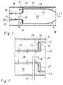
- a secondary combustion chamber is shown in a simplified longitudinal section, which is known from EP-A1 0 669 500, and which is preferred for implementation the invention is suitable.
- the combustion chamber 10 includes a combustion zone 23, which of an inner wall extending in the axial direction 12 and a radial inner wall 17 is limited.
- the inflow zone 20 is delimited by an inner wall 15. Protrudes into the inflow zone 20 a fuel lance 18 from the side, a nozzle at the front end 19 for fuel injection.
- the inner walls 12, 15 and 17 are from an outer wall 11 extending in the axial direction.
- a cooling air duct 14 remains free through the inner wall 12 and the outer wall 11 which cooling air against the flow direction of the hot gases in between the inner wall 15 and the outer wall 11 formed extended space 16 streams.
- the inner wall 12 is convectively cooled by the cooling air.
- the cooling air flows from the space 16 through openings 21 in the inner wall 15 into the inflow zone 20, and through openings 22 in the inner wall 17 into the combustion zone 23, and thereby effects an effusion cooling.
- a Helmholtz resonator arrangement can be integrated, which is simultaneously an effective Cooling of the inner wall 17 ensured.
- On the outside of the radial inner wall 17 is a perforated plate according to FIG. 2 at a distance (A in FIG. 3) 24 arranged in parallel, together with the radial inner wall 17 (Ring-shaped) damping volume 26 includes.
- the inner wall 17 has one A plurality of more or less regularly distributed openings 27, the identical to the openings 22 for the effusion cooling in the combustion chamber 1 can be, but also different geometric dimensions can have.
- the as through holes with a diameter D1 and Length B (Fig. 3) trained openings 27 each act as a damping tube of a Helmholtz partial resonator, which emerges from the respective opening 27 and the underlying partial volume of the damping volume 26 is formed.
- the total damping volume 26 and the entirety of the openings 27 can be understood as individual Helmholtz resonators, their individual damping volumes are interconnected to form the damping volume 26.
- the perforated plate 24 has two more besides the limitation of the damping volume important tasks.
- the openings 25 provided in the perforated plate 24 allow cooling air to flow into the damping volume 26 from the space 16.
- the incoming cooling air cools the Helmholtz resonator arrangement.
- the openings 25 are relative to the openings 27 offset or arranged "on gap". This hits the damping volume 26 incoming cooling air on the opposite of the openings 25 Outside of the inner wall 17, resulting in an effective impingement cooling of the inner wall 17 leads.
- the diameter D2 of the openings 25 (FIG. 3) is opposite the diameter D1 is comparatively small. This ensures that the cooling air flowing through suffers a sufficient pressure drop.
- the resonance frequency of the resonator arrangement or the partial resonators is in the essentially by the distance A, the thickness B of the inner wall 17 or the length of the openings 27, the diameter of the openings 27 and the periodic Distance L (Fig. 3) of the openings 27 is determined.
- the openings 27 are through holes with a length B of a few millimeters and a diameter D1 of a few Millimeters.
- the periodic distance L between neighboring ones Openings 27 are a few millimeters, and the distance A of the perforated plate 24 of the inner wall 17 is also a few millimeters.
- FIGS. 4 and 5 The damping behavior of the individual for the values from the table Partial resonators is shown in FIGS. 4 and 5.
- Fig. 4 shows the relative attenuation power over frequency.
- Fig. 5 shows the displacement amplitude in the damping tube (Opening 27) above the frequency. It can be seen that both curves are pronounced Have maximum at the desired frequency of 5500 Hz.
- the resonator arrangement according to FIGS. 2 and 3 requires a cooling air flow that is large enough to withstand a heat-related deviation of the resonance frequency from the prevent constructively determined value. Such a flow of cooling air is in everyone Case sufficient for cooling the inner wall 17.
- the damping capacity of the single opening 27 is large enough to dampen the overall arrangement to extend to a wider frequency range. A certain amount can do this Scattering range for the values A, B, D1 and L can be chosen to be different Realize resonance frequencies of the individual partial resonators.
- the length of the Openings 25 are not important as long as the pressure drop across them Openings are sufficiently large.
- the invention results in a combustion chamber which, with good acoustic Damping ensures efficient cooling of the inner walls and at the same time can be made compact. It goes without saying that the Helmholtz resonator arrangement in the context of the invention also on others Place of the inner walls can be arranged.
Landscapes
- Engineering & Computer Science (AREA)
- Chemical & Material Sciences (AREA)
- Combustion & Propulsion (AREA)
- Mechanical Engineering (AREA)
- General Engineering & Computer Science (AREA)
- Physics & Mathematics (AREA)
- Acoustics & Sound (AREA)
- Multimedia (AREA)
- Turbine Rotor Nozzle Sealing (AREA)
Description
Die vorliegende Erfindung bezieht sich auf das Gebiet der Gasturbinen. Sie betrifft
eine Brennkammer für eine Gasturbine
gemäss dem Oberbegriff des Anspruchs 1.The present invention relates to the field of gas turbines. It affects
a combustion chamber for a gas turbine
according to the preamble of
In den Brennkammern, insbesondere den Sekundärbrennkammem, herkömmlicher Gasturbinen kann es im Betrieb unter bestimmten Bedingungen zu Druckschwingungen bzw. akustischen Schwingungen kommen, die frequenzmässig im Bereich von mehreren kHz, z.B. 1,8 kHz oder um 5 kHz herum liegen. Derartige Schwingungen erweisen sich als störend für den Betrieb und sind daher unerwünscht. Eine Möglichkeit zur Dämpfung oder Unterdrückung derartiger Schwingungen besteht darin, strömungstechnische Mittel in der Brennkammer vorzusehen, welche die Strömung der heissen Gase dahingehend beeinflussen, dass die akustischen Schwingungen nicht oder nur in geringem Masse angeregt werden. Eine andere Möglichkeit besteht darin, an der Brennkammer sogenannte Helmholtzresonatoren anzubringen, die als Dämpfungselemente an die Schwingungen ankoppeln und die Schwingungen dämpfen oder vollständig zum Verschwinden bringen.More conventional in the combustion chambers, especially the secondary combustion chambers Gas turbines can cause pressure vibrations during operation under certain conditions or acoustic vibrations that occur in terms of frequency Range of several kHz, e.g. 1.8 kHz or around 5 kHz. such Vibrations are disruptive to operation and are therefore undesirable. A way to dampen or suppress such vibrations consists in providing fluidic means in the combustion chamber, which influence the flow of hot gases in that the acoustic vibrations are not excited or only to a small extent. Another possibility is the so-called Helmholtz resonators on the combustion chamber attach to the vibrations as damping elements couple and dampen the vibrations or completely to disappear bring.
Aus dem Stand der Technik sind verschiedene Beispiele für den Einsatz von Helmholtzresonatoren bekannt. In der Druckschrift US-A-5,373,695 wird eine Ringbrennkammer für eine Gasturbine beschrieben, bei welcher an der Stirnseite neben den Brennern einzelne, mit Kühlluft gespülte Helmholtzresonatoren angeordnet sind, die jeweils ein aussenliegendes Dämpfungsvolumen umfassen, das über ein Dämpfungsrohr mit der Brennkammer in Verbindung steht und zur Verhinderung einer hitzebedingten frequenzmässigen Verstimmung über ein dünnes Versorgungsrohr von aussen mit Kühlluft beaufschlagt wird.Various examples of the use of are from the prior art Helmholtz resonators known. In US-A-5,373,695 a Annular combustion chamber for a gas turbine described, in which on the front side individual Helmholtz resonators flushed with cooling air are arranged next to the burners are, each comprising an external damping volume, the is connected to the combustion chamber via a damping tube and for prevention a heat-related frequency detuning over a thin one Cooling air is applied to the supply pipe from the outside.
In der Druckschrift US-A-5,644,918 wird eine Gasturbinen-Brennkammer beschrieben, bei der innerhalb des die Brennkammer umgebenden Kühlluft führenden Doppelmantels und an der Stirnseite der Brennkammer im Bereich der Brenner durch Einziehen zusätzlicher Trennwände Helmholtzresonatoren 48 und 56 gebildet werden, die über Verengungen 50 bzw. 58 mit der Brennkammer in Verbindung stehen, im übrigen aber vollkommen abgeschlossen sind, so dass ein Durchfluss von Kühlluft durch die Resonatorräume nicht stattfindet.A gas turbine combustor is described in US Pat. No. 5,644,918, with the leading within the cooling air surrounding the combustion chamber Double jacket and on the front of the combustion chamber in the area of the burner by pulling in additional dividing walls Helmholtz resonators 48 and 56 are formed, the constrictions 50 and 58 in connection with the combustion chamber stand, but are otherwise completely completed, so that a Flow of cooling air through the resonator rooms does not take place.
Eine andere Lösung, die sich speziell auf eine Sekundärbrennkammer bezieht, ist in der Druckschrift US-A-5, 431,018 dargestellt. Ein mit Kühlluft gespülter Helmholtzresonator umgibt hier konzentrisch die radial in die Brennkammer einmündende Brennstoffleitung, durch welche der Brennstoff für die Nachverbrennung in die Brennkammer eingedüst wird.Another solution that specifically relates to a secondary combustion chamber is in US-A-5, 431,018. A Helmholtz resonator flushed with cooling air surrounds concentrically the one that opens radially into the combustion chamber Fuel line through which the fuel for afterburning in the combustion chamber is injected.
Die bekannten, mit Helmholtzresonatoren arbeitenden Lösungen sind aufwendig in der Konstruktion, lassen sich bei vorhandenen Gasturbinen nur schwer nachrüsten, nehmen, wenn sie in einer Mehrzahl eingesetzt werden, erheblichen Platz ein, und sind nicht kompatibel mit Kühlkonzepten, bei denen die Innenwand der Brennkammer durch von aussen herangeführte Kühlluft gekühlt wird. The known solutions working with Helmholtz resonators are complex in the construction, is difficult to retrofit with existing gas turbines, take up considerable space when used in a plurality a, and are not compatible with cooling concepts where the inner wall of the Combustion chamber is cooled by cooling air brought in from the outside.
Die Europäische Veröffentlichung EP-A1-0 576 717 offenbart eine Gasturbinenbrennkammer. In dieser Brennkammer ist das Flammrohr aus seiner vom Verbrennungsraum abgewandten Seite einem vom Verdichter des Gasturbine gelieferten Luftstrom ausgesetzt. Das Flammrohr setzt sich im wesentlichen aus Wandteilen zusammen, wobei die dem Verbrennungsraum abgewandten äusseren Wandteile jeweils mehrere über den Umfang verteilte Einlassöffnungen aufweisen, über die Kühlluft in einen im Flammrohr angeordneten Zwischenraum eingeleitet wird. Aus den Zwischenraum wird die Kühlluft über Austrittsbohrungen in den dem Verbrennungsraum zugewandten inneren Wandteilen in den Verbrennungsraum eingeleitet. Der Zwischenraum zwischen den Wandteilen ist zwecks Bildung eines Helmholtzresonators an ein grosses, abgeschlossenes Zusatzvolumen angekoppelt, wobei die Einlassöffnungen in den äusseren Wandteilen als Zuführrohre und die Austrittsbohrungen als Dämpfungsrohre des Helmholtzresonators, ausgebildet sind.European publication EP-A1-0 576 717 discloses a gas turbine combustor. In this combustion chamber the flame tube is located away from the combustion chamber Side exposed to an air flow supplied by the gas turbine compressor. The flame tube is essentially composed of wall parts, the combustion chamber outer wall parts facing away from each have a plurality of inlet openings distributed over the circumference have, introduced via the cooling air into an intermediate space arranged in the flame tube becomes. From the intermediate space, the cooling air is passed through outlet bores into the combustion chamber facing inner wall parts introduced into the combustion chamber. The The space between the wall parts is on to form a Helmholtz resonator large, closed additional volume coupled, with the inlet openings in the outer wall parts as feed pipes and the outlet bores as damping pipes of the Helmholtz resonator, are formed.
Es ist daher Aufgabe der Erfindung, eine durch Helmholtzresonatoren akustisch bedämpfte Brennkammer für Gasturbinen zu schaffen, welche die Nachteile der bekannten Lösungen vermeidet und sich insbesondere durch einen geringem zusätzlichen Aufwand und Platzbedarf für die integrierten Resonatoren auszeichnet, und zugleich eine effektive Kühlung der Innenwände der Brennkammer erlaubt.It is therefore an object of the invention to provide an acoustically damped by Helmholtz resonators Combustion chamber for gas turbines to create the disadvantages of the known solutions avoids and especially through a small additional effort and space for the integrated resonators, and at the same time effective cooling of the Internal walls of the combustion chamber allowed.
Die Aufgabe wird bei einer Brennkammer der eingangs genannten Art dadurch gelöst, dass die geometrischen Abmessungen der einzelnen ersten Öffnungen und/oder der Abstand zwischen Lochplatte und Innenwand im Bereich der einzelnen ersten Öffnungen und/oder der periodische Abstand der einzelnen ersten Öffnungen untereinander zur Erzeugung eines verbreiterten Dämpfungsfrequenzbandes untereinander im wesentlichen gleich oder innerhalb eines Wertebereiches unterschiedlich gewählt werden. Die Erfindung geht also von einer Ausführungsform aus, in der eine Mehrzahl von miteinander verbundenen Helmholtzresonatoren durch die Anordnung zweier parallel verlaufenden Lochplatte geschaffen werden. Die eine Lochplatte, deren relativ grosse Öffnungen zugleich die Dämpfungsrohre der Einzelresonatoren bilden, ist die Innenwand der Brennkammer selbst. Die andere, aussenliegende Lochplatte begrenzt zusammen mit der Innenwand die dazwischenliegenden, untereinander verbundenen Dämpfungsvolumina der Einzelresonatoren. Die relativ kleinen Öffnungen der aussenliegenden Lochplatte werden von Kühlluft durchströmt, die einerseits die Resonatoren thermisch und frequenzmässig stabilisiert und andererseits durch Auftreffen auf die Aussenseite der Innenwand eine hochwirksame Prallkühlung der Innenwand ermöglicht. Der zusätzliche Aufwand zur Schaffung der Resonatoren besteht dabei - wenn bei vorhandener Effusionskühlung die grossen Öffnungen in der Innenwand bereits vorhanden sind - lediglich aus dem Anbringen der äusseren Lochplatte.The object is achieved in a combustion chamber of the type mentioned in that the geometric dimensions of the individual first openings and / or the distance between Perforated plate and inner wall in the area of the individual first openings and / or the periodic spacing of the individual first openings from one another to produce a broadened damping frequency band with each other substantially the same or within of a range of values can be selected differently. The invention is therefore based on an embodiment in which a plurality of interconnected ones Helmholtz resonators by arranging two parallel ones Perforated plate can be created. The one perforated plate, the relatively large openings At the same time, the damping tubes of the individual resonators form the inner wall of the Combustion chamber itself. The other, outside perforated plate bounds together with the inner wall the intervening, interconnected damping volumes of the individual resonators. The relatively small openings on the outside Perforated plate is flowed through by cooling air, which on the one hand the resonators stabilized thermally and frequency and on the other hand by impact highly effective impingement cooling of the inner wall on the outside of the inner wall allows. The additional effort to create the resonators exists - if the large openings in the Inner wall already exist - just from attaching the outer one Perforated plate.
Die erste erfindungsgemässe Ausführungsform der Brennkammer ist dadurch gekennzeichnet, dass die geometrischen Abmessungen der einzelnen ersten Oeffnungen und die periodischen Abstände der ersten Oeffnungen untereinander im wesentlichen gleich gewählt sind. Die einzelnen Teilresonatoren sind in diesem Fall alle auf dieselbe Dämpfungsfrequenz abgestimmt, so dass sich für die Dämpfungsanordnung insgesamt eine hohe Dämpfung in einem relativ schmalen Frequenzbereich ergibt.The first embodiment of the combustion chamber according to the invention is characterized in that the geometric dimensions of each first openings and the periodic intervals between the first openings are chosen essentially the same. The individual partial resonators are in this case, all tuned to the same damping frequency, so that for the damping arrangement overall a high damping in a relative results in a narrow frequency range.
Die zweite erfindungsgemässe Ausführungsform der Brennkammer zeichnet sich dadurch aus, dass die geometrischen Abmessungen der einzelnen ersten Öffnungen und/oder der Abstand zwischen Lochplatte und Innenwand im Bereich der einzelnen ersten Öffnungen und/oder der periodische Abstand der einzelnen ersten Öffnungen untereinander zur Erzeugung eines verbreiterten Dämpfungsfrequenzbandes innerhalb eines Wertebereiches unterschiedlich gewählt werden. Durch die Wertestreuung für die einzelnen Teilresonatoren wird für die Gesamtanordnung der Frequenzbereich, in welchem eine merkliche Dämpfun stattfindet, deutlich verbreitert, was vorteilhaft ist, wenn die Brennkammerschwingungen in der Frequenz stärker streuen.The second embodiment of the combustion chamber according to the invention is characterized in that the geometric dimensions of each first openings and / or the distance between the perforated plate and the inner wall in Area of the individual first openings and / or the periodic distance of the individual first openings with each other to produce a widened Damping frequency band selected differently within a range of values become. The distribution of values for the individual partial resonators means that the overall arrangement of the frequency range in which a noticeable attenuation takes place, significantly broadened, which is advantageous when the combustion chamber vibrations scatter more in frequency.
Für übliche Frequenzwerte der Brennkammerschwingungen im Bereich von mehreren kHz sind die ersten Öffnungen als Durchgangsbohrungen mit einer Länge von wenigen Millimetern und einem Durchmesser von wenigen Millimetern ausgebildet. Der periodische Abstand zwischen benachbarten ersten Öffnungen beträgt wenige Millimeter, und der Abstand der Lochplatte von der Innenwand beträgt ebenfalls wenige Millimeter. Insbesondere betragen zur Dämpfung von Frequenzen von etwa 5500 Hz die Länge der ersten Öffnungen etwa 5 mm, der Durchmesser der ersten Öffnungen etwa 4,3 mm, der periodische Abstand der ersten Öffnungen untereinander etwa 10 mm, und der Abstand zwischen der Lochplatte und der Innenwand etwa 5 mm.For common frequency values of combustion chamber vibrations in the range of several kHz are the first openings as through holes with a length of a few millimeters and a diameter of a few millimeters. The periodic distance between adjacent first openings is a few millimeters, and the distance of the perforated plate from the inner wall is also a few millimeters. In particular, to attenuate frequencies of approximately 5500 Hz the length of the first openings is approximately 5 mm, the Diameter of the first openings about 4.3 mm, the periodic distance of the first openings to each other about 10 mm, and the distance between the Perforated plate and the inner wall about 5 mm.
Die zweiten Öffnungen werden so klein gewählt, dass sich ein ausreichender Druckabfall für die durchströmende Kühlluft ergibt. Bevorzugt ist der Durchmesser der zweiten Öffnungen kleiner als 1 mm, insbesondere etwa 0,7 mm.The second openings are chosen so small that there is sufficient Pressure drop for the cooling air flowing through results. The diameter is preferred the second openings are smaller than 1 mm, in particular approximately 0.7 mm.
Besonders vorteilhaft ist das Dämpfungsverhalten, wenn gemäss einer weiteren Ausführungsform die Brennkammer als Sekundärbrennkammer ausgebildet ist, wenn die Brennkammer in die Verbrennungszone und eine stromaufwärts angeordnete Zuströmzone unterteilt ist, wenn die Zuströmzone sich in einem stufenartigen Übergang zur Verbrennungszone erweitert, wenn die Verbrennungszone im Bereich des stufenartigen Übergangs durch eine radiale Innenwand begrenzt wird, und wenn die Lochplatte an der Aussenseite der radialen Innenwand angeordnet ist. The damping behavior is particularly advantageous if according to another Embodiment the combustion chamber is designed as a secondary combustion chamber, if the combustion chamber is in the combustion zone and an upstream Inflow zone is divided if the inflow zone is in a step-like manner Transition to the combustion zone expanded when the combustion zone in the Area of the step-like transition delimited by a radial inner wall and when the perforated plate is arranged on the outside of the radial inner wall is.
Die Erfindung soll nachfolgend anhand von Ausführungsbeispielen im Zusammenhang mit der Zeichnung näher erläutert werden. Es zeigen
- Fig. 1
- im vereinfachten Längsschnitt eine Sekundärbrennkammer, wie sie aus dem Stand der Technik, insbesondere der EP-A1 0 669 500, bekannt ist;
- Fig. 2
- einen vergrösserten Ausschnitt der Brennkammer nach Fig. 1 im Bereich des stufenartigen Übergangs zwischen Zuströmzone und Verbrennungszone mit einer integrierten Helmholtzresonator-Anordnung gemäss einem bevorzugten Ausführungsbeispiel der Erfindung;
- Fig. 3
- in einer perspektivischen, vergrösserten Darstellung die Helmholtzresonator-Anordnung aus Fig. 2 mit den beiden parallelen Lochplatten;
- Fig. 4
- eine beispielhafte Dämpfungskurve für einen der Teilresonatoren aus der Anordnung nach Fig. 3; und
- Fig. 5
- der zu Fig. 4 gehörende Frequenzgang der Verschiebungsamplitude im Dämpfungsrohr (Öffnung 27) eines Teilresonators aus Fig. 3.
- Fig. 1
- in a simplified longitudinal section, a secondary combustion chamber, as is known from the prior art, in particular EP-A1 0 669 500;
- Fig. 2
- an enlarged section of the combustion chamber of Figure 1 in the region of the step-like transition between the inflow zone and combustion zone with an integrated Helmholtz resonator arrangement according to a preferred embodiment of the invention.
- Fig. 3
- in a perspective, enlarged representation, the Helmholtz resonator arrangement from FIG. 2 with the two parallel perforated plates;
- Fig. 4
- an exemplary damping curve for one of the partial resonators from the arrangement of FIG. 3; and
- Fig. 5
- 4 the frequency response of the displacement amplitude in the damping tube (opening 27) of a partial resonator from FIG. 3.
In Fig. 1 ist im vereinfachten Längsschnitt eine Sekundärbrennkammer wiedergegeben,
die aus der EP-A1 0 669 500, bekannt ist, und die sich bevorzugt zur Verwirklichung
der Erfindung eignet. Die Brennkammer 10 umfasst eine Verbrennungszone
23, welche von einer sich in axialer Richtung erstreckenden Innenwand
12 und einer radialen Innenwand 17 begrenzt ist. In die Verbrennungszone
23 treten die heissen Gase einer vorgeschalteten Verbrennungsstufe durch eine
Zuströmzone 20 ein und durch einen Heissgasauslass 13 wieder aus. Die Zuströmzone
20 ist durch eine Innenwand 15 begrenzt. In die Zuströmzone 20 ragt
von der Seite her eine Brennstofflanze 18 hinein, die am vorderen Ende eine Düse
19 zum Eindüsen von Brennstoff aufweist. Die Innenwände 12, 15 und 17 sind von
einer sich in axialer Richtung erstreckenden Aussenwand 11 umgeben. Zwischen
der Innenwand 12 und der Aussenwand 11 bleibt ein Kühlluftkanal 14 frei, durch
welchen Kühlluft entgegen der Strömungsrichtung der heissen Gase in einen zwischen
der Innenwand 15 und der Aussenwand 11 gebildeten erweiterten Zwischenraum
16 strömt. Die Innenwand 12 wird dabei von der Kühlluft konvektiv gekühlt.
Vom Zwischenraum 16 strömt die Kühlluft durch Öffnungen 21 in der Innenwand
15 in die Zuströmzone 20, und durch Öffnungen 22 in der Innenwand
17 in die Verbrennungszone 23 ein, und bewirkt dabei eine Effusionskühlung.In Fig. 1 a secondary combustion chamber is shown in a simplified longitudinal section,
which is known from EP-A1 0 669 500, and which is preferred for implementation
the invention is suitable. The
An der radialen Innenwand 17, d.h., der stufenartigen Erweiterung zwischen Zuströmzone
20 und Verbrennungszone 23 kann nun gemäss einem bevorzugten
Ausführungsbeispiel der Erfindung, wie es in Fig. 2 und 3 dargestellt ist, eine
Helmholtzresonator-Anordnung integriert werden, die gleichzeitig eine effektive
Kühlung der Innenwand 17 gewährleistet. Auf der Aussenseite der radialen Innenwand
17 wird dazu gemäss Fig. 2 in einem Abstand (A in Fig. 3) eine Lochplatte
24 parallel angeordnet, die zusammen mit der radialen Innenwand 17 ein
(ringförmiges) Dämpfungsvolumen 26 einschliesst. Die Innenwand 17 weist eine
Mehrzahl von mehr oder weniger regelmässig verteilten Öffnungen 27 auf, die
identisch mit den Öffnungen 22 für die Effusionskühlung in der Brennkammer
nach Fig. 1 sein können, aber auch abweichende geometrische Abmessungen
haben können. Die als Durchgangsbohrungen mit einer Durchmesser D1 und einer
Länge B (Fig. 3) ausgebildeten Öffnungen 27 wirken jede für sich als Dämpfungsrohr
eines Helmholtz-Teilresonators, der aus der jeweiligen Öffnung 27 und
dem dahinterliegenden Teilvolumen des Dämpfungsvolumens 26 gebildet wird.
Das Dämpfungsvolumen 26 insgesamt und die Gesamtheit der Öffnungen 27
lassen sich als einzelne Helmholtzresonatoren auffassen, deren einzelne Dämpfungsvolumen
untereinander zum Dämpfungsvolumen 26 verbunden sind.On the radial
Die Lochplatte 24 hat neben der Begrenzung des Dämpfungsvolumens zwei weitere
wichtige Aufgaben. Die in der Lochplatte 24 vorgesehenen Öffnungen 25
lassen aus dem Zwischenraum 16 Kühlluft in das Dämpfungsvolumen 26 einströmen.
Die einströmende Kühlluft kühlt einerseits die Helmholtzresonator-Anordnung.
Dadurch wird die Geometrie und damit die Dämpfungsfrequenz der Anordnung
stabil gehalten. Andererseits sind die Öffnungen 25 relativ zu den Öffnungen
27 versetzt bzw. "auf Lücke" angeordnet. Dadurch trifft die in das Dämpfungs-volumen
26 einströmende Kühlluft auf die den Öffnungen 25 gegenüberliegende
Aussenseite der Innenwand 17, was zu einer effektiven Prallkühlung der Innenwand
17 führt. Der Durchmesser D2 der Öffnungen 25 (Fig. 3) ist gegenüber
dem Durchmesser D1 vergleichsweise klein. Dadurch ist gewährleistet, dass die
durchströmende Kühlluft einen ausreichenden Druckabfall erleidet.The
Die Resonanzfrequenz der Resonatoranordnung bzw. der Teilresonatoren wird im
wesentlichen durch den Abstand A, die Dicke B der Innenwand 17 bzw. die Länge
der Öffnungen 27, den Durchmesser der Öffnungen 27 und den periodischen
Abstand L (Fig. 3) der Öffnungen 27 bestimmt. Zur Dämpfung von Frequenzen
im Bereich von mehreren kHz sind die Öffnungen 27 als Durchgangsbohrungen
mit einer Länge B von wenigen Millimetern und einem Durchmesser D1 von wenigen
Millimetern ausgebildet. Der periodische Abstand L zwischen benachbarten
Öffnungen 27 beträgt wenige Millimeter, und der Abstand A der Lochplatte 24
von der Innenwand 17 beträgt ebenfalls wenige Millimeter.The resonance frequency of the resonator arrangement or the partial resonators is in the
essentially by the distance A, the thickness B of the
Für die Dämpfung höherer Frequenzen um 5,5 kHz können die in der nachfolgenden
Tabelle aufgeführten beispielhaften Werte angegeben werden:
Das sich für die Werte aus der Tabelle ergebende Dämpfungsverhalten der einzelnen Teilresonatoren ist in den Fig. 4 und 5 wiedergegeben. Fig. 4 zeigt dabei die relative Dämpfung (relative attenuation power) über der Frequenz. Fig. 5 zeigt die Verschiebungsamplitude (displacement amplitude) in dem Dämpfungsrohr (Öffnung 27) über der Frequenz. Man erkennt, dass beide Kurven ein ausgeprägtes Maximum bei der gewünschten Frequenz von 5500 Hz aufweisen.The damping behavior of the individual for the values from the table Partial resonators is shown in FIGS. 4 and 5. Fig. 4 shows the relative attenuation power over frequency. Fig. 5 shows the displacement amplitude in the damping tube (Opening 27) above the frequency. It can be seen that both curves are pronounced Have maximum at the desired frequency of 5500 Hz.
Die Resonatoranordnung gemäss Fig. 2 und 3 benötigt einen Kühlluftstrom, der
gross genug ist, um eine wärmebedingte Abweichung der Resonanzfrequenz vom
konstruktiv festgelegten Wert zu verhindern. Ein solcher Kühlluftstrom ist in jedem
Fall ausreichend für die Kühlung der Innenwand 17. Das Dämpfungsvermögen der
einzelnen Öffnung 27 ist gross genug, um die Dämpfung der Gesamtanordnung
auf einen breiteren Frequenzbereich auszudehnen. Dazu kann ein gewisser
Streubereich für die Werte A, B, D1 und L gewählt werden, um unterschiedliche
Resonanzfrequenzen der einzelnen Teilresonatoren zu realisieren. Die Länge der
Öffnungen 25 ist solange nicht von Bedeutung, wie der Druckabfall über diese
Öffnungen hinreichend gross ist.The resonator arrangement according to FIGS. 2 and 3 requires a cooling air flow that
is large enough to withstand a heat-related deviation of the resonance frequency from the
prevent constructively determined value. Such a flow of cooling air is in everyone
Case sufficient for cooling the
Insgesamt ergibt sich mit der Erfindung eine Brennkammer, die bei guter akustischer Dämpfung eine effiziente Kühlung der Innenwände gewährleistet und zugleich kompakt ausgeführt werden kann. Es versteht sich dabei von selbst, dass die Helmholtzresonator-Anordnung im Rahmen der Erfindung auch an anderer Stelle der Innenwände angeordnet werden kann.Overall, the invention results in a combustion chamber which, with good acoustic Damping ensures efficient cooling of the inner walls and at the same time can be made compact. It goes without saying that the Helmholtz resonator arrangement in the context of the invention also on others Place of the inner walls can be arranged.
- 1010
- Sekundärbrennkammersecondary combustion chamber
- 1111
- Aussenwandouter wall
- 1212
- Innenwand (Verbrennungszone)Inner wall (combustion zone)
- 1313
- Heissgasauslasshot gas outlet
- 1414
- KühlluftkanalCooling air duct
- 1515
- Innenwand (Zuströmzone)Inner wall (inflow zone)
- 1616
- Zwischenraumgap
- 1717
- radiale Innenwandradial inner wall
- 1818
- Brennstofflanzefuel lance
- 1919
- Düse (Brennstofflanze)Nozzle (fuel lance)
- 2020
- Zuströmzoneinflow zone
- 2121
- Öffnung (Wand 15)Opening (wall 15)
- 22,2722.27
- Öffnung (Wand 17)Opening (wall 17)
- 2323
- Verbrennungszonecombustion zone
- 2424
- Lochplatteperforated plate
- 2525
- Einlassöffnunginlet port
- 2626
- Dämpfungsvolumendamping volume
Claims (5)
- Combustion chamber (10) for a gas turbine,characterized in thatin which combustion chamber (10) the hot combustion gases of a combustion zone (23) are surrounded by inner walls (12, 17) which are cooled by cooling air delivered outside the inner walls (12, 17),there being arranged, at least in a part-region on the outside of the inner walls (12, 17), a perforated plate (24) which is at a distance from the inner walls (12, 17) and runs essentially parallel to the inner walls (12, 17) and which, together with the associated inner wall (17), forms a closed damping volume (26),the inner walls (17) having in the region of the damping volume (26) a plurality of first orifices (27), arranged in a distributed manner, by means of which the damping volume (26) is connected to the combustion zone (23) of the combustion chamber (10),the perforated plate (24) having a plurality of second orifices (25), arranged in a distributed manner, through which cooling air flows from outside into the damping volume (26) and impinges onto the opposite outside of the inner wall (17) between the first orifices (27) in the manner of impact cooling, andthe first orifices (27), together with the damping volumes (26), forming a plurality of interconnected Helmholtz resonators and acting as acoustic dampers for acoustic oscillations occurring in the combustion chamber,the geometric dimensions (B, D1) of the individual first orifices (27) and/orthe distance between the perforated plate (24) and the inner wall (17) in the region of the individual first orifices (27) and/orthe periodic distance (L) between the individual first orifices (27) are selected as being essentially equal to one another or, within a value range, different from one another, in order to generate a broadened damping frequency band.
- Combustion chamber according to Claim 1, characterized in that, for the damping of frequencies in the range of a plurality of kHz, the first orifices (27) are designed as passage bores with a length (B) of a few millimetres and a diameter (D1) of a few millimetres, in that the periodic distance (L) between adjacent first orifices (27) is a few millimetres, and in that the distance (A) of the perforated plate (24) from the inner wall (17) is likewise a few millimetres.
- Combustion chamber according to Claim 2, characterized in that, for the damping of frequencies of about 5500 Hz, the length (B) of the first orifices (27) is about 5 mm, the diameter (D1) of the first orifices (27) is about 4.3 mm, the periodic distance (L) between the first orifices (27) is about 10 mm, and the distance (A) between the perforated plate (24) and the inner wall (17) is about 5 mm.
- Combustion chamber according to one of Claims 2 and 3, characterized in that the diameter (D2) of the second orifices is smaller than 1 mm, in particular about 0.7 mm.
- Combustion chamber according to one of Claims 1 to 4, characterized in that the combustion chamber (10) is designed as a secondary combustion chamber, in that the combustion chamber (10) is subdivided into the combustion zone (23) and an inflow zone (20) arranged upstream, in that the inflow zone (20) widens in a step-like transition to the combustion zone (23), in that the combustion zone (23) is delimited in the region of the step-like transition by a radial inner wall (17), and in that the perforated plate (24) is arranged on the outside of the radial inner wall (17).
Priority Applications (2)
| Application Number | Priority Date | Filing Date | Title |
|---|---|---|---|
| EP98810656A EP0971172B1 (en) | 1998-07-10 | 1998-07-10 | Gas turbine combustion chamber with silencing wall structure |
| DE59810343T DE59810343D1 (en) | 1998-07-10 | 1998-07-10 | Combustion chamber for a gas turbine with a sound-absorbing wall structure |
Applications Claiming Priority (1)
| Application Number | Priority Date | Filing Date | Title |
|---|---|---|---|
| EP98810656A EP0971172B1 (en) | 1998-07-10 | 1998-07-10 | Gas turbine combustion chamber with silencing wall structure |
Publications (2)
| Publication Number | Publication Date |
|---|---|
| EP0971172A1 EP0971172A1 (en) | 2000-01-12 |
| EP0971172B1 true EP0971172B1 (en) | 2003-12-03 |
Family
ID=8236187
Family Applications (1)
| Application Number | Title | Priority Date | Filing Date |
|---|---|---|---|
| EP98810656A Expired - Lifetime EP0971172B1 (en) | 1998-07-10 | 1998-07-10 | Gas turbine combustion chamber with silencing wall structure |
Country Status (2)
| Country | Link |
|---|---|
| EP (1) | EP0971172B1 (en) |
| DE (1) | DE59810343D1 (en) |
Cited By (2)
| Publication number | Priority date | Publication date | Assignee | Title |
|---|---|---|---|---|
| US7424804B2 (en) | 2003-03-07 | 2008-09-16 | Alstom Technology Ltd | Premix burner |
| EP2559942A1 (en) | 2011-08-19 | 2013-02-20 | Rolls-Royce Deutschland Ltd & Co KG | Gas turbine combustion chamber head with cooling and damping |
Families Citing this family (16)
| Publication number | Priority date | Publication date | Assignee | Title |
|---|---|---|---|---|
| US6351947B1 (en) * | 2000-04-04 | 2002-03-05 | Abb Alstom Power (Schweiz) | Combustion chamber for a gas turbine |
| ES2309029T3 (en) * | 2001-01-09 | 2008-12-16 | Mitsubishi Heavy Industries, Ltd. | GAS TURBINE COMBUSTION CHAMBER. |
| EP1342953A1 (en) | 2002-03-07 | 2003-09-10 | Siemens Aktiengesellschaft | Gas turbine |
| GB2390150A (en) | 2002-06-26 | 2003-12-31 | Alstom | Reheat combustion system for a gas turbine including an accoustic screen |
| US6964170B2 (en) | 2003-04-28 | 2005-11-15 | Pratt & Whitney Canada Corp. | Noise reducing combustor |
| EP1623104A1 (en) * | 2003-05-15 | 2006-02-08 | Alstom Technology Ltd | Device for damping sound in a duct |
| GB0425794D0 (en) | 2004-11-24 | 2004-12-22 | Rolls Royce Plc | Acoustic damper |
| DE102006026969A1 (en) | 2006-06-09 | 2007-12-13 | Rolls-Royce Deutschland Ltd & Co Kg | Gas turbine combustor wall for a lean-burn gas turbine combustor |
| DE102009032277A1 (en) | 2009-07-08 | 2011-01-20 | Rolls-Royce Deutschland Ltd & Co Kg | Combustion chamber head of a gas turbine |
| CH703357A1 (en) | 2010-06-25 | 2011-12-30 | Alstom Technology Ltd | HEAT-LOADED, COOLED COMPONENT. |
| CA2907048A1 (en) | 2013-03-15 | 2014-09-25 | President And Fellows Of Harvard College | Low porosity auxetic sheet |
| JP6417388B2 (en) * | 2013-03-15 | 2018-11-07 | プレジデント アンド フェローズ オブ ハーバード カレッジ | Void structure with repeated elongated opening pattern |
| US10843505B2 (en) | 2015-01-09 | 2020-11-24 | President And Fellows Of Harvard College | Zero-porosity NPR structure and tuning of NPR structure for particular localities |
| EP3245055B1 (en) | 2015-01-09 | 2019-08-21 | President and Fellows of Harvard College | Hybrid dimple-and-void auxetic structures with engineered patterns for customized npr behavior |
| CN108367536B (en) | 2015-01-09 | 2020-11-20 | 哈佛大学校董委员会 | Negative Poisson ratio waffle structure |
| EP3660834B1 (en) * | 2017-07-28 | 2023-11-29 | Ibiden Co., Ltd. | Sound absorption member, vehicle component, and automobile |
Family Cites Families (8)
| Publication number | Priority date | Publication date | Assignee | Title |
|---|---|---|---|---|
| FR2191025B1 (en) * | 1972-07-04 | 1975-03-07 | Aerospatiale | |
| US4199936A (en) * | 1975-12-24 | 1980-04-29 | The Boeing Company | Gas turbine engine combustion noise suppressor |
| FR2447069A1 (en) * | 1979-01-16 | 1980-08-14 | Westeel Guy | Sound absorbent cover for duct - has double wall around baffles with pressurisation in space to prevent clogging and contamination |
| DE3318863A1 (en) * | 1983-05-25 | 1984-12-13 | Erich 8480 Weiden Bielefeldt | Power engine with gas turbine |
| DE3700444A1 (en) * | 1987-01-09 | 1988-07-21 | Siegfried W Schilling | Heating furnace |
| EP0576717A1 (en) * | 1992-07-03 | 1994-01-05 | Abb Research Ltd. | Gas turbine combustor |
| US5528904A (en) * | 1994-02-28 | 1996-06-25 | Jones; Charles R. | Coated hot gas duct liner |
| GB9623615D0 (en) * | 1996-11-13 | 1997-07-09 | Rolls Royce Plc | Jet pipe liner |
-
1998
- 1998-07-10 EP EP98810656A patent/EP0971172B1/en not_active Expired - Lifetime
- 1998-07-10 DE DE59810343T patent/DE59810343D1/en not_active Expired - Lifetime
Cited By (2)
| Publication number | Priority date | Publication date | Assignee | Title |
|---|---|---|---|---|
| US7424804B2 (en) | 2003-03-07 | 2008-09-16 | Alstom Technology Ltd | Premix burner |
| EP2559942A1 (en) | 2011-08-19 | 2013-02-20 | Rolls-Royce Deutschland Ltd & Co KG | Gas turbine combustion chamber head with cooling and damping |
Also Published As
| Publication number | Publication date |
|---|---|
| EP0971172A1 (en) | 2000-01-12 |
| DE59810343D1 (en) | 2004-01-15 |
Similar Documents
| Publication | Publication Date | Title |
|---|---|---|
| EP0971172B1 (en) | Gas turbine combustion chamber with silencing wall structure | |
| EP0985882B1 (en) | Vibration damping in combustors | |
| EP1336800B1 (en) | Method for reducing the oscillations induced by the combustion in combustion systems and premix burner for carrying out the method | |
| EP1423645B1 (en) | Damping arrangement for reducing combustion chamber pulsations in a gas turbine system | |
| DE10058688B4 (en) | Damper arrangement for the reduction of combustion chamber pulsations | |
| DE4316475C2 (en) | A gas turbine combustor | |
| DE60105531T2 (en) | Gas turbine combustor, gas turbine and jet engine | |
| EP2559942A1 (en) | Gas turbine combustion chamber head with cooling and damping | |
| DE10325691A1 (en) | Reheat combustion system for a gas turbine | |
| EP1483536B1 (en) | Gas turbine | |
| CH680523A5 (en) | ||
| EP2423597B1 (en) | Premix burner for a gas turbine | |
| EP0990851B1 (en) | Gas turbine combustor | |
| EP0892217B1 (en) | Vibration-damping device for a combustion chamber | |
| DE102008016931A1 (en) | System for reducing combustion chamber dynamics | |
| EP1048898B1 (en) | Burner | |
| DE19948674B4 (en) | Combustion device, in particular for the drive of gas turbines | |
| DE112019004946B4 (en) | Burner component, burner, gas turbine and burner component manufacturing method | |
| DE102004010620B4 (en) | Combustion chamber for the effective use of cooling air for the acoustic damping of combustion chamber pulsation | |
| EP1605209B1 (en) | Combustor with thermo-acoustic vibrations dampening device | |
| EP3117148B1 (en) | Burner arrangement with resonator | |
| EP2187125A1 (en) | Method and device for damping combustion oscillation | |
| EP0892216B1 (en) | Vibration-damping combustor wall structure | |
| DE4336096A1 (en) | Device for redn. of vibrations in combustion chamber for gas turbine systems - has equal number of burners in flow direction of gases displaced by specific distance which is determined by formula | |
| DE19939235B4 (en) | Method for producing hot gases in a combustion device and combustion device for carrying out the method |
Legal Events
| Date | Code | Title | Description |
|---|---|---|---|
| PUAI | Public reference made under article 153(3) epc to a published international application that has entered the european phase |
Free format text: ORIGINAL CODE: 0009012 |
|
| AK | Designated contracting states |
Kind code of ref document: A1 Designated state(s): DE GB |
|
| AX | Request for extension of the european patent |
Free format text: AL;LT;LV;MK;RO;SI |
|
| 17P | Request for examination filed |
Effective date: 20000510 |
|
| RAP1 | Party data changed (applicant data changed or rights of an application transferred) |
Owner name: ABB ALSTOM POWER (SCHWEIZ) AG |
|
| AKX | Designation fees paid |
Free format text: DE GB |
|
| RAP1 | Party data changed (applicant data changed or rights of an application transferred) |
Owner name: ALSTOM |
|
| 17Q | First examination report despatched |
Effective date: 20020917 |
|
| RAP1 | Party data changed (applicant data changed or rights of an application transferred) |
Owner name: ALSTOM (SWITZERLAND) LTD |
|
| GRAH | Despatch of communication of intention to grant a patent |
Free format text: ORIGINAL CODE: EPIDOS IGRA |
|
| GRAS | Grant fee paid |
Free format text: ORIGINAL CODE: EPIDOSNIGR3 |
|
| GRAA | (expected) grant |
Free format text: ORIGINAL CODE: 0009210 |
|
| AK | Designated contracting states |
Kind code of ref document: B1 Designated state(s): DE GB |
|
| REG | Reference to a national code |
Ref country code: GB Ref legal event code: FG4D Free format text: NOT ENGLISH |
|
| RAP2 | Party data changed (patent owner data changed or rights of a patent transferred) |
Owner name: ALSTOM TECHNOLOGY LTD |
|
| REF | Corresponds to: |
Ref document number: 59810343 Country of ref document: DE Date of ref document: 20040115 Kind code of ref document: P |
|
| GBT | Gb: translation of ep patent filed (gb section 77(6)(a)/1977) |
Effective date: 20040225 |
|
| PLBE | No opposition filed within time limit |
Free format text: ORIGINAL CODE: 0009261 |
|
| STAA | Information on the status of an ep patent application or granted ep patent |
Free format text: STATUS: NO OPPOSITION FILED WITHIN TIME LIMIT |
|
| 26N | No opposition filed |
Effective date: 20040906 |
|
| PGFP | Annual fee paid to national office [announced via postgrant information from national office to epo] |
Ref country code: GB Payment date: 20110622 Year of fee payment: 14 |
|
| PGFP | Annual fee paid to national office [announced via postgrant information from national office to epo] |
Ref country code: DE Payment date: 20110729 Year of fee payment: 14 |
|
| GBPC | Gb: european patent ceased through non-payment of renewal fee |
Effective date: 20120710 |
|
| PG25 | Lapsed in a contracting state [announced via postgrant information from national office to epo] |
Ref country code: GB Free format text: LAPSE BECAUSE OF NON-PAYMENT OF DUE FEES Effective date: 20120710 Ref country code: DE Free format text: LAPSE BECAUSE OF NON-PAYMENT OF DUE FEES Effective date: 20130201 |
|
| REG | Reference to a national code |
Ref country code: DE Ref legal event code: R119 Ref document number: 59810343 Country of ref document: DE Effective date: 20130201 |