EP2187125A1 - Method and device for damping combustion oscillation - Google Patents
Method and device for damping combustion oscillation Download PDFInfo
- Publication number
- EP2187125A1 EP2187125A1 EP08016788A EP08016788A EP2187125A1 EP 2187125 A1 EP2187125 A1 EP 2187125A1 EP 08016788 A EP08016788 A EP 08016788A EP 08016788 A EP08016788 A EP 08016788A EP 2187125 A1 EP2187125 A1 EP 2187125A1
- Authority
- EP
- European Patent Office
- Prior art keywords
- cavity
- combustion chamber
- resonator
- combustion
- burner
- Prior art date
- Legal status (The legal status is an assumption and is not a legal conclusion. Google has not performed a legal analysis and makes no representation as to the accuracy of the status listed.)
- Withdrawn
Links
Images


Classifications
-
- F—MECHANICAL ENGINEERING; LIGHTING; HEATING; WEAPONS; BLASTING
- F23—COMBUSTION APPARATUS; COMBUSTION PROCESSES
- F23R—GENERATING COMBUSTION PRODUCTS OF HIGH PRESSURE OR HIGH VELOCITY, e.g. GAS-TURBINE COMBUSTION CHAMBERS
- F23R3/00—Continuous combustion chambers using liquid or gaseous fuel
- F23R3/002—Wall structures
-
- F—MECHANICAL ENGINEERING; LIGHTING; HEATING; WEAPONS; BLASTING
- F23—COMBUSTION APPARATUS; COMBUSTION PROCESSES
- F23M—CASINGS, LININGS, WALLS OR DOORS SPECIALLY ADAPTED FOR COMBUSTION CHAMBERS, e.g. FIREBRIDGES; DEVICES FOR DEFLECTING AIR, FLAMES OR COMBUSTION PRODUCTS IN COMBUSTION CHAMBERS; SAFETY ARRANGEMENTS SPECIALLY ADAPTED FOR COMBUSTION APPARATUS; DETAILS OF COMBUSTION CHAMBERS, NOT OTHERWISE PROVIDED FOR
- F23M20/00—Details of combustion chambers, not otherwise provided for, e.g. means for storing heat from flames
- F23M20/005—Noise absorbing means
-
- F—MECHANICAL ENGINEERING; LIGHTING; HEATING; WEAPONS; BLASTING
- F23—COMBUSTION APPARATUS; COMBUSTION PROCESSES
- F23R—GENERATING COMBUSTION PRODUCTS OF HIGH PRESSURE OR HIGH VELOCITY, e.g. GAS-TURBINE COMBUSTION CHAMBERS
- F23R3/00—Continuous combustion chambers using liquid or gaseous fuel
- F23R3/005—Combined with pressure or heat exchangers
-
- F—MECHANICAL ENGINEERING; LIGHTING; HEATING; WEAPONS; BLASTING
- F23—COMBUSTION APPARATUS; COMBUSTION PROCESSES
- F23R—GENERATING COMBUSTION PRODUCTS OF HIGH PRESSURE OR HIGH VELOCITY, e.g. GAS-TURBINE COMBUSTION CHAMBERS
- F23R3/00—Continuous combustion chambers using liquid or gaseous fuel
- F23R3/28—Continuous combustion chambers using liquid or gaseous fuel characterised by the fuel supply
- F23R3/283—Attaching or cooling of fuel injecting means including supports for fuel injectors, stems, or lances
-
- F—MECHANICAL ENGINEERING; LIGHTING; HEATING; WEAPONS; BLASTING
- F23—COMBUSTION APPARATUS; COMBUSTION PROCESSES
- F23C—METHODS OR APPARATUS FOR COMBUSTION USING FLUID FUEL OR SOLID FUEL SUSPENDED IN A CARRIER GAS OR AIR
- F23C2900/00—Special features of, or arrangements for combustion apparatus using fluid fuels or solid fuels suspended in air; Combustion processes therefor
- F23C2900/99001—Cold flame combustion or flameless oxidation processes
-
- F—MECHANICAL ENGINEERING; LIGHTING; HEATING; WEAPONS; BLASTING
- F23—COMBUSTION APPARATUS; COMBUSTION PROCESSES
- F23R—GENERATING COMBUSTION PRODUCTS OF HIGH PRESSURE OR HIGH VELOCITY, e.g. GAS-TURBINE COMBUSTION CHAMBERS
- F23R2900/00—Special features of, or arrangements for continuous combustion chambers; Combustion processes therefor
- F23R2900/00014—Reducing thermo-acoustic vibrations by passive means, e.g. by Helmholtz resonators
-
- F—MECHANICAL ENGINEERING; LIGHTING; HEATING; WEAPONS; BLASTING
- F23—COMBUSTION APPARATUS; COMBUSTION PROCESSES
- F23R—GENERATING COMBUSTION PRODUCTS OF HIGH PRESSURE OR HIGH VELOCITY, e.g. GAS-TURBINE COMBUSTION CHAMBERS
- F23R2900/00—Special features of, or arrangements for continuous combustion chambers; Combustion processes therefor
- F23R2900/03044—Impingement cooled combustion chamber walls or subassemblies
-
- F—MECHANICAL ENGINEERING; LIGHTING; HEATING; WEAPONS; BLASTING
- F23—COMBUSTION APPARATUS; COMBUSTION PROCESSES
- F23R—GENERATING COMBUSTION PRODUCTS OF HIGH PRESSURE OR HIGH VELOCITY, e.g. GAS-TURBINE COMBUSTION CHAMBERS
- F23R2900/00—Special features of, or arrangements for continuous combustion chambers; Combustion processes therefor
- F23R2900/03282—High speed injection of air and/or fuel inducing internal recirculation
-
- Y—GENERAL TAGGING OF NEW TECHNOLOGICAL DEVELOPMENTS; GENERAL TAGGING OF CROSS-SECTIONAL TECHNOLOGIES SPANNING OVER SEVERAL SECTIONS OF THE IPC; TECHNICAL SUBJECTS COVERED BY FORMER USPC CROSS-REFERENCE ART COLLECTIONS [XRACs] AND DIGESTS
- Y02—TECHNOLOGIES OR APPLICATIONS FOR MITIGATION OR ADAPTATION AGAINST CLIMATE CHANGE
- Y02E—REDUCTION OF GREENHOUSE GAS [GHG] EMISSIONS, RELATED TO ENERGY GENERATION, TRANSMISSION OR DISTRIBUTION
- Y02E20/00—Combustion technologies with mitigation potential
- Y02E20/34—Indirect CO2mitigation, i.e. by acting on non CO2directly related matters of the process, e.g. pre-heating or heat recovery
-
- Y—GENERAL TAGGING OF NEW TECHNOLOGICAL DEVELOPMENTS; GENERAL TAGGING OF CROSS-SECTIONAL TECHNOLOGIES SPANNING OVER SEVERAL SECTIONS OF THE IPC; TECHNICAL SUBJECTS COVERED BY FORMER USPC CROSS-REFERENCE ART COLLECTIONS [XRACs] AND DIGESTS
- Y02—TECHNOLOGIES OR APPLICATIONS FOR MITIGATION OR ADAPTATION AGAINST CLIMATE CHANGE
- Y02T—CLIMATE CHANGE MITIGATION TECHNOLOGIES RELATED TO TRANSPORTATION
- Y02T50/00—Aeronautics or air transport
- Y02T50/60—Efficient propulsion technologies, e.g. for aircraft
Abstract
Description
Die Erfindung betrifft eine Vorrichtung zur Dämpfung von Verbrennungsschwingungen in einer Brennkammer. Weiterhin betrifft die Erfindung ein Verfahren, welches sich mittels der Vorrichtung durchführen lässt.The invention relates to a device for damping combustion oscillations in a combustion chamber. Furthermore, the invention relates to a method which can be carried out by means of the device.
In Verbrennungssystemen wie Gasturbinen, Flugtriebwerken, Raketenmotoren und Heizungsanlagen kann es zu thermoakustisch induzierten Verbrennungsschwingungen kommen. Diese entstehen durch eine Wechselwirkung der Verbrennungsflamme und der damit verbundenen Wärmefreisetzung mit akustischen Druckschwankungen. Durch eine akustische Anregung kann die Lage der Flamme, die Flammenfrontfläche oder die Gemischzusammensetzung schwanken, was wiederum zu Schwankungen der Wärmefreisetzung führt. Bei konstruktiver Phasenlage kann es zu einer positiven Rückkopplung und Verstärkung kommen. Eine so verstärkte Verbrennungsschwingung kann zu erheblichen Lärmbelastungen und Schädigungen durch Vibrationen führen.In combustion systems such as gas turbines, aircraft engines, rocket engines and heating systems, thermoacoustically induced combustion oscillations can occur. These arise through an interaction of the combustion flame and the associated heat release with acoustic pressure fluctuations. By means of an acoustic excitation, the position of the flame, the flame front surface or the mixture composition can fluctuate, which in turn leads to fluctuations of the heat release. With a constructive phase position, positive feedback and amplification can occur. Such an increased combustion vibration can lead to considerable noise and vibration damage.
Wesentlich beeinflusst werden diese thermoakustisch hervorgerufenen Instabilitäten durch die akustischen Eigenschaften des Brennraumes und die am Brennraumeintritt und Brennraumaustritt sowie an den Brennkammerwänden vorliegenden Randbedingungen. Die akustischen Eigenschaften können durch den Einbau von Helmholtzresonatoren verändert werden.These thermoacoustically induced instabilities are significantly influenced by the acoustic properties of the combustion chamber and the boundary conditions present at the combustion chamber inlet and the combustion chamber outlet as well as at the combustion chamber walls. The acoustic properties can be changed by installing Helmholtz resonators.
Die
Die
In der
Jeder dieser Resonatoren weist funktionsbedingt eine verbindende Öffnung mit der Brennkammer auf, die durch eine bestimmte Luftmenge gesperrt werden muss. Diese Luftmenge steht, bei Anbringung der Resonatoren an der Brennkammerwand, anschließend nicht mehr für die Verbrennung zur Verfügung, da sie am Brenner vorbeigeführt wird. Damit werden die Flammentemperatur sowie die NOx-Emissionen erhöht.Each of these resonators has functionally a connecting opening with the combustion chamber, which must be blocked by a certain amount of air. This amount of air is, when attaching the resonators on the combustion chamber wall, then no longer available for combustion, as it is passed by the burner. This increases the flame temperature and NOx emissions.
Die Aufgabe der vorliegenden Erfindung ist daher die Angabe einer Vorrichtung, welche zur Dämpfung von Verbrennungsschwingungen einsetzbar ist und welche die obige Problematik vermeidet. Eine weitere Aufgabe ist die Angabe eines Verfahrens, welches zur Dämpfung von Verbrennungsschwingungen einsetzbar ist und welches obige Problematik vermeidet.The object of the present invention is therefore to specify a device which can be used for damping combustion oscillations and which avoids the above problem. Another object is to specify a method which can be used to dampen combustion oscillations and which avoids the above problem.
Die auf die Vorrichtung bezogenen Aufgabe wird gelöst durch die Angabe einer Vorrichtung zur Dämpfung von Verbrennungsschwingungen in einer Brennkammer, wobei mindestens ein an oder/und im Brenner angebrachter Hohlraum vorhanden ist, welcher mit dem Brenner und/oder der Brennkammer derart verbunden ist, so dass sich in dem mindestens einen Hohlraum Schwingungen ausbilden, welche zur Dämpfung der thermoakustischen Brennkammerschwingung verwendbar sind und wobei der mindestens eine vorhandene Hohlraum mit Spülluft kühlbar ist.The object related to the device is achieved by specifying a device for damping combustion oscillations in a combustion chamber, wherein at least one attached to and / or in the burner cavity is present, which is connected to the burner and / or the combustion chamber such that form in the at least one cavity vibrations, which are used for damping the thermoacoustic combustion chamber oscillation and wherein the at least one existing cavity with purge air is cooled.
Erstmals wird somit vorgeschlagen, einen bereits vorhandenen Hohlraum zu nutzen, welcher sich im oder/und an der Brennkammer oder/und im oder/und am Brenner befindet. Dieser wird derart mit der Brennkammer verbunden, dass er durch die Brennkammerschwingung selber angeregt wird und somit eine Resonatorschwingung ausbildet, die eine Dämpfung der thermoakustischen Brennkammerschwingung bewirkt. Die Erfindung hat erkannt, dass bei Resonatoren, die an der Brennkammerwand angebracht sind, die Kühlluft, welche der Verbrennungsluft abgezweigt wird, am Brenner vorbeigeleitet wird. Diese wird anschließend lediglich teilweise bei der Kühlung der Resonatoren in die Brennkammer geleitet, wo sie einem bereits fortgeschrittenem Verbrennungsprozess zugeführt wird (Sperrluft). Ein Teil der Luft nimmt jedoch nicht an der Verbrennung teil, steht also der Verbrennung gar nicht zur Verfügung. Diese Gründe führen jedoch zu einer erhöhten Flammentemperatur in der Brennkammer und zu erhöhten NOx Emissionen. Die Erfindung verwendet dagegen einen im/am Brenner vorhandenen Hohlraum und deren Volumen als Resonatorvolumen. Die Kühlluft, welche nun auch als Spülluft des Hohlraums fungiert, steht somit nach Kühlung des Hohlraums direkt der Verbrennung zur Verfügung. Es ist somit nicht notwendig Verbrennungsluft als Sperrluft abzuzweigen und am Brenner vorbeizuleiten. Die gesamte Verbrennungsluft steht somit der Verbrennung zur Verfügung. Ein weiterer Vorteil ist, dass die verwendeten "Resonatoren" bereits vorhanden sind, das heißt Resonatoranbauten vermieden werden.For the first time it is thus proposed to use an already existing cavity, which is located in or / and on the combustion chamber and / or in and / or on the burner. This is connected to the combustion chamber in such a way that it is excited by the combustion chamber oscillation itself and thus forms a resonator oscillation which causes an attenuation of the thermoacoustic combustion chamber oscillation. The invention has recognized that in resonators which are attached to the combustion chamber wall, the cooling air, which is branched off from the combustion air, is guided past the burner. This is then only partially passed in the cooling of the resonators in the combustion chamber, where it is fed to an already advanced combustion process (sealing air). However, part of the air does not take part in the combustion, so it is not available for incineration. However, these reasons lead to an increased flame temperature in the combustion chamber and to increased NOx emissions. By contrast, the invention uses a cavity present in / on the burner and its volume as a resonator volume. The cooling air, which now also acts as scavenging air of the cavity, is thus available after combustion of the cavity directly to the combustion. It is therefore not necessary to divert combustion air as sealing air and pass past the burner. The entire combustion air is thus available for combustion. Another advantage is that the "resonators" used already exist, that is, resonator attachments are avoided.
Bevorzugt ist der mindestens eine vorhandene Hohlraum durch mindestens ein Loch mit der Brennkammer verbunden. Dabei wirkt das mindestens eine Loch als Resonatorhals.Preferably, the at least one existing cavity is connected by at least one hole with the combustion chamber. The at least one hole acts as a resonator neck.
In bevorzugter Ausgestaltung ist das mindestens eine Loch eine Bohrung. Dies lässt sich besonders einfach und auch nachträglich noch realisieren.In a preferred embodiment, the at least one hole is a bore. This is particularly easy and can be realized later.
In bevorzugter Ausgestaltung ist der mindestens eine vorhandene Hohlraum durch Prallkühlung und/oder Konvektivkühlung kühlbar. Dabei wird die Verbrennungsluft einfach als Kühlluft in den Hohlraum eingebracht und spült sozusagen den Hohlraum aus, und wird anschließend unmittelbar in die Brennkammer eingebracht, um dort an der Verbrennung teilzunehmen.In a preferred embodiment, the at least one existing cavity can be cooled by impingement cooling and / or convective cooling. The combustion air is simply introduced as cooling air into the cavity and, so to speak, flushes out the cavity, and is then introduced directly into the combustion chamber in order to participate in the combustion there.
Bevorzugt ist der mindestens eine Hohlraum unterteilbar, so dass verschiedene Schwingungsfrequenzen gedämpft werden. Die dabei entstehenden Hohlräume, welche dabei im Bereich von einigen Litern liegen, dämpfen somit die mittleren Frequenzen (TDF)(50-500Hz). Durch die Unterteilung von dem mindestens einem Hohlraum z.B. durch den Einsatz von Resonatoreinsätzen wie z.B. Röhrchen in verschiedenen Längen und Breiten können Schwingungen verschiedener Frequenzen gedämpft werden. Durch die Unterteilung des Hohlraums wird dabei zudem die Dämpfung hochfrequenter Schwingungen (HFD) möglich.Preferably, the at least one cavity is subdividable, so that different vibration frequencies are damped. The resulting cavities, which are in the range of a few liters, thus dampen the middle frequencies (TDF) (50-500Hz). By the division of the at least one cavity e.g. through the use of resonator inserts, e.g. Tubes in different lengths and widths can be damped vibrations of different frequencies. In addition, the subdivision of the cavity makes it possible to damp high-frequency oscillations (HFD).
In bevorzugter Ausgestaltung ist der mindestens eine Hohlraum an der der Brennkammer zugewandten Umfangsseite des Brenners angeordnet. Dabei ist auch eine Ausdehnung des Hohlraums über die Umfangsseite möglich.In a preferred embodiment, the at least one cavity is arranged on the combustion chamber facing peripheral side of the burner. In this case, an expansion of the cavity on the peripheral side is possible.
Bevorzugt sind mindestens zwei Hohlräume vorgesehen, die ein gleich großes Volumen aufweisen. Bevorzugt ist diese Vorrichtung in einer Gasturbine einsetzbar.Preferably, at least two cavities are provided which have an equal volume. Preferably, this device can be used in a gas turbine.
Bevorzugt ist der mindestens eine Hohlraum als Helmholzresonator oder Lamda/4 Resonator (röhrchenförmiger Resonator) ausgestaltet. Lambda/4 Resonatoren unterscheiden sich von Helmholzresonatoren unter anderem in ihrer akustischen Funktionsweise. Dieser Unterschied liegt vor allem in der gleichzeitig in Erscheinung tretenden Masse und Kompressibilität der Luft im Resonator und kann daran erkannt werden, dass bei den lambda/4-Resonatoren die Resonanzfrequenz direkt durch die stehende Welle bestimmt wird, deren Wellenlänge ein Viertel der Länge des röhrchenförmigen Resonators ist, während die akustische Funktionsweise und Resonanz von Helmholtzresonatoren durch ein Feder-Masse-System beschrieben und berechnet wird.Preferably, the at least one cavity is designed as a Helmholzresonator or Lamda / 4 resonator (tubular resonator). Lambda / 4 resonators are different from Helmholzresonatoren among other things in their acoustic functioning. This difference is mainly due to the simultaneously occurring mass and compressibility of the air in the resonator and can be recognized by the fact that in the λ / 4 resonators, the resonant frequency is determined directly by the standing wave whose wavelength is one quarter of the length of the tube-shaped Resonator is, while the acoustic operation and resonance of Helmholtz resonators is described and calculated by a spring-mass system.
Die auf das Verfahren bezogene Aufgabe wird erfindungsgemäß gelöst durch die Angabe eines Verfahrens zur Dämpfung von Verbrennungsschwingungen in einer Brennkammer, wobei mindestens ein an oder/und im Brenner angebrachter Hohlraum vorhanden ist, welcher mit dem Brenner und/oder Brennkammer derart verbunden ist, dass sich in dem mindestens einen Hohlraum Schwingungen ausbilden, welche zur Dämpfung der Brennkammerschwingungen verwendet werden und wobei der mindestens eine vorhandene Hohlraum mit Spülluft gekühlt wird.The object related to the method is achieved according to the invention by specifying a method for damping combustion oscillations in a combustion chamber, wherein at least one cavity attached to and / or in the burner is present, which is connected to the burner and / or combustion chamber such that in which at least one cavity forms vibrations, which are used for damping the combustion chamber vibrations and wherein the at least one existing cavity is cooled with scavenging air.
Die Erfindung wird beispielhaft und teilweise schematisch anhand der Zeichnung erläutert. Es zeigen:
- FIG 1
- Querschnitt durch einen Brenner mit erfindungsgemä-ßem als Resonator ausgebildetem Hohlraum,
- FIG 2
- einen Querschnitt durch einen erfindungsgemäßen als Resonator ausgebildeten Hohlraum,
- FIG 3a,b
- einen Querschnitt durch einen erfindungsgemäßen als Resonator ausgebildeten Hohlraum mit verschiedenen Resonatoreinsätzen,
- FIG 4
- einen Querschnitt durch einen erfindungsgemäßen als Resonator ausgebildeten Hohlraum mit Kühllufteinsatz,
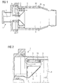
- FIG 5
- einen Querschnitt durch einen als Resonator ausgebildeten Hohlraum mit Pilotbrenner,
- FIG 6
- einen Querschnitt durch ein can/can-annular Brennersystem nach dem Stand der Technik,
- FIG 7
- einen Querschnitt durch einen Brenner mit erfindungsgemäßem als Resonator ausgebildetem Hohlraum,
- FIG 8
- einen Querschnitt durch einen Brenner mit erfindungsgemäßen als Resonator ausgebildetem Hohlraum und axialer Unterteilung,
- FIG 9
- einen Querschnitt durch einen Brenner mit erfindungsgemäßen als Resonator ausgebildetem Hohlraum und Grenzschichtabsaugungsposition,
- FIG 10
- einen Querschnitt durch einen Brenner mit erfindungsgemäßen als Resonator ausgebildeten Hohlraum und alternativer Grenzschichtabsaugungsposition,
- FIG 11
- einen Querschnitt durch einen Brenner mit erfindungsgemäßen als Resonator ausgebildetem Hohlraum und Einsatz,
- FIG 12
- einen Querschnitt durch Brenner mit erfindungsgemä-ßen als Resonator ausgebildetem Hohlraum und Hauptdrallerzeugerverlängerung.
- FIG. 1
- Cross section through a burner with a cavity designed as a resonator according to the invention,
- FIG. 2
- a cross section through a cavity according to the invention designed as a resonator,
- FIG. 3a, b
- a cross section through a resonator cavity according to the invention with different resonator inserts,
- FIG. 4
- a cross-section through a resonator cavity according to the invention with cooling air insert,
- FIG. 5
- a cross section through a trained as a resonator cavity with pilot burner,
- FIG. 6
- a cross section through a can / can-annular burner system according to the prior art,
- FIG. 7
- a cross section through a burner with inventive designed as a resonator cavity,
- FIG. 8
- a cross section through a burner with resonator designed according to the invention cavity and axial division,
- FIG. 9
- 3 shows a cross section through a burner with a cavity designed according to the invention as a resonator and boundary layer suction position, FIG.
- FIG. 10
- 3 shows a cross section through a burner with a resonator cavity according to the invention and an alternative boundary layer suction position,
- FIG. 11
- a cross section through a burner with resonator designed according to the invention cavity and insert,
- FIG. 12
- a cross section of burner with inventive Shen formed as a resonator cavity and Hauptdrallerzeugerverlängerung.
Gleiche Bezugszeichen haben in den verschiedenen Figuren die gleiche Bedeutung.Like reference numerals have the same meaning in the various figures.
In den als Resonator ausgebildeten Hohlraum 5 (
Auch die Anwendung in anderen Brennersystemen beispielsweise in einem Can- oder Can-Annualar System ist möglich.
Der Brenner 100 umfasst ein head-end, ein Überleitkanal 114, und dazwischen einen Liner 116. Dabei wird als "head-end" im Wesentlichen der Teilabschnitt der Kraftstoffeinspritzung 115/Kraftstoff-Luft Vormischung 117 des Brenners bezeichnet.The application in other burner systems, for example in a Can or Can Annualar system is possible.
The
Der Liner 116 erstreckt sich vom Head-End zu dem Überleitkanal 114 auf beliebige Weise. Während des Betriebs ist aufgrund der hier vorherrschenden Betriebstemperaturen, welche eine Beschädigung des Liners 116 hervorrufen können, eine Kühlung der Brennkammer sowie des Liners 116 notwendig. Hierzu wird in der Ringpassage 200, welche aus einer Umhüllung 118 und dem Liner 116 gebildet wird, Verbrennungs-/Kühlluft 220 eingeströmt. Diese Verbrennungs-/Kühlluft 220 wird anschließend der Brennkammer 112 zugeführt.The
Im als Resonator ausgeführten Hohlraum 40 kann der Hohlraum 40 selber mehrmals unterteilt sein, um verschiedene Frequenzen zu dämpfen(
Die Spülluft 113, welche den als Resonator ausgebildeten Hohlraum 40 durchströmt, kann gleichzeitig eine Kühlung, bevorzugt eine Prallkühlung 130, des head-ends und /oder der Brennkammer 112 bewirken (
The scavenging
Der Hohlraum 40 kann ebenfalls einen geschweißten Resonatoreinsatz oder einen verstellbaren Resonatoreinsatz aufweisen.
Der Hohlraum (5,40) kann auch nur Bohrungen an der der Brenkammer abgewandeten (=kalten Seite) aufweisen, welche Schwingungen im sogenannten Plenum oder im Ringkanal dämpfenThe cavity (5,40) may also only holes on the side facing away from the Brenkammer (= cold side), which dampen vibrations in the so-called plenum or in the annular channel
Das hier vorgestellte erfindungsgemäße Konzept, nämlich bereits vorhandene Hohlräume als Resonatoren zu nutzen, ist dabei nicht auf die hier vorgestellten Brenner/Brennertypen eingeschränkt. So ist auch auf Synthesegasbrenner, Silobrenner und auch andere Brenner dieses erfindungsgemäße Konzept anwendbar.The inventive concept presented here, namely to use already existing cavities as resonators, is not limited to the burner / burner types presented here. Thus, this concept according to the invention can also be applied to synthesis gas burners, silo burners and also other burners.
Claims (12)
dadurch gekennzeichnet, dass mindestens ein an oder/und im Brenner angebrachter Hohlraum (5,40) vorhanden ist, welcher mit dem Brenner (1,100) und/oder der Brennkammer (4,112) derart verbunden ist, so dass sich in dem mindestens einen Hohlraum (5,40) Schwingungen ausbilden, welche zur Dämpfung der thermoakustischen Brennkammerschwingung verwendbar sind und wobei der mindestens eine vorhandene Hohlraum (5,40) mit Spülluft (13,113) kühlbar ist.Device for damping combustion oscillations in a combustion chamber,
characterized in that at least one attached to and / or in the burner cavity (5,40) is present, which with the burner (1,100) and / or the combustion chamber (4,112) is connected such that in the at least one cavity ( 5.40) form vibrations which are usable for damping the thermoacoustic combustion chamber oscillation and wherein the at least one existing cavity (5, 40) with purge air (13, 113) is coolable.
dadurch gekennzeichnet, dass der mindestens eine vorhandene Hohlraum (5,40) durch mindestens ein Loch mit der Brennkammer (4,112) verbunden ist.Device according to claim 1,
characterized in that the at least one existing cavity (5,40) is connected by at least one hole with the combustion chamber (4,112).
dadurch gekennzeichnet, dass das mindestens eine Loch eine Bohrung ist.Device according to claim 2,
characterized in that the at least one hole is a bore.
dadurch gekennzeichnet, dass der mindestens eine vorhandene Hohlraum (5,40) durch Prallkühlung und/oder Konvektivkühlung kühlbar ist.Device according to one of claims 1-3,
characterized in that the at least one existing cavity (5,40) is cooled by impingement cooling and / or convective cooling.
dadurch gekennzeichnet, dass der mindestens eine Hohlraum (5,40) unterteilbar ist, so dass verschiedene Schwingungsfrequenzen gedämpft werden.Device according to one of claims 1-4,
characterized in that the at least one cavity (5,40) is divisible, so that different vibration frequencies are attenuated.
dadurch gekennzeichnet, dass der mindestens eine Hohlraum (5,40) an der der Brennkammer (4,112) zugewandten Umfangsseite des Brenners (1,100) angeordnet ist.Device according to one of claims 1-5,
characterized in that the at least one cavity (5,40) on the combustion chamber (4,112) facing the peripheral side of the burner (1,100) is arranged.
dadurch gekennzeichnet, dass mindestens zwei Hohlräume (5,40) vorgesehen sind, die ein gleich großes Volumen aufweisen.Device according to one of claims 1-6,
characterized in that at least two cavities (5,40) are provided which have an equal volume.
dadurch gekennzeichnet, dass der mindestens eine Hohlraum (5,40) als Helmholzresonator oder Lamda/4 Resonator (11) ausgestaltet ist.Device according to one of the preceding claims,
characterized in that the at least one cavity (5, 40) is designed as a Helmholtz resonator or Lamda / 4 resonator (11).
dadurch gekennzeichnet, dass mindestens ein an oder/und im Brenner(1,100) angebrachter Hohlraum (5,40) vorhanden ist, welcher mit dem Brenner (1,100) und/oder Brennkammer (4,112) derart verbunden ist, dass sich in dem mindestens einen Hohlraum (5,40) Schwingungen ausbilden, welche zur Dämpfung der Brennkammerschwingungen verwendet werden und wobei der mindestens eine vorhandene Hohlraum (1,100) mit Spülluft (13,113) gekühlt wird.Method for damping combustion oscillations in a combustion chamber (4,112),
characterized in that at least one attached to and / or in the burner (1,100) cavity (5,40) is present, which is connected to the burner (1,100) and / or combustion chamber (4,112) such that in the at least one cavity (5,40) form vibrations, which are used for damping the combustion chamber vibrations and wherein the at least one existing cavity (1,100) is cooled with purging air (13,113).
dadurch gekennzeichnet, dass die Spülluft (13,113) in der Brennkammer (4,112) nahezu vollständig an der Verbrennung teilnimmt.Method according to claim 10,
characterized in that the purging air (13,113) in the combustion chamber (4,112) almost completely participates in the combustion.
dadurch gekennzeichnet, dass der Hohlraum (4,50) in seiner akustischen Funktionsweise als Helmholzresonator oder Lambda/4 Resonator wirkt.Method according to one of claims 10-11,
characterized in that the cavity (4,50) acts in its acoustic operation as Helmholzresonator or lambda / 4 resonator.
Priority Applications (1)
| Application Number | Priority Date | Filing Date | Title |
|---|---|---|---|
| EP08016788A EP2187125A1 (en) | 2008-09-24 | 2008-09-24 | Method and device for damping combustion oscillation |
Applications Claiming Priority (1)
| Application Number | Priority Date | Filing Date | Title |
|---|---|---|---|
| EP08016788A EP2187125A1 (en) | 2008-09-24 | 2008-09-24 | Method and device for damping combustion oscillation |
Publications (1)
| Publication Number | Publication Date |
|---|---|
| EP2187125A1 true EP2187125A1 (en) | 2010-05-19 |
Family
ID=40373520
Family Applications (1)
| Application Number | Title | Priority Date | Filing Date |
|---|---|---|---|
| EP08016788A Withdrawn EP2187125A1 (en) | 2008-09-24 | 2008-09-24 | Method and device for damping combustion oscillation |
Country Status (1)
| Country | Link |
|---|---|
| EP (1) | EP2187125A1 (en) |
Cited By (7)
| Publication number | Priority date | Publication date | Assignee | Title |
|---|---|---|---|---|
| EP2522910A1 (en) * | 2011-05-12 | 2012-11-14 | General Electric Company | Combustor Casing For Combustion Dynamics Mitigation |
| WO2013043078A1 (en) * | 2011-09-22 | 2013-03-28 | General Electric Company | Combustor cap for damping low frequency dynamics |
| ITMI20122265A1 (en) * | 2012-12-28 | 2014-06-29 | Ansaldo Energia Spa | BURNER GROUP FOR A GAS TURBINE PROVIDED WITH A HELMHOLTZ RESONATOR |
| WO2014139738A1 (en) * | 2013-03-13 | 2014-09-18 | Siemens Aktiengesellschaft | Jet burner with cooling duct in the base plate |
| WO2019067114A1 (en) * | 2017-09-28 | 2019-04-04 | Solar Turbines Incorporated | Scroll for fuel injector assemblies in gas turbine engines |
| CN111780159A (en) * | 2020-07-03 | 2020-10-16 | 中国科学院工程热物理研究所 | Clean cooling device of high-speed gas curtain of penetrating model combustion chamber adherence wall of optics |
| US20230407819A1 (en) * | 2022-06-17 | 2023-12-21 | Blue Origin, Llc | Multi-volume acoustic resonator for rocket engine |
Citations (17)
| Publication number | Priority date | Publication date | Assignee | Title |
|---|---|---|---|---|
| WO1993010401A1 (en) | 1991-11-15 | 1993-05-27 | Siemens Aktiengesellschaft | Arrangement for suppressing combustion-caused vibrations in the combustion chamber of a gas turbine system |
| EP0577862A1 (en) * | 1992-07-03 | 1994-01-12 | Abb Research Ltd. | Afterburner |
| EP0597138A1 (en) | 1992-11-09 | 1994-05-18 | Asea Brown Boveri Ag | Combustion chamber for gas turbine |
| DE19640980A1 (en) * | 1996-10-04 | 1998-04-16 | Asea Brown Boveri | Device for damping thermo-acoustic vibrations in combustion chamber of gas turbine |
| US6351947B1 (en) * | 2000-04-04 | 2002-03-05 | Abb Alstom Power (Schweiz) | Combustion chamber for a gas turbine |
| WO2002025174A1 (en) * | 2000-09-21 | 2002-03-28 | Siemens Westinghouse Power Corporation | Modular resonators for suppressing combustion instabilities in gas turbine power plants |
| EP1321713A2 (en) * | 2001-12-21 | 2003-06-25 | Nuovo Pignone Holding S.P.A. | An improved flame tube or liner for a combustion chamber of a gas turbine with low emission of pollutants |
| EP1342953A1 (en) * | 2002-03-07 | 2003-09-10 | Siemens Aktiengesellschaft | Gas turbine |
| EP1434006A2 (en) * | 2002-12-23 | 2004-06-30 | Rolls-Royce Plc | Combustion chamber for gas turbine engine |
| WO2005100858A1 (en) * | 2004-04-17 | 2005-10-27 | Astrium Gmbh | Damping of vibration of a combustion chamber by resonators |
| EP1605209A1 (en) * | 2004-06-07 | 2005-12-14 | Siemens Aktiengesellschaft | Combustor with thermo-acoustic vibrations dampening device |
| US20060059913A1 (en) * | 2004-09-21 | 2006-03-23 | Siemens Aktiengesellschaft | Combustion chamber for a gas turbine with at least two resonator devices |
| US20070169992A1 (en) * | 2006-01-25 | 2007-07-26 | Siemens Power Generation, Inc. | Acoustic resonator with impingement cooling tubes |
| EP1832812A2 (en) * | 2006-03-10 | 2007-09-12 | Rolls-Royce Deutschland Ltd & Co KG | Gas turbine combustion chamber wall with absorption of combustion chamber vibrations |
| DE102005062284A1 (en) * | 2005-12-24 | 2008-01-31 | Alstom Technology Ltd. | Combustion chamber for gas turbine of power plant system, has damping device that is formed as Helmholtz Resonator arrangement with helmholtz-Resonator including resonator area and resonator neck, and is attached to chamber through opening |
| US20080041058A1 (en) * | 2006-08-18 | 2008-02-21 | Siemens Power Generation, Inc. | Resonator device at junction of combustor and combustion chamber |
| DE102006040760A1 (en) * | 2006-08-31 | 2008-03-06 | Rolls-Royce Deutschland Ltd & Co Kg | Lean-burning gas turbine combustion chamber wall, has Inflow holes formed perpendicularly over chamber wall, and damping openings formed by shingle, where shingle is spaced apart from chamber wall by using side part |
-
2008
- 2008-09-24 EP EP08016788A patent/EP2187125A1/en not_active Withdrawn
Patent Citations (18)
| Publication number | Priority date | Publication date | Assignee | Title |
|---|---|---|---|---|
| WO1993010401A1 (en) | 1991-11-15 | 1993-05-27 | Siemens Aktiengesellschaft | Arrangement for suppressing combustion-caused vibrations in the combustion chamber of a gas turbine system |
| EP0577862A1 (en) * | 1992-07-03 | 1994-01-12 | Abb Research Ltd. | Afterburner |
| EP0597138A1 (en) | 1992-11-09 | 1994-05-18 | Asea Brown Boveri Ag | Combustion chamber for gas turbine |
| DE19640980A1 (en) * | 1996-10-04 | 1998-04-16 | Asea Brown Boveri | Device for damping thermo-acoustic vibrations in combustion chamber of gas turbine |
| US6351947B1 (en) * | 2000-04-04 | 2002-03-05 | Abb Alstom Power (Schweiz) | Combustion chamber for a gas turbine |
| WO2002025174A1 (en) * | 2000-09-21 | 2002-03-28 | Siemens Westinghouse Power Corporation | Modular resonators for suppressing combustion instabilities in gas turbine power plants |
| EP1321713A2 (en) * | 2001-12-21 | 2003-06-25 | Nuovo Pignone Holding S.P.A. | An improved flame tube or liner for a combustion chamber of a gas turbine with low emission of pollutants |
| WO2003074936A1 (en) | 2002-03-07 | 2003-09-12 | Siemens Aktiengesellschaft | Gas turbine |
| EP1342953A1 (en) * | 2002-03-07 | 2003-09-10 | Siemens Aktiengesellschaft | Gas turbine |
| EP1434006A2 (en) * | 2002-12-23 | 2004-06-30 | Rolls-Royce Plc | Combustion chamber for gas turbine engine |
| WO2005100858A1 (en) * | 2004-04-17 | 2005-10-27 | Astrium Gmbh | Damping of vibration of a combustion chamber by resonators |
| EP1605209A1 (en) * | 2004-06-07 | 2005-12-14 | Siemens Aktiengesellschaft | Combustor with thermo-acoustic vibrations dampening device |
| US20060059913A1 (en) * | 2004-09-21 | 2006-03-23 | Siemens Aktiengesellschaft | Combustion chamber for a gas turbine with at least two resonator devices |
| DE102005062284A1 (en) * | 2005-12-24 | 2008-01-31 | Alstom Technology Ltd. | Combustion chamber for gas turbine of power plant system, has damping device that is formed as Helmholtz Resonator arrangement with helmholtz-Resonator including resonator area and resonator neck, and is attached to chamber through opening |
| US20070169992A1 (en) * | 2006-01-25 | 2007-07-26 | Siemens Power Generation, Inc. | Acoustic resonator with impingement cooling tubes |
| EP1832812A2 (en) * | 2006-03-10 | 2007-09-12 | Rolls-Royce Deutschland Ltd & Co KG | Gas turbine combustion chamber wall with absorption of combustion chamber vibrations |
| US20080041058A1 (en) * | 2006-08-18 | 2008-02-21 | Siemens Power Generation, Inc. | Resonator device at junction of combustor and combustion chamber |
| DE102006040760A1 (en) * | 2006-08-31 | 2008-03-06 | Rolls-Royce Deutschland Ltd & Co Kg | Lean-burning gas turbine combustion chamber wall, has Inflow holes formed perpendicularly over chamber wall, and damping openings formed by shingle, where shingle is spaced apart from chamber wall by using side part |
Cited By (14)
| Publication number | Priority date | Publication date | Assignee | Title |
|---|---|---|---|---|
| EP2522910A1 (en) * | 2011-05-12 | 2012-11-14 | General Electric Company | Combustor Casing For Combustion Dynamics Mitigation |
| US9447970B2 (en) | 2011-05-12 | 2016-09-20 | General Electric Company | Combustor casing for combustion dynamics mitigation |
| WO2013043078A1 (en) * | 2011-09-22 | 2013-03-28 | General Electric Company | Combustor cap for damping low frequency dynamics |
| WO2014102749A1 (en) * | 2012-12-28 | 2014-07-03 | Ansaldo Energia S.P.A. | Gas turbine burner assembly equipped with a helmholtz resonator |
| ITMI20122265A1 (en) * | 2012-12-28 | 2014-06-29 | Ansaldo Energia Spa | BURNER GROUP FOR A GAS TURBINE PROVIDED WITH A HELMHOLTZ RESONATOR |
| CN105121961B (en) * | 2012-12-28 | 2017-05-31 | 安萨尔多能源公司 | Equipped with the gas turbine combustor component of Helmholtz resonator |
| WO2014139738A1 (en) * | 2013-03-13 | 2014-09-18 | Siemens Aktiengesellschaft | Jet burner with cooling duct in the base plate |
| CN105102893A (en) * | 2013-03-13 | 2015-11-25 | 西门子公司 | Jet burner with cooling duct in the base plate |
| CN105102893B (en) * | 2013-03-13 | 2017-06-06 | 西门子公司 | There is the atomizer burner of cooling duct in a substrate |
| US10088163B2 (en) | 2013-03-13 | 2018-10-02 | Siemens Aktiengesellschaft | Jet burner with cooling duct in the base plate |
| WO2019067114A1 (en) * | 2017-09-28 | 2019-04-04 | Solar Turbines Incorporated | Scroll for fuel injector assemblies in gas turbine engines |
| CN111780159A (en) * | 2020-07-03 | 2020-10-16 | 中国科学院工程热物理研究所 | Clean cooling device of high-speed gas curtain of penetrating model combustion chamber adherence wall of optics |
| US20230407819A1 (en) * | 2022-06-17 | 2023-12-21 | Blue Origin, Llc | Multi-volume acoustic resonator for rocket engine |
| US11867139B1 (en) * | 2022-06-17 | 2024-01-09 | Blue Origin, Llc | Multi-volume acoustic resonator for rocket engine |
Similar Documents
| Publication | Publication Date | Title |
|---|---|---|
| EP2340397B1 (en) | Burner insert for a gas turbine combustion chamber and gas turbine | |
| DE60105531T2 (en) | Gas turbine combustor, gas turbine and jet engine | |
| EP1481195B1 (en) | Burner, method for operating a burner and gas turbine | |
| EP1483536B1 (en) | Gas turbine | |
| EP2187125A1 (en) | Method and device for damping combustion oscillation | |
| DE102013108985A1 (en) | System for reducing combustion dynamics in gas turbine utilized for e.g. industrial operations, has fuel injection device extending through pipes, where fourth axial spacing in burner is different from fourth axial spacing in another burner | |
| WO2010066516A2 (en) | Fuel lance for a burner | |
| WO2014131876A1 (en) | Damping device for a gas turbine, gas turbine and method for damping thermo-acoustic vibrations | |
| DE102015122927A1 (en) | Pilot nozzle in a gas turbine combustor | |
| DE102014102584A1 (en) | Fuel nozzle to reduce the modal coupling of the combustion dynamics | |
| DE102008016931A1 (en) | System for reducing combustion chamber dynamics | |
| CH701461B1 (en) | Fuel nozzle assembly for a gas turbine engine. | |
| EP0971172B1 (en) | Gas turbine combustion chamber with silencing wall structure | |
| EP1605209B1 (en) | Combustor with thermo-acoustic vibrations dampening device | |
| DE102013114903A1 (en) | Combustion arrangement and method for reducing pressure fluctuations of a combustion arrangement | |
| EP2601447A2 (en) | Gas turbine combustion chamber | |
| EP2383515B1 (en) | Combustion system for dampening such a combustion system | |
| EP2409086B1 (en) | Burner assembly for a gas turbine | |
| EP2295858A1 (en) | Stabilising of the flame of a burner | |
| EP1775515A2 (en) | Resonating device for combustion chamber, combustion chamber and method for adjusting the acoustic characteristics of a combustion chamber | |
| EP2270397A1 (en) | Gas turbine combustor and gas turbine | |
| EP3088802A1 (en) | Nozzle for a gas turbine combustor | |
| DE102004009226A1 (en) | Burn control for gas turbine engine has a lean mixture input burn chamber linked to the main burn chamber via a double walled porous element | |
| DE102005059184B3 (en) | Apparatus and method for damping thermoacoustic resonances in combustion chambers | |
| EP2261563A1 (en) | Burner, operating method and fitting method |
Legal Events
| Date | Code | Title | Description |
|---|---|---|---|
| PUAI | Public reference made under article 153(3) epc to a published international application that has entered the european phase |
Free format text: ORIGINAL CODE: 0009012 |
|
| AK | Designated contracting states |
Kind code of ref document: A1 Designated state(s): AT BE BG CH CY CZ DE DK EE ES FI FR GB GR HR HU IE IS IT LI LT LU LV MC MT NL NO PL PT RO SE SI SK TR |
|
| AX | Request for extension of the european patent |
Extension state: AL BA MK RS |
|
| AKY | No designation fees paid | ||
| STAA | Information on the status of an ep patent application or granted ep patent |
Free format text: STATUS: THE APPLICATION IS DEEMED TO BE WITHDRAWN |
|
| 18D | Application deemed to be withdrawn |
Effective date: 20101120 |