EP0892216B1 - Structure de paroi de chambre de combustion absorbant les vibrations - Google Patents
Structure de paroi de chambre de combustion absorbant les vibrations Download PDFInfo
- Publication number
- EP0892216B1 EP0892216B1 EP97810489A EP97810489A EP0892216B1 EP 0892216 B1 EP0892216 B1 EP 0892216B1 EP 97810489 A EP97810489 A EP 97810489A EP 97810489 A EP97810489 A EP 97810489A EP 0892216 B1 EP0892216 B1 EP 0892216B1
- Authority
- EP
- European Patent Office
- Prior art keywords
- combustion chamber
- damping
- cells
- helmholtz
- turbine
- Prior art date
- Legal status (The legal status is an assumption and is not a legal conclusion. Google has not performed a legal analysis and makes no representation as to the accuracy of the status listed.)
- Expired - Lifetime
Links
Images

Classifications
-
- G—PHYSICS
- G10—MUSICAL INSTRUMENTS; ACOUSTICS
- G10K—SOUND-PRODUCING DEVICES; METHODS OR DEVICES FOR PROTECTING AGAINST, OR FOR DAMPING, NOISE OR OTHER ACOUSTIC WAVES IN GENERAL; ACOUSTICS NOT OTHERWISE PROVIDED FOR
- G10K11/00—Methods or devices for transmitting, conducting or directing sound in general; Methods or devices for protecting against, or for damping, noise or other acoustic waves in general
- G10K11/16—Methods or devices for protecting against, or for damping, noise or other acoustic waves in general
- G10K11/172—Methods or devices for protecting against, or for damping, noise or other acoustic waves in general using resonance effects
-
- F—MECHANICAL ENGINEERING; LIGHTING; HEATING; WEAPONS; BLASTING
- F23—COMBUSTION APPARATUS; COMBUSTION PROCESSES
- F23R—GENERATING COMBUSTION PRODUCTS OF HIGH PRESSURE OR HIGH VELOCITY, e.g. GAS-TURBINE COMBUSTION CHAMBERS
- F23R3/00—Continuous combustion chambers using liquid or gaseous fuel
- F23R3/002—Wall structures
-
- F—MECHANICAL ENGINEERING; LIGHTING; HEATING; WEAPONS; BLASTING
- F05—INDEXING SCHEMES RELATING TO ENGINES OR PUMPS IN VARIOUS SUBCLASSES OF CLASSES F01-F04
- F05B—INDEXING SCHEME RELATING TO WIND, SPRING, WEIGHT, INERTIA OR LIKE MOTORS, TO MACHINES OR ENGINES FOR LIQUIDS COVERED BY SUBCLASSES F03B, F03D AND F03G
- F05B2260/00—Function
- F05B2260/96—Preventing, counteracting or reducing vibration or noise
-
- F—MECHANICAL ENGINEERING; LIGHTING; HEATING; WEAPONS; BLASTING
- F23—COMBUSTION APPARATUS; COMBUSTION PROCESSES
- F23R—GENERATING COMBUSTION PRODUCTS OF HIGH PRESSURE OR HIGH VELOCITY, e.g. GAS-TURBINE COMBUSTION CHAMBERS
- F23R2900/00—Special features of, or arrangements for continuous combustion chambers; Combustion processes therefor
- F23R2900/00014—Reducing thermo-acoustic vibrations by passive means, e.g. by Helmholtz resonators
Definitions
- the invention relates to a gas turbine combustion chamber, the Combustion chamber wall at least partially cooled by effusion or film and extends from the combustion chamber inlet to the turbine, and attached to a front panel burner are arranged in the area of the combustion chamber Helmholtz damper are.
- thermoacoustic vibrations often occur in combustion chambers of gas turbines. Thereby, thermoacoustic vibrations are used to denote mutually rocking thermal and acoustic disturbances. High vibration amplitudes can occur, which can lead to undesired effects, such as a high mechanical load on the combustion chamber, increased NO x emissions due to inhomogeneous combustion and even an extinguishing of the flame.
- the cooling air flowing into the combustion chamber has an important function in conventional combustion chambers, since the cooling air film on the combustion chamber wall has a sound-absorbing effect and thus contributes to damping thermoacoustic vibrations.
- an increasing proportion of the air is passed through the burners themselves in modern gas turbines, so the cooling air flow is reduced.
- the problems mentioned at the outset which are associated with the undesirable vibrations, occur increasingly in such modern combustion chambers.
- the invention is therefore based on the object of a device for suppressing thermoacoustic combustion chamber vibrations to provide the smallest possible space gets along and also work in tight geometries leaves.
- Honeycomb mats have a structure that is made up of many neighboring but separate cells.
- the individual cells can have any shape, but the cells are preferably characterized by a base area and a vertical height thereon.
- the base can be triangular, rectangular, hexagonal, generally polygonal or irregular in shape. Rectangular and hexagonal cells are preferred.
- the structures are preferably only one cell thick, but several cells can also be stacked one above the other. However, the extension of the multicellular structure is always much smaller in the direction of the height of the cells than perpendicular to it, in the lateral plane of the base areas of the cells.
- the number of cells of the entire structure is in the present one Invention between 1,000 and about 200,000, preferred between 5000 and 50,000, particularly preferably between 10,000 and 30,000.
- a lesser or greater number of cells in A structure also makes sense since the number of cells primarily on the frequency spectrum to be attenuated and based on the required damping performance.
- each cell has at least one Opening, preferably two opposite one another Openings.
- each cell has at least one Opening, preferably two opposite one another Openings.
- the two openings on the top, for example and bottom of the mat so that the The cooling air flows through cells.
- the cell walls in which the openings are located have a not insignificant thickness.
- the openings are therefore hereinafter also referred to as pipes.
- the cells of the entire structure do not all have to be the same Shape, size, number of openings (tubes), length and diameter of pipes etc. Cells with different properties (About size) can serve various purposes, such as: dampen different frequencies.
- each cell forms a (at rinsed through two openings) Helmholtz resonator.
- the resonance frequency of such a Helmholtz resonator is due to the Area and length of the inlet openings and the volume of the Given cell. Flushed Helmholtz resonators offer that Advantage that they are cooled by the cooling air flowing through. Since the resonance frequency of a Helmholtz resonator from depends on the gas temperature, this resonance frequency kept stable.
- the cell volumes and the area and Length of the inlet openings chosen so that their resonance frequencies with certain frequencies of the combustion chamber to be damped to match.
- a Helmholtz resonator works in the area of its resonance frequency as a damper, because there the coupling the vibration to be damped to the resonator volume is particularly good.
- thermoacoustic oscillation occurs when the burner at a the natural frequencies of the combustion chamber with fluctuations in the React heat release.
- the frequency of the ensuing Experience has shown that vibration is close to one of the natural frequencies the combustion chamber. These are for typical combustion chambers generally between 40 Hz and 3 kHz. The lowest experience has shown that these natural frequencies are special Importance. However, it is often also the damping of higher eigenmodes important to the combustion chamber.
- a set of cells with their Properties (shape, volume, length and diameter of the pipes) matched to each of the frequencies to be attenuated.
- the individual cells are relatively small, the damping performance of a single cell is relatively low.
- this is offset by the large number of cells because in a first approximation the damping power is proportional to the number of the dampening cells.
- the combustion chamber walls are, for example, in an annular combustion chamber the outer shell, the inner shell and the front panel (i.e. the area where the burners are attached).
- the entire area of the Combustion chamber walls can be equipped with Helmholtz dampers.
- the required area results from the area to be reached Damping performance. For example, only one frequency the combustion chamber are damped, it may be enough, only that Equip the front panel with honeycomb mats and to leave the outer and inner shell unchanged.
- the exhaust housing is not shown the gas turbine with exhaust pipe and chimney, the compressor and the plenum of the turbine.
- the flow direction of the work equipment is marked with arrows.
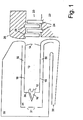
- Fig. 1 is a partial longitudinal section of an annular combustion chamber as an example shown. Although the following embodiment refer to such an annular combustion chamber the invention is not limited to ring combustion chambers, but generally applicable for effusion-cooled combustion chambers.
- the plant of which in Fig. 1 only that above the machine axis 30 lying part is shown, is rotationally symmetrical built up around the machine axis 30.
- the system On the side of the Gas turbine 20, the system consists essentially of the Blades 24 bladed rotor 22 and the guide vanes 28 equipped blade carrier 26.
- the blade carrier 26 is about corresponding recordings in the (not shown) turbine housing hooked.
- Compressed air 38 flows from the compressor into the collecting space 39.
- the majority of the air flows through the bypass openings 31 and in particular the cooling channels 30 and 32 in the Combustion chamber hood 34 and from there through the burner 16 in the Combustion chamber 10.
- a smaller part of the air flows as cooling air from the cooling channels 30 and 32 through a variety of Openings in the wall parts 18 in the combustion chamber 10 (effusion cooling).
- the reference numeral 14 marks the exit to Turbine 20.
- the wall parts 18 and the front panel 36 are now according to the invention at least in part by means of honeycomb mats as a multi-cell Helmholtz damper structure educated.
- FIG. 2 shows a section of a combustion chamber wall according to the invention in detail.
- the actual one Combustion chamber wall 40 with a multi-cell mat from Helmholtz dampers 42 provided.
- the cooling air flows through the entry openings (or entry pipe) 46 into the cell volume 48 and then flows through the outlet openings 44 in the combustion chamber 10. Since the outlet opening 44 has the vapor properties of the damping element, it will hereinafter also referred to as the damping tube 44.
- the total pressure is p about 30 bar.
- the pressure loss ⁇ p due to the effusion cooling should be around 2%, i.e. around 60,000 Pa.
- the entire mass flow the air in the combustion chamber is 135 kg / s, the Cooling air flow should be about 1% of it, here 1.5 kg / s.
- the temperature of the cooling air is about 720 K, the speed of sound c at this temperature about 550 m / s.
- the required area for the cooling air openings can be estimated.
- ⁇ p / RT
- R gas constant R
- the density of the cooling air ⁇ ⁇ 15 kg / m 3 is obtained .
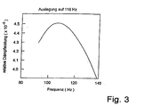
- a frequency of 116 Hz should be damped with the Helmholtz dampers.
- the entire pressure loss ⁇ p is to be produced at the inlet openings 46.
- the diameter of the inlet openings 46 is chosen to be 0.35 mm and the diameter of the damping tube 44 to be 0.8 mm.
- the length of the damping tube l d is also chosen to be 15 mm
- the height of a resonator cell 62 is 9 cm
- the base area of a resonator cell is 2.11 cm 2 .
- the volume V of a Helmholtz damper 42 is then 19 ml (1.9 x 10 -5 m 3 ), so that the required resonance and thus damping frequency is obtained.
- the damping tubes 44 are designed for a length of 15 mm.
- combustion chamber wall 40 of the exemplary embodiment has only one Thickness of 7.5 mm.
- 20,000 damper cells were used. This reduces the output pressure fluctuation from 100 mbar to a damped pressure fluctuation of around 30 mbar.
- the inlet openings 46 In the first design example, almost the entire pressure loss was provided through the inlet openings 46. If this is not desired the inlet openings 46 can be made larger. In the second design example, the diameter is accordingly of the inlet openings 46 to 0.7 mm and the diameter of the Damping tube 44 selected to 0.8 mm. Because of the larger inlet diameter the damping in this example is somewhat lower. With the same choice of the remaining parameters as in example 1, in this example there will be an output pressure fluctuation for 20,000 dampers from 100 mbar to a damped pressure fluctuation reduced by around 40 mbar.
Claims (3)
- Chambre de combustion à vibrations thermoacoustiques réduites pour turbine à gaz, dont la paroi (18) de chambre de combustion s'étend depuis l'entrée (12) de la chambre de combustion jusqu'à la turbine (20), et dans laquelle des brûleurs (16) sont fixés à un panneau frontal (36), des amortisseurs de Helmholtz (42) étant disposés dans la région de la chambre de combustion (10) au moins dans des parties de la paroi (18) de la chambre de combustion et/ou du panneau frontal (36), ces amortisseurs étant des éléments d'une structure multicellulaire, au moins une partie des amortisseurs de Helmholtz (42) étant traversée par de l'air de refroidissement, caractérisée en ce que la structure multicellulaire comprend des treillis en forme de nid d'abeilles.
- Chambre de combustion de turbine à gaz selon la revendication 1, caractérisée en ce que la structure multicellulaire comprend des treillis en forme de nid d'abeilles présentant différentes propriétés.
- Chambre de turbine à gaz selon la revendication 1, caractérisée en ce que le nombre de cellules de la structure multicellulaire est compris entre 1 000 et environ 200 000, de préférence entre 5 000 et 50 000 et de façon particulièrement préférable entre 10 000 et 30 000.
Priority Applications (3)
| Application Number | Priority Date | Filing Date | Title |
|---|---|---|---|
| DE59709276T DE59709276D1 (de) | 1997-07-15 | 1997-07-15 | Schwingungsdämpfende Brennkammerwandstruktur |
| AT97810489T ATE232287T1 (de) | 1997-07-15 | 1997-07-15 | Schwingungsdämpfende brennkammerwandstruktur |
| EP97810489A EP0892216B1 (fr) | 1997-07-15 | 1997-07-15 | Structure de paroi de chambre de combustion absorbant les vibrations |
Applications Claiming Priority (1)
| Application Number | Priority Date | Filing Date | Title |
|---|---|---|---|
| EP97810489A EP0892216B1 (fr) | 1997-07-15 | 1997-07-15 | Structure de paroi de chambre de combustion absorbant les vibrations |
Publications (2)
| Publication Number | Publication Date |
|---|---|
| EP0892216A1 EP0892216A1 (fr) | 1999-01-20 |
| EP0892216B1 true EP0892216B1 (fr) | 2003-02-05 |
Family
ID=8230302
Family Applications (1)
| Application Number | Title | Priority Date | Filing Date |
|---|---|---|---|
| EP97810489A Expired - Lifetime EP0892216B1 (fr) | 1997-07-15 | 1997-07-15 | Structure de paroi de chambre de combustion absorbant les vibrations |
Country Status (3)
| Country | Link |
|---|---|
| EP (1) | EP0892216B1 (fr) |
| AT (1) | ATE232287T1 (fr) |
| DE (1) | DE59709276D1 (fr) |
Cited By (1)
| Publication number | Priority date | Publication date | Assignee | Title |
|---|---|---|---|---|
| DE102006053278A1 (de) * | 2006-11-03 | 2008-05-08 | Deutsches Zentrum für Luft- und Raumfahrt e.V. | Brennkammervorrichtung |
Families Citing this family (12)
| Publication number | Priority date | Publication date | Assignee | Title |
|---|---|---|---|---|
| EP0990851B1 (fr) * | 1998-09-30 | 2003-07-23 | ALSTOM (Switzerland) Ltd | Chambre de combustion pour une turbine à gaz |
| US6351947B1 (en) | 2000-04-04 | 2002-03-05 | Abb Alstom Power (Schweiz) | Combustion chamber for a gas turbine |
| US6530221B1 (en) | 2000-09-21 | 2003-03-11 | Siemens Westinghouse Power Corporation | Modular resonators for suppressing combustion instabilities in gas turbine power plants |
| US6973790B2 (en) | 2000-12-06 | 2005-12-13 | Mitsubishi Heavy Industries, Ltd. | Gas turbine combustor, gas turbine, and jet engine |
| JP3676228B2 (ja) | 2000-12-06 | 2005-07-27 | 三菱重工業株式会社 | ガスタービン燃焼器およびガスタービン並びにジェットエンジン |
| JP2002195565A (ja) * | 2000-12-26 | 2002-07-10 | Mitsubishi Heavy Ind Ltd | ガスタービン燃焼器 |
| EP1221574B2 (fr) † | 2001-01-09 | 2017-12-20 | Mitsubishi Heavy Industries, Ltd. | Chambre de combustion de turbine à gaz |
| JP3962554B2 (ja) | 2001-04-19 | 2007-08-22 | 三菱重工業株式会社 | ガスタービン燃焼器及びガスタービン |
| EP1832812A3 (fr) * | 2006-03-10 | 2012-01-04 | Rolls-Royce Deutschland Ltd & Co KG | Paroi de chambre de combustion de turbine à gaz avec amortissement des vibrations de la chambre de combustion |
| ES2400267T3 (es) * | 2009-08-31 | 2013-04-08 | Alstom Technology Ltd | Dispositivo de combustión de una turbina de gas |
| FR2962586B1 (fr) * | 2010-07-09 | 2013-05-24 | Airbus Operations Sas | Panneau pour le traitement acoustique |
| EP2837782A1 (fr) | 2013-08-14 | 2015-02-18 | Alstom Technology Ltd | Dispositif d'amortissement d'oscillation de combustion dans une turbine à gaz |
Family Cites Families (4)
| Publication number | Priority date | Publication date | Assignee | Title |
|---|---|---|---|---|
| US4199936A (en) * | 1975-12-24 | 1980-04-29 | The Boeing Company | Gas turbine engine combustion noise suppressor |
| GB2038410B (en) * | 1978-12-27 | 1982-11-17 | Rolls Royce | Acoustic lining utilising resonance |
| DE59208715D1 (de) * | 1992-11-09 | 1997-08-21 | Asea Brown Boveri | Gasturbinen-Brennkammer |
| EP0702141B1 (fr) * | 1994-09-14 | 2002-05-08 | Mitsubishi Jukogyo Kabushiki Kaisha | Ensemble parois pour une tuyére de propulsion d'un moteur reacteur supersonique |
-
1997
- 1997-07-15 EP EP97810489A patent/EP0892216B1/fr not_active Expired - Lifetime
- 1997-07-15 AT AT97810489T patent/ATE232287T1/de not_active IP Right Cessation
- 1997-07-15 DE DE59709276T patent/DE59709276D1/de not_active Expired - Lifetime
Cited By (1)
| Publication number | Priority date | Publication date | Assignee | Title |
|---|---|---|---|---|
| DE102006053278A1 (de) * | 2006-11-03 | 2008-05-08 | Deutsches Zentrum für Luft- und Raumfahrt e.V. | Brennkammervorrichtung |
Also Published As
| Publication number | Publication date |
|---|---|
| ATE232287T1 (de) | 2003-02-15 |
| DE59709276D1 (de) | 2003-03-13 |
| EP0892216A1 (fr) | 1999-01-20 |
Similar Documents
| Publication | Publication Date | Title |
|---|---|---|
| EP0892216B1 (fr) | Structure de paroi de chambre de combustion absorbant les vibrations | |
| EP0597138B1 (fr) | Chambre de combustion pour turbine à gaz | |
| DE60215307T2 (de) | Auslassschalldämpfer für Gasturbinen | |
| DE19640980B4 (de) | Vorrichtung zur Dämpfung von thermoakustischen Schwingungen in einer Brennkammer | |
| DE4316475C2 (de) | Gasturbinen-Brennkammer | |
| DE102011018937A1 (de) | Verbrennungsvorrichtung für eine Gasturbine | |
| DE602005001682T2 (de) | Helmholtzresonator für eine Brennkammer eines Gasturbinentriebwerks | |
| EP2559942A1 (fr) | Tête de chambre de combustion d'une turbine à gaz dotée d'un refroidissement et d'un amortissement | |
| DE10325691A1 (de) | Wiederaufheizverbrennungssystem für eine Gasturbine | |
| EP1422403B1 (fr) | Dispositif de vaporisation d'eau pour turbines à gaz | |
| EP0892217B1 (fr) | Dispositif d'atténuation des vibrations d'une chambre de combustion | |
| EP1913242B1 (fr) | Silencieux pour installations de turbines a gaz | |
| DE2534556B2 (de) | Schalldämpfer für Gasströme | |
| EP1048898B1 (fr) | Brûleur | |
| EP2334558A2 (fr) | Silencieux pour un groupe auxiliaire d'un avion | |
| EP0971172B1 (fr) | Chambre de combustion pour turbine à gaz avec paroi à structure silencieuse | |
| EP2500648B1 (fr) | Chambre de combustion de turbines à gaz | |
| WO2013029981A1 (fr) | Chambre de combustion pour une installation de turbine à gaz | |
| EP3117148B1 (fr) | Système de combustion avec résonateur | |
| EP0990851B1 (fr) | Chambre de combustion pour une turbine à gaz | |
| DE102006040760A1 (de) | Gasturbinenbrennkammerwand für eine mager-brennende Gasturbinenbrennkammer | |
| DE102004010620B4 (de) | Brennkammer zur wirksamen Nutzung von Kühlluft zur akustischen Dämpfung von Brennkammerpulsation | |
| DE19939235B4 (de) | Verfahren zum Erzeugen von heissen Gasen in einer Verbrennungseinrichtung sowie Verbrennungseinrichtung zur Durchführung des Verfahrens | |
| WO2010149420A1 (fr) | Agencement de chambre de combustion pour l'amortissement de vibrations thermo-acoustiques, turbine à gaz et procédé pour utiliser une telle turbine à gaz | |
| DE102017126980A1 (de) | System und Verfahren zur Fluidakustikbehandlung |
Legal Events
| Date | Code | Title | Description |
|---|---|---|---|
| PUAI | Public reference made under article 153(3) epc to a published international application that has entered the european phase |
Free format text: ORIGINAL CODE: 0009012 |
|
| AK | Designated contracting states |
Kind code of ref document: A1 Designated state(s): AT BE CH DE FR GB LI |
|
| AX | Request for extension of the european patent |
Free format text: AL;LT;LV;RO;SI |
|
| 17P | Request for examination filed |
Effective date: 19990619 |
|
| AKX | Designation fees paid |
Free format text: AT BE CH DE FR GB LI |
|
| RAP1 | Party data changed (applicant data changed or rights of an application transferred) |
Owner name: ALSTOM |
|
| 17Q | First examination report despatched |
Effective date: 20011210 |
|
| GRAG | Despatch of communication of intention to grant |
Free format text: ORIGINAL CODE: EPIDOS AGRA |
|
| GRAG | Despatch of communication of intention to grant |
Free format text: ORIGINAL CODE: EPIDOS AGRA |
|
| GRAH | Despatch of communication of intention to grant a patent |
Free format text: ORIGINAL CODE: EPIDOS IGRA |
|
| GRAH | Despatch of communication of intention to grant a patent |
Free format text: ORIGINAL CODE: EPIDOS IGRA |
|
| RAP1 | Party data changed (applicant data changed or rights of an application transferred) |
Owner name: ALSTOM (SWITZERLAND) LTD |
|
| GRAA | (expected) grant |
Free format text: ORIGINAL CODE: 0009210 |
|
| AK | Designated contracting states |
Designated state(s): AT BE CH DE FR GB LI |
|
| PG25 | Lapsed in a contracting state [announced via postgrant information from national office to epo] |
Ref country code: FR Free format text: LAPSE BECAUSE OF FAILURE TO SUBMIT A TRANSLATION OF THE DESCRIPTION OR TO PAY THE FEE WITHIN THE PRESCRIBED TIME-LIMIT Effective date: 20030205 |
|
| REG | Reference to a national code |
Ref country code: GB Ref legal event code: FG4D Free format text: NOT ENGLISH |
|
| REG | Reference to a national code |
Ref country code: CH Ref legal event code: EP |
|
| REF | Corresponds to: |
Ref document number: 59709276 Country of ref document: DE Date of ref document: 20030313 Kind code of ref document: P |
|
| GBT | Gb: translation of ep patent filed (gb section 77(6)(a)/1977) |
Effective date: 20030506 |
|
| PG25 | Lapsed in a contracting state [announced via postgrant information from national office to epo] |
Ref country code: AT Free format text: LAPSE BECAUSE OF NON-PAYMENT OF DUE FEES Effective date: 20030715 |
|
| PGFP | Annual fee paid to national office [announced via postgrant information from national office to epo] |
Ref country code: BE Payment date: 20030724 Year of fee payment: 7 |
|
| PG25 | Lapsed in a contracting state [announced via postgrant information from national office to epo] |
Ref country code: LI Free format text: LAPSE BECAUSE OF NON-PAYMENT OF DUE FEES Effective date: 20030731 Ref country code: CH Free format text: LAPSE BECAUSE OF NON-PAYMENT OF DUE FEES Effective date: 20030731 |
|
| PLBE | No opposition filed within time limit |
Free format text: ORIGINAL CODE: 0009261 |
|
| STAA | Information on the status of an ep patent application or granted ep patent |
Free format text: STATUS: NO OPPOSITION FILED WITHIN TIME LIMIT |
|
| EN | Fr: translation not filed | ||
| 26N | No opposition filed |
Effective date: 20031106 |
|
| REG | Reference to a national code |
Ref country code: CH Ref legal event code: PL |
|
| PG25 | Lapsed in a contracting state [announced via postgrant information from national office to epo] |
Ref country code: BE Free format text: LAPSE BECAUSE OF NON-PAYMENT OF DUE FEES Effective date: 20040731 |
|
| BERE | Be: lapsed |
Owner name: *ALSTOM (SWITZERLAND) LTD Effective date: 20040731 |
|
| BERE | Be: lapsed |
Owner name: *ALSTOM (SWITZERLAND) LTD Effective date: 20040731 |
|
| PGFP | Annual fee paid to national office [announced via postgrant information from national office to epo] |
Ref country code: GB Payment date: 20110622 Year of fee payment: 15 |
|
| PGFP | Annual fee paid to national office [announced via postgrant information from national office to epo] |
Ref country code: DE Payment date: 20110729 Year of fee payment: 15 |
|
| GBPC | Gb: european patent ceased through non-payment of renewal fee |
Effective date: 20120715 |
|
| PG25 | Lapsed in a contracting state [announced via postgrant information from national office to epo] |
Ref country code: GB Free format text: LAPSE BECAUSE OF NON-PAYMENT OF DUE FEES Effective date: 20120715 Ref country code: DE Free format text: LAPSE BECAUSE OF NON-PAYMENT OF DUE FEES Effective date: 20130201 |
|
| REG | Reference to a national code |
Ref country code: DE Ref legal event code: R119 Ref document number: 59709276 Country of ref document: DE Effective date: 20130201 |