EP1422402A1 - Verfahren zum schliessen einer arbeitsbohrung in der oberseite einer gasturbinenschaufel - Google Patents
Verfahren zum schliessen einer arbeitsbohrung in der oberseite einer gasturbinenschaufel Download PDFInfo
- Publication number
- EP1422402A1 EP1422402A1 EP02770174A EP02770174A EP1422402A1 EP 1422402 A1 EP1422402 A1 EP 1422402A1 EP 02770174 A EP02770174 A EP 02770174A EP 02770174 A EP02770174 A EP 02770174A EP 1422402 A1 EP1422402 A1 EP 1422402A1
- Authority
- EP
- European Patent Office
- Prior art keywords
- tip
- welding
- section
- hole
- turbine blade
- Prior art date
- Legal status (The legal status is an assumption and is not a legal conclusion. Google has not performed a legal analysis and makes no representation as to the accuracy of the status listed.)
- Withdrawn
Links
Images


Classifications
-
- B—PERFORMING OPERATIONS; TRANSPORTING
- B23—MACHINE TOOLS; METAL-WORKING NOT OTHERWISE PROVIDED FOR
- B23K—SOLDERING OR UNSOLDERING; WELDING; CLADDING OR PLATING BY SOLDERING OR WELDING; CUTTING BY APPLYING HEAT LOCALLY, e.g. FLAME CUTTING; WORKING BY LASER BEAM
- B23K26/00—Working by laser beam, e.g. welding, cutting or boring
- B23K26/20—Bonding
- B23K26/206—Laser sealing
-
- B—PERFORMING OPERATIONS; TRANSPORTING
- B23—MACHINE TOOLS; METAL-WORKING NOT OTHERWISE PROVIDED FOR
- B23K—SOLDERING OR UNSOLDERING; WELDING; CLADDING OR PLATING BY SOLDERING OR WELDING; CUTTING BY APPLYING HEAT LOCALLY, e.g. FLAME CUTTING; WORKING BY LASER BEAM
- B23K26/00—Working by laser beam, e.g. welding, cutting or boring
- B23K26/20—Bonding
- B23K26/21—Bonding by welding
- B23K26/24—Seam welding
- B23K26/28—Seam welding of curved planar seams
-
- F—MECHANICAL ENGINEERING; LIGHTING; HEATING; WEAPONS; BLASTING
- F01—MACHINES OR ENGINES IN GENERAL; ENGINE PLANTS IN GENERAL; STEAM ENGINES
- F01D—NON-POSITIVE DISPLACEMENT MACHINES OR ENGINES, e.g. STEAM TURBINES
- F01D5/00—Blades; Blade-carrying members; Heating, heat-insulating, cooling or antivibration means on the blades or the members
- F01D5/12—Blades
- F01D5/14—Form or construction
- F01D5/147—Construction, i.e. structural features, e.g. of weight-saving hollow blades
-
- F—MECHANICAL ENGINEERING; LIGHTING; HEATING; WEAPONS; BLASTING
- F01—MACHINES OR ENGINES IN GENERAL; ENGINE PLANTS IN GENERAL; STEAM ENGINES
- F01D—NON-POSITIVE DISPLACEMENT MACHINES OR ENGINES, e.g. STEAM TURBINES
- F01D5/00—Blades; Blade-carrying members; Heating, heat-insulating, cooling or antivibration means on the blades or the members
- F01D5/12—Blades
- F01D5/14—Form or construction
- F01D5/18—Hollow blades, i.e. blades with cooling or heating channels or cavities; Heating, heat-insulating or cooling means on blades
-
- F—MECHANICAL ENGINEERING; LIGHTING; HEATING; WEAPONS; BLASTING
- F01—MACHINES OR ENGINES IN GENERAL; ENGINE PLANTS IN GENERAL; STEAM ENGINES
- F01D—NON-POSITIVE DISPLACEMENT MACHINES OR ENGINES, e.g. STEAM TURBINES
- F01D5/00—Blades; Blade-carrying members; Heating, heat-insulating, cooling or antivibration means on the blades or the members
- F01D5/12—Blades
- F01D5/14—Form or construction
- F01D5/20—Specially-shaped blade tips to seal space between tips and stator
-
- F—MECHANICAL ENGINEERING; LIGHTING; HEATING; WEAPONS; BLASTING
- F02—COMBUSTION ENGINES; HOT-GAS OR COMBUSTION-PRODUCT ENGINE PLANTS
- F02C—GAS-TURBINE PLANTS; AIR INTAKES FOR JET-PROPULSION PLANTS; CONTROLLING FUEL SUPPLY IN AIR-BREATHING JET-PROPULSION PLANTS
- F02C3/00—Gas-turbine plants characterised by the use of combustion products as the working fluid
- F02C3/04—Gas-turbine plants characterised by the use of combustion products as the working fluid having a turbine driving a compressor
- F02C3/045—Gas-turbine plants characterised by the use of combustion products as the working fluid having a turbine driving a compressor having compressor and turbine passages in a single rotor-module
- F02C3/05—Gas-turbine plants characterised by the use of combustion products as the working fluid having a turbine driving a compressor having compressor and turbine passages in a single rotor-module the compressor and the turbine being of the radial flow type
-
- F—MECHANICAL ENGINEERING; LIGHTING; HEATING; WEAPONS; BLASTING
- F02—COMBUSTION ENGINES; HOT-GAS OR COMBUSTION-PRODUCT ENGINE PLANTS
- F02C—GAS-TURBINE PLANTS; AIR INTAKES FOR JET-PROPULSION PLANTS; CONTROLLING FUEL SUPPLY IN AIR-BREATHING JET-PROPULSION PLANTS
- F02C3/00—Gas-turbine plants characterised by the use of combustion products as the working fluid
- F02C3/20—Gas-turbine plants characterised by the use of combustion products as the working fluid using a special fuel, oxidant, or dilution fluid to generate the combustion products
- F02C3/30—Adding water, steam or other fluids for influencing combustion, e.g. to obtain cleaner exhaust gases
-
- F—MECHANICAL ENGINEERING; LIGHTING; HEATING; WEAPONS; BLASTING
- F05—INDEXING SCHEMES RELATING TO ENGINES OR PUMPS IN VARIOUS SUBCLASSES OF CLASSES F01-F04
- F05D—INDEXING SCHEME FOR ASPECTS RELATING TO NON-POSITIVE-DISPLACEMENT MACHINES OR ENGINES, GAS-TURBINES OR JET-PROPULSION PLANTS
- F05D2230/00—Manufacture
- F05D2230/20—Manufacture essentially without removing material
- F05D2230/23—Manufacture essentially without removing material by permanently joining parts together
Definitions
- the present invention relates to a method for plugging a hole on a tip of a gas turbine blade for detaching a core formed thereinside.
- the present invention relates to a method for plugging a hole on a tip of a gas turbine blade wherein it is possible to plug a hole reliably and the plugging operation is preferably efficient.
- a gas turbine blade is exposed to a high temperature operation gas. Therefore, an Nickel-base super alloy which contains quite a few amount of Al and Ti is commonly used for a member for forming a gas turbine blade so as to enhance an anti-creeping characteristics which is caused under a high temperature condition. Also, for dealing with a super high temperature condition, it becomes more common that a directionally solidified coagulant and single crystal member are used so as to regulate a directivity of crystal growth in the single crystal member.
- a cooling agent flows in a gas turbine blade (hereinafter called a turbine blade and a temperature which is loaded to the turbine blade is maintained in a lower temperature.
- coolant paths which expand in a longitudinal direction (in a vertical direction) in the turbine blade are formed such that a plurality of coolant paths are formed in a plurality of channels in a width direction of the turbine blade, the coolant agent returns at a section where the neighboring channels communicate each other at an end of the turbine blade; thus, a channel or a plurality of channels are formed in a winding manner.
- a plurality of coolant paths 53, 53, 53 which expand toward a blade tip section 52 in a longitudinal direction (vertical direction) are separated by separating walls 54a, 54b, and 54c inside a turbine blade main body 51.
- a coolant agent returns at an end of the blade where the neighboring channels 53, 53 communicate each other; thus, the coolant agent flows in a winding manner so as to make use of its cooling characteristics.
- the turbine blade main body 51 having such a structure is formed by a casting operation while forming a hole 55 for detaching a plurality of cores in a blade tip section 52.
- the hole 55 is plugged to a tip plug 56 having a corresponding shape to the hole 55 by a tungsten inert-gas arc welding (hereinafter called a TIG welding).
- a method in which a lid is attached on the blade tip on a significant part of the blade and a plug is welded to the blade tip section by using a laser beam is used.
- a method for a gas turbine blade in which a lid is welded to the blade tip section is used.
- An object of the present invention is to provide a method for plugging a hole on a gas turbine blade tip such that it is possible to produce a final product repeatedly in a uniform quality by improving an efficiency for plugging hole on a tip of a turbine blade main body by a tip plug in a laser welding method in which high temperature heating area is narrow and an energy density is high.
- a first aspect of the present invention may be a method for plugging a hole on a tip of a gas turbine blade which comprises steps of fitting a tip plug in a hole formed on a tip of the turbine blade, performing a butt-weld at a butting section by a tip plug and the tip of the turbine blade by using a laser beam: and plugging the hole.
- a second aspect of the present invention may be a method for plugging a hole on a tip of a gas turbine blade in which a space in a butting section between the hole and the tip plug is no more than 0.2 mm.
- a third aspect of the present invention may be a method for plugging a hole on a tip of a gas turbine blade in which the tip plug is made of a Ni-base super alloy Inconel . 625 member.
- a fourth aspect of the present invention may be a method for plugging a hole on a tip of a gas turbine blade in which a condition for butt-welding is such as output: 500 to 900W, pulse width 10 to 15 ms, repetition time: 30 to 60 pps, Duty 30 to 90%, velocity: 0.5 to 1.3 m/min, and entering heat 34 to 60 kJ/m.
- a condition for butt-welding is such as output: 500 to 900W, pulse width 10 to 15 ms, repetition time: 30 to 60 pps, Duty 30 to 90%, velocity: 0.5 to 1.3 m/min, and entering heat 34 to 60 kJ/m.
- a fifth aspect of the present invention may be a method for plugging a hole on a tip of a gas turbine blade in which a defocusing amount of the laser beam is 0 to -1.0 mm in a butt-welding operation for welding a tip plug on a hole by a laser beam.
- a sixth aspect of the present invention may be a method for plugging a hole on a tip of a gas turbine blade in which the laser beam is a YAG laser beam, and an Argon gas is used for a shield gas.
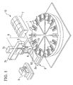
- Method for plugging a hole formed on a tip of the gas turbine blade is performed in such a way that a tip plug is welded on a hole on a tip of a turbine blade by a butt-welding operation by using a laser welding device for plugging a hole shown in FIG. 1.
- a rotation table 1 ⁇ is rotated at a predetermined constant angle intermittently by a driving device which is not shown in the drawing.
- a plurality of fixtures 2 are disposed on an upper surface of the rotation table 1 so as to correspond to the above predetermined constant intermittent angle.
- a blade main body is fixed on each fixture 2 such that a blade tip section 52 is disposed upwardly.
- Reference numeral 3 indicates a welding head driving device which is disposed near an outer periphery of the rotation table 1.
- the welding head driving device 3 is provided with an X-axis driving section 3X, a Y-axis driving section 3Y, and a Z-axis driving section 3Z so as to support the welding device which is mainly formed by a welding head 4 so as to freely move the welding device in a three-dimensional manner.
- the welding head which is supported by the welding head driving device 3 is provided with an optical system which focuses a laser beam which is sent from the optical fiber 8 and an ejection nozzle for an inert gas which protects the welding section from being oxidized.
- a tip of the welding head 4 is disposed so as to face the blade tip section 52 on the blade main body 51 so as to freely move therearound.
- a camera device 5 for monitoring a blade tip section 52 is disposed near the welding head 4 on the blade main body 51 in a perspective of the camera device 5 in a certain distance therefrom.
- Reference numeral 7 indicates a welding operation device which is provided with a laser oscillator for supplying a laser beam to the welding head 4.
- the welding operation device 7 supplies the laser beam to the welding head 4 via the optical fiber 8
- reference numeral 9 indicates a control device which is disposed so as to neighbor the welding head driving device 3.
- the control device 9 transmits a data which is taken by the camera device 5 via a transmission path (which is not shown in the drawing) and performs a position correction operation for the picked-up image by performing an image processing operation using a predetermined mark which is drawn on the tip plug 56 so as to control the movement of the welding head 4 by putting out the result to the welding head driving device 3.
- a laser welding device for plugging a hole having such structures seals a hole formed on the blade tip section 52 according to following manner.
- a tip plug is fit to a hole 55 which is formed on the blade tip section 52 on the blade main body 51. Simultaneously, the tip plug 56 is welded temporarily according to necessity.
- base sections of the blade main body 51 is fixed by a fixture 2 so as to be supported on the rotation table 1.
- an image of the tip plug 56 is picked up by a camera device 5 from upward of a predetermined tip plug 56 among a plurality of tip plugs 56 which are disposed on the blade tip section 52 of the blade main body 51 near the welding head driving device 3.
- An information for the picked-up image is transmitted to the control device 9; thus, an inclination of the tip plug 56 according to a certain reference and a shift amount from the central position of the tip plug 56 are calculated.
- a welding track which corresponds to a shape of the tip plug 56 which is memorized in the control device 9 such as a welding track which is set according to a fitting line of a tip plug which is fitted to the hole 55 on the blade tip section 52 is automatically adjusted to the inclination of the tip plug 56 which is calculated according to the information about the picked-up image of the tip plug and a shift amount of the central position.
- the welding track which is adjusted by the control device 9 coincides to a true shape of the tip plug 56 which is picked up by the camera device 5.
- the welding head 4 moves along the welding track; thus the predetermined tip plug 56 is welded in the laser welding operation.
- a device which is provided with a a free-flow conveyor, a work changer, and a driving system for welding operation in addition to a device which is provided with a rotation table as described in FIG. 1.
- a tip plug 56 is capped on a protruding boss section 55a which is formed on a periphery of the hole 55 on the tip blade 52 of the blade main body 51, the tip plug 56 is fitted to the hole 55; thus a butting section T is formed on the periphery of the hole 55 and the periphery section 56a of the tip plug 56.
- the butting section T is welded by performing a butt-welding operation by using a YAG laser beam; thus, a butt-welding section 57 is formed.
- an inert gas such as an argon gas is supplied for shielding the welding sections so as to prevent the metals in the welding sections from being oxidized.
- the hole 55 on the blade tip section 52 is plugged by the tip plug 56 by performing a laser butt-welding operation in this way; thus, it is possible to realize a long and thin bead under condition that the width of the bead in the butt-welding section 57 is narrow and the melting depth is deep. Therefore, it is possible to reduce a temperature area in which there is a concern of high temperature crack. Also, it is possible to decrease the entering heat amount; thus, it is possible to reduce occurrence of a solidification cracking and a liquation cracking. In particular, it is preferable that the minimum bead width in the butt-welding section 57 is no more than 1.5 mm.
- a fitting space q in the butt-welding section T is no more than 0.1 mm in an embodiment shown in FIG. 2. Also, it is preferable that the fitting space q is no more than 0.2 mm in an embodiment in which the plug tip 56 is disposed in one portion of the hole 55 partially.
- the butt-welding section 57 which is formed in such a butt-welding operation receives a stress in a vertical direction in accordance with a length of the blade of the blade main body in a direction in which the butt-welding section 57 is pulled.
- a stress which is equivalent to the above stress is received in a shearing direction; thus, the strength against the stress is stronger in the butt-welding operation than in the attaching welding operation.
- Welding conditions are determined according to following conditions.
- Factors such as (1) a preferable relationship between an output and welding speed, (2) an influence by a defocusing operation are examined according to the above conditions.
- Influence for a welding condition due to the output and the welding speed is shown in TABLE 1.
- a test piece for the tip plug is under condition of the same shape as that of the true blade. If the test piece is in the true blade shape, it is indicated as "blade shape" in the table.
- a focal point of the laser beam is not defocused. That is, following data is obtained under focused condition.
- the welding condition was evaluated in accordance with a standard such as whether or not the melting depth is approximately 1.25 to 1.56 times as thick as that of the tip plug.
- ⁇ indicates preferable.
- ⁇ indicates no defect.
- ⁇ indicates a defect.
- a graph shown in FIG. 4 shows the above result so as to show an influence of combination of [Melting Speed (m/min) and Output (W)] to a welding condition under condition that a horizontal axis indicates a melting speed (m/min) and a vertical axis indicates an output (W).
- a preferable condition for a laser butt-welding operation according to the present invention is 0.5 to 1.3 m/min of melting speed and the output should be in a range of 500 to 900 W Also, it is confirmed that the entering heat amount should be in a range of 34 to 60 kJ/m.
- an example for a preferable welding condition is such as 550 W (pulse width: 12.5 ms, Duty: 50 %, and repetition: 40 pps) ⁇ melting speed: 0.6 m/min.
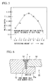
- a graph shown in FIG. 5 shows the result of relationship between the defocusing amount Lf (mm) in the focal point and the melting depth (mm).
- the defocus amount indicates a shift amount between the position of the focal point in an optical system which is manufactured and a surface of object which is welded.
- the defocus amount is 0 (zero) when the position of the focal point in an optical system which is manufactured and a surface of object which is welded coincide.
- the defocus amount is indicated minus under condition that a position of the focal point in the optical system is more inner than a surface of an object which is welded.
- the welding operation is performed under the above conditions.
- a member which has more superior welding characteristics than a base member of the turbine blade main body 51 for a tip plug 56 which plugs the hole 55 on the blade tip section 52 on the gas turbine blade main body 51 in order to restrict the occurrence of the solidification cracking in the welding section, a member which has more superior welding characteristics than a base member of the turbine blade main body 51 for a tip plug 56 which plugs the hole 55 on the blade tip section 52 on the gas turbine blade main body 51.
- the laser beam is precisely disposed in a border line between the base member for the blade tip section 52 of the turbine blade main body 51 in the butt-welding section 57 and the tip plug 56 such that dilution ratio of the base member for the blade tip section 52 of the turbine blade main body 51 in the butt-welding section 57 and the dilution ratio of the tip plug 56 should be approximately 50 %.
- the dilution ration can be defined such as [Area of melting section in the base member for the blade tip section]/[Area of melting section in the base member for the blade tip section + Area of melting section in the tip plug].
- alloys such as a Nickel-base super alloy Inconel 625 (Cr: 21 to 23 weight %, Mo: 8 to 10 weight %, the rest of the alloy is Ni, Inconel is a Trademark registered by Inconel Corp.) which contains very few Al and Ti which do not contain can be named in contrast to a fact in which a Nickel-base super alloy Inconel 738 (Al: 35 weight %, Ti: 3.2 weight %, the rest of the alloy is Ni) which is quite commonly used for a member for the turbine blade base body 51.
- a Nickel-base super alloy Inconel 625 Cr: 21 to 23 weight %, Mo: 8 to 10 weight %, the rest of the alloy is Ni
- Inconel is a Trademark registered by Inconel Corp.
- FIG. 6 a cross section in a welding metal section is shown in which a tip plug 56 is welded to a hole 55 on a blade tip section 52 on the turbine blade main body 51 made of Inconel 738 by performing a butt-welding operation with 50 % of dilution ratio by using a Nickel-base super alloy Inconel 625 for a tip plug 56.
- a tip plug 56 is capped on a protruding boss section 55a which is formed on the hole 55 and fitted thereto by performing a laser welding operation.
- Small porosity p having no more than 0.25 mm of diameter is found in a butt-welding section in the welding metal section. Even though a crack occurs, it remains in the base member (boss section 55a in the hole 55) for the blade tip section 52; thus, a crack does not occur in the tip plug 56.
- a liquefaction crack which occurs in a heat-affected zone (hereinafter called "HAZ"") caused in a heating operation for the base member for the blade tip section 52 is large in a welding direction. Therefore, such a liquation cracking occurs radially with respect to the bead.
- the liquefaction crack does not grow against the stress which is applied to the tip plug 56.
- the strength in the welded metal is weaker than the strength in the tip blade; thus, such a crack occurs inside of the welded metal. That is, such a crack does not affect the strength in the entire structure of the turbine blade substantially even if a fine HAZ crack occurs.
- a hole 55 on the blade tip section 52 of the turbine blade main body 51 formed by MGA1400DS member is plugged by the tip plug 56 made of a Nickel- base super alloy Inconel 625 by performing a YAG laser butt-welding operation in such a manner as shown in FIGS. 7A and 7B.
- Parameters in this embodiment are as follows.
- a tip plug 56 made according to the above specification is put on a protruding boss section 55a on the hole 55 and fitted to the hole 55 for testing a fatigue strength in such a manner as shown in FIGS. 7A (plan view) and 7B (side view). Furthermore, a laser butt-welding operation is performed under the above condition.
- the welding condition is set to be the above preferable condition. The rest of the parameters are as follows.
- Welding Device A device which is formed by assembling an SI optical fiber having 0.6 mm of core diameter and an optical system having 80 mm of focal length is used for a YAG laser oscillator having 1.2 kW of output. Other conditions are such as output: 800 W, pulse width: 12.5 ms, Duty: 50 %, repetition 40 pps, defocusing amount Lf: -0.5 mm, welding speed: 1.0 m/min, entering heat amount: 480J/cm.
- a hole 55 is plugged by a tip plug 56 by performing a laser butt-welding operation.
- Fatigue strength in such a welded member is tested in manners shown in FIGS. 7A and 7B.
- a crack and penetration fatigue life Nf (cycle) against a load stress ⁇ ⁇ (kgf/mm 2 ) is measured.
- Test is conducted according to the above test parameters.
- a crack and penetration fatigue life Nf (cycle) against a load stress ⁇ ⁇ (kgf/mm 2 ) is measured in the load applying cycle.
- a test piece is made by plugging the hole 55 by the tip plug 56 by using the ⁇ blade tip section 52>, ⁇ tip plug 56> having the similar specification to the above explained specification by performing the TIG butt-welding operation.
- a test for fatigue strength is performed under the similar conditions and the result is shown in a graph in FIG. 8 for so as to compare the results each other.
- the crack and penetration fatigue life Nf (cycle) which is observed by performing a method for the laser butt-welding according to the present invention is higher than any load stress ⁇ ⁇ (kgf/mm 2 ) obtained by a TIG welding method.
- the crack and penetration fatigue life Nf (cycle) which is observed in the laser butt-welding method according to the present invention is three times as high as the crack and penetration fatigue life Nf (cycle) according to the TIG welding method. That is, a low cycle fatigue (hereinafter called "LCF") life characteristics improves three times as high as that in a conventional TIG welding method.
- LCF low cycle fatigue
- the position where the crack occurs in the crack and penetration fatigue life is on a tip of an arc forming curve R section in any case of the above test.
- factors such as a member for forming a tip plug, a welding condition, an entering heat amount, defocus amount of the laser beam, a dilution ratio for a member for forming a tip plug which is plugged in the blade tip section are preferably set when a tip plug is fit to the hole and the hole is plugged by performing a laser butt-welding operation. Therefore, it is possible to simplify the welding process and also it is possible to prevent the solidification cracking and the liquation cracking in the welded metal reliably.
- the hole is plugged by the tip plug by performing the butt-welding operation; therefore, the stress in a direction orthogonal to the longitudinal direction of the blade main body is received in a pulling direction; thus, the strength under the above condition is stronger than the strength in case in which the stress corresponding to the above stress is received in a shearing direction in an attaching welding method. Also, it is possible to improve the LCF fatigue lilfe three times as long as that of the conventional TIG welding method.
- a method using a laser welding operation is employed. Therefore, it is possible to perform the method by an automation device such as a welding device which is provided with an numerical control (hereinafter called NC) device. Therefore, it is possible to perform the welding process in high accuracy repeatedly in high quality efficiently. Thus, there is an effect in that the product yield increases so as to enhance the production efficiency.
- NC numerical control
- a plug is strengthened by welding the plug to a bottom plate section (55a in FIG. 3) to which the plug is fitted; thus, it is important to control the thickness of the bottom plate appropriately. Thickness in such a bottom plate depends on a position of a core which is used in a process for casting a blade. That is, there is a problem in that it is difficult to control the thickness of the bottom plate because this thickness dimension may become thick or thin. In contrast, according to a method for the butt-welding operation, it is possible to maintain the strength in the butt-welded section; therefore, it is not necessary to control the thickness of the bottom plate.
Landscapes
- Engineering & Computer Science (AREA)
- Mechanical Engineering (AREA)
- General Engineering & Computer Science (AREA)
- Physics & Mathematics (AREA)
- Optics & Photonics (AREA)
- Chemical & Material Sciences (AREA)
- Combustion & Propulsion (AREA)
- Plasma & Fusion (AREA)
- Architecture (AREA)
- Laser Beam Processing (AREA)
- Turbine Rotor Nozzle Sealing (AREA)
Applications Claiming Priority (3)
| Application Number | Priority Date | Filing Date | Title |
|---|---|---|---|
| JP2001260134A JP2003065068A (ja) | 2001-08-29 | 2001-08-29 | ガスタービン翼頂部の加工孔閉塞方法 |
| JP2001260134 | 2001-08-29 | ||
| PCT/JP2002/008730 WO2003018976A1 (en) | 2001-08-29 | 2002-08-29 | Method of closing working hole in gas turbine blade top |
Publications (3)
| Publication Number | Publication Date |
|---|---|
| EP1422402A1 true EP1422402A1 (de) | 2004-05-26 |
| EP1422402A8 EP1422402A8 (de) | 2005-10-26 |
| EP1422402A4 EP1422402A4 (de) | 2009-12-02 |
Family
ID=19087378
Family Applications (1)
| Application Number | Title | Priority Date | Filing Date |
|---|---|---|---|
| EP02770174A Withdrawn EP1422402A4 (de) | 2001-08-29 | 2002-08-29 | Verfahren zum schliessen einer arbeitsbohrung in der oberseite einer gasturbinenschaufel |
Country Status (5)
| Country | Link |
|---|---|
| US (1) | US6984801B2 (de) |
| EP (1) | EP1422402A4 (de) |
| JP (1) | JP2003065068A (de) |
| CN (1) | CN1262748C (de) |
| WO (1) | WO2003018976A1 (de) |
Cited By (6)
| Publication number | Priority date | Publication date | Assignee | Title |
|---|---|---|---|---|
| EP1806477A2 (de) | 2006-01-06 | 2007-07-11 | United Technologies Corporation | Aufspannvorrichtung zur Reparatur eines Turbinenelements |
| WO2009121716A1 (de) * | 2008-03-31 | 2009-10-08 | Alstom Technology Ltd | Schaufel für eine gasturbine |
| EP2028342A3 (de) * | 2007-08-21 | 2011-11-30 | United Technologies Corporation | Verfahren zur Reparatur einer Turbinenschaufelspitze |
| FR2978078A1 (fr) * | 2011-07-22 | 2013-01-25 | Snecma | Procede de fixation d'un element metallique sur une piece en alliage metallique monocristallin de turbomachine |
| DE102013214932A1 (de) * | 2013-07-30 | 2015-02-05 | MTU Aero Engines AG | Verfahren zum Herstellen einer Turbomaschinenschaufel |
| WO2020244691A1 (de) * | 2019-06-07 | 2020-12-10 | MTU Aero Engines AG | Verfahren zum herstellen eines impulskörpermoduls für eine gasturbine, impulskörpermodul, gasturbinenschaufel und verwendung eines impulskörpermoduls |
Families Citing this family (24)
| Publication number | Priority date | Publication date | Assignee | Title |
|---|---|---|---|---|
| FR2852999B1 (fr) * | 2003-03-28 | 2007-03-23 | Snecma Moteurs | Aube allegee de turbomachine et son procede de fabrication |
| US7816625B2 (en) * | 2003-10-06 | 2010-10-19 | Siemens Aktiengesellschaft | Method for the production of a hole and device |
| DE102004006154A1 (de) * | 2004-02-07 | 2005-08-25 | Mtu Aero Engines Gmbh | Verfahren zum Verbinden von Bauteilen |
| US20090320288A1 (en) * | 2008-06-30 | 2009-12-31 | Caterpillar Inc. | Method for repairing a turbine |
| US8510925B2 (en) | 2008-09-04 | 2013-08-20 | Rolls-Royce Corporation | System and method for sealing vacuum in hollow fan blades |
| US8987629B2 (en) * | 2009-07-29 | 2015-03-24 | General Electric Company | Process of closing an opening in a component |
| JP2011161506A (ja) * | 2010-02-15 | 2011-08-25 | Toyota Motor Corp | 溶接方法 |
| JP5881369B2 (ja) | 2011-10-27 | 2016-03-09 | 三菱重工業株式会社 | タービン動翼及びこれを備えたガスタービン |
| EP2591872A1 (de) * | 2011-11-11 | 2013-05-15 | Siemens Aktiengesellschaft | Umschmelzverfahren und anschließendes Auffüllen und Bauteil |
| CN104038305A (zh) * | 2013-03-05 | 2014-09-10 | 住友电气工业株式会社 | 封装部件、光设备封装构造体、封装部件的制造方法及光设备封装构造体的制造方法 |
| EP2808487B1 (de) | 2013-05-29 | 2017-11-08 | Ansaldo Energia IP UK Limited | Verfahren zum Verschließen einer Öffnung auf einer Schaufel einer Gasturbine |
| JP6071760B2 (ja) * | 2013-05-31 | 2017-02-01 | 三菱重工業株式会社 | タービン翼およびその製造方法 |
| EP3090134B1 (de) * | 2013-12-30 | 2019-11-13 | United Technologies Corporation | Fanschaufel mit fussdurchgangslöchern |
| US20150314403A1 (en) * | 2014-05-01 | 2015-11-05 | Siemens Energy, Inc. | Arrangement for laser processing of turbine component |
| JP6521050B2 (ja) * | 2015-02-16 | 2019-05-29 | 株式会社タダノ | 液圧シリンダ、シリンダ装置、作業車両、及び液圧シリンダ製造方法 |
| CN107405721B (zh) * | 2015-03-19 | 2019-12-06 | 爱信艾达株式会社 | 接合部件及其制造方法 |
| MX2018001077A (es) * | 2015-07-28 | 2018-05-17 | Nippon Steel & Sumitomo Metal Corp | Junta soldada por arco en angulo y metodo para producir la misma. |
| EP3645943B1 (de) * | 2017-06-29 | 2021-08-11 | Siemens Energy Global GmbH & Co. KG | Verfahren zur konstruktion von prall-/effuisionskühleigenschaften in einem bauteil einer gasturbine, und übergangskanal einer gasturbine mit durch das verfahren hergestellte prall-/effuisionskühleigenschaften |
| US10618128B2 (en) | 2017-07-18 | 2020-04-14 | General Electric Company | Method for closing a hole in a metal article |
| JP2020055024A (ja) * | 2018-10-03 | 2020-04-09 | トヨタ自動車株式会社 | ステータコイルのレーザ溶接方法 |
| JP7264717B2 (ja) * | 2019-05-15 | 2023-04-25 | ファナック株式会社 | ステータコアの端面に固定されるハウジングを備える電動機 |
| CN113275752A (zh) * | 2021-05-06 | 2021-08-20 | 中国第一汽车股份有限公司 | 一种汽车离合器外壳体总成复合连接方法 |
| CN116810143A (zh) * | 2023-05-26 | 2023-09-29 | 四川工程职业技术学院 | 一种增材制造高温合金的激光焊接方法 |
| KR102942234B1 (ko) * | 2023-11-14 | 2026-03-19 | 두산에너빌리티 주식회사 | 브레이징 플러그 및 이를 이용한 가스터빈 부품 제조방법 |
Family Cites Families (13)
| Publication number | Priority date | Publication date | Assignee | Title |
|---|---|---|---|---|
| JPH01107973A (ja) * | 1987-10-21 | 1989-04-25 | Hitachi Ltd | 翼の製作方法 |
| FR2637210B1 (fr) * | 1988-09-30 | 1990-11-09 | Thomson Hybrides Microondes | Procede de soudure par faisceau laser de deux pieces metalliques, et boitier electronique soude par ce procede |
| FR2695163B1 (fr) * | 1992-09-02 | 1994-10-28 | Snecma | Aube creuse pour turbomachine et son procédé de fabrication. |
| US5554837A (en) * | 1993-09-03 | 1996-09-10 | Chromalloy Gas Turbine Corporation | Interactive laser welding at elevated temperatures of superalloy articles |
| JPH0852512A (ja) * | 1994-08-09 | 1996-02-27 | Sumitomo Metal Ind Ltd | 溶接管の製造方法 |
| JPH08278029A (ja) * | 1995-02-06 | 1996-10-22 | Toshiba Corp | 燃焼器用ライナー及びその製造方法 |
| JPH08224679A (ja) * | 1995-02-22 | 1996-09-03 | Mazda Motor Corp | レーザ溶接方法およびその装置 |
| JPH09168927A (ja) * | 1995-12-19 | 1997-06-30 | Hitachi Ltd | ガスタービン用動翼,静翼の補修方法 |
| JP3908838B2 (ja) * | 1997-09-30 | 2007-04-25 | 昭和電工株式会社 | アルミニウム容器及びその製造方法 |
| JP2001090502A (ja) * | 1999-09-24 | 2001-04-03 | Toshiba Corp | ガスタービン翼の製造方法 |
| US6302649B1 (en) * | 1999-10-04 | 2001-10-16 | General Electric Company | Superalloy weld composition and repaired turbine engine component |
| US6333484B1 (en) * | 2000-03-17 | 2001-12-25 | Chromalloy Gas Turbine Corporation | Welding superalloy articles |
| EP1219381A1 (de) * | 2000-12-27 | 2002-07-03 | Siemens Aktiengesellschaft | Verfahren zum Laserschweissen eines Werkstückes |
-
2001
- 2001-08-29 JP JP2001260134A patent/JP2003065068A/ja active Pending
-
2002
- 2002-08-29 WO PCT/JP2002/008730 patent/WO2003018976A1/ja not_active Ceased
- 2002-08-29 CN CNB028058062A patent/CN1262748C/zh not_active Expired - Lifetime
- 2002-08-29 EP EP02770174A patent/EP1422402A4/de not_active Withdrawn
- 2002-08-29 US US10/467,179 patent/US6984801B2/en not_active Expired - Lifetime
Cited By (8)
| Publication number | Priority date | Publication date | Assignee | Title |
|---|---|---|---|---|
| EP1806477A2 (de) | 2006-01-06 | 2007-07-11 | United Technologies Corporation | Aufspannvorrichtung zur Reparatur eines Turbinenelements |
| EP1806477A3 (de) * | 2006-01-06 | 2010-09-08 | United Technologies Corporation | Aufspannvorrichtung zur Reparatur eines Turbinenelements |
| US8376211B2 (en) | 2006-01-06 | 2013-02-19 | United Technologies Corporation | Turbine element repair fixture |
| EP2028342A3 (de) * | 2007-08-21 | 2011-11-30 | United Technologies Corporation | Verfahren zur Reparatur einer Turbinenschaufelspitze |
| WO2009121716A1 (de) * | 2008-03-31 | 2009-10-08 | Alstom Technology Ltd | Schaufel für eine gasturbine |
| FR2978078A1 (fr) * | 2011-07-22 | 2013-01-25 | Snecma | Procede de fixation d'un element metallique sur une piece en alliage metallique monocristallin de turbomachine |
| DE102013214932A1 (de) * | 2013-07-30 | 2015-02-05 | MTU Aero Engines AG | Verfahren zum Herstellen einer Turbomaschinenschaufel |
| WO2020244691A1 (de) * | 2019-06-07 | 2020-12-10 | MTU Aero Engines AG | Verfahren zum herstellen eines impulskörpermoduls für eine gasturbine, impulskörpermodul, gasturbinenschaufel und verwendung eines impulskörpermoduls |
Also Published As
| Publication number | Publication date |
|---|---|
| EP1422402A8 (de) | 2005-10-26 |
| US6984801B2 (en) | 2006-01-10 |
| CN1262748C (zh) | 2006-07-05 |
| CN1494633A (zh) | 2004-05-05 |
| EP1422402A4 (de) | 2009-12-02 |
| US20040169022A1 (en) | 2004-09-02 |
| WO2003018976A1 (en) | 2003-03-06 |
| JP2003065068A (ja) | 2003-03-05 |
Similar Documents
| Publication | Publication Date | Title |
|---|---|---|
| US6984801B2 (en) | Method of closing a hole in a gas turbine blade top by laser welding | |
| JP5736135B2 (ja) | 第1及び第2のフィラー金属の二重レーザビーム溶接方法 | |
| EP3296052B1 (de) | Schweissvorrichtung und verfahren zur schweissqualitätsprüfung | |
| CN100420537C (zh) | 焊接修复部件的方法 | |
| JP5602458B2 (ja) | タングステン−不活性ガス溶接法によって2つの金属部分を結合するための方法ならびに該方法を実施するための装置 | |
| EP0098306A1 (de) | Schweissverfahren mittels laserstrahl | |
| US11786989B2 (en) | Method for splash-free welding, in particular using a solid-state laser | |
| JP2012228715A (ja) | レーザ溶接装置およびレーザ溶接方法 | |
| JP6137161B2 (ja) | アルミニウム合金製鋳造品の補修方法 | |
| US20200009686A1 (en) | Laser welding method | |
| WO2021131560A1 (ja) | 接合方法 | |
| JP2018167320A (ja) | レーザ肉盛溶接装置、レーザ肉盛溶接方法、および溶接補修方法 | |
| JP4801629B2 (ja) | 筒体壁面の貫通孔製造方法及び筒体構造 | |
| JP2003185777A (ja) | 沸騰水型原子炉用制御棒の製造方法及び沸騰水型原子炉用制御棒 | |
| JP5158924B2 (ja) | レーザ突合せ溶接における溶接可否およびルートギャップ適否判定方法 | |
| CN112276353A (zh) | 焊接方法 | |
| JP4818297B2 (ja) | ガスタービン部品の補修方法及びガスタービン部品 | |
| JP6671129B2 (ja) | シャント抵抗器の製造方法、および溶接済み板材の製造装置 | |
| JP2012228716A (ja) | レーザ溶接装置およびレーザ溶接方法 | |
| JP2020040106A (ja) | 異材接合方法 | |
| JP2001090502A (ja) | ガスタービン翼の製造方法 | |
| US12409503B2 (en) | Method for welding half coil of reactor | |
| EP1925391A1 (de) | Laser-Kehlnahtschweißung | |
| JP2026004894A (ja) | 突合せ溶接方法 | |
| JP2026004893A (ja) | レーザー溶接装置、レーザー溶接方法及び加工用プログラム生成方法 |
Legal Events
| Date | Code | Title | Description |
|---|---|---|---|
| PUAI | Public reference made under article 153(3) epc to a published international application that has entered the european phase |
Free format text: ORIGINAL CODE: 0009012 |
|
| 17P | Request for examination filed |
Effective date: 20030811 |
|
| AK | Designated contracting states |
Kind code of ref document: A1 Designated state(s): AT BE BG CH CY CZ DE DK EE ES FI FR GB GR IE IT LI LU MC NL PT SE SK TR |
|
| RIN1 | Information on inventor provided before grant (corrected) |
Inventor name: UEMURA, YOSHITAKA,MITSUBISHI HEAVY INDUSTRIES LTD Inventor name: MEGA, MASAHIKO,MITSUBISHI HEAVY INDUSTRIES LTD Inventor name: KANIKAWA, MASAYA,MITSUBISHI HEAVY INDUSTRIES LTD Inventor name: TAKAHASHI, KOJI,MITSUBISHI HEAVY INDUSTRIES LTD Inventor name: TSUNATANI, TOSHIHIKO,MITSUBISHI HEAVY IND. LTD Inventor name: OHARA, MINORU,MITSUBISHI HEAVY INDUSTRIES LTD Inventor name: FUJITA, KEN,MITSUBISHI HEAVY INDUSTRIES, LTD Inventor name: YAMAGUCHI, KENGO,MITSUBISHI HEAVY INDUSTRIES LTD Inventor name: TSUBATA, SYUHO,MITSUBISHI HEAVY INDUSTRIES, LTD |
|
| RIN1 | Information on inventor provided before grant (corrected) |
Inventor name: FUJITA, KEN,MITSUBISHI HEAVY INDUSTRIES, LTD Inventor name: TSUBOTA, SYUHO,MITSUBISHI HEAVY INDUSTRIES, LTD Inventor name: TAKAHASHI, KOJI,MITSUBISHI HEAVY INDUSTRIES LTD Inventor name: MEGA, MASAHIKO,MITSUBISHI HEAVY INDUSTRIES LTD Inventor name: TSUNATANI, TOSHIHIKO,MITSUBISHI HEAVY IND. LTD Inventor name: UEMURA, YOSHITAKA,MITSUBISHI HEAVY INDUSTRIES LTD Inventor name: OHARA, MINORU,MITSUBISHI HEAVY INDUSTRIES LTD Inventor name: KANIKAWA, MASAYA,MITSUBISHI HEAVY INDUSTRIES LTD Inventor name: YAMAGUCHI, KENGO,MITSUBISHI HEAVY INDUSTRIES LTD |
|
| RIN1 | Information on inventor provided before grant (corrected) |
Inventor name: YAMAGUCHI, KENGO,MITSUBISHI HEAVY INDUSTRIES LTD Inventor name: MEGA, MASAHIKO,MITSUBISHI HEAVY INDUSTRIES LTD Inventor name: UEMURA, YOSHITAKA,MITSUBISHI HEAVY INDUSTRIES LTD Inventor name: KANIKAWA, MASAYA,MITSUBISHI HEAVY INDUSTRIES LTD Inventor name: OHARA, MINORU,MITSUBISHI HEAVY INDUSTRIES LTD Inventor name: TAKAHASHI, KOJI,MITSUBISHI HEAVY INDUSTRIES LTD Inventor name: TSUBOTA, SYUHO,MITSUBISHI HEAVY INDUSTRIES, LTD Inventor name: TSUNATANI, TOSHIHIKO,MITSUBISHI HEAVY IND. LTD Inventor name: FUJITA, KEN,MITSUBISHI HEAVY INDUSTRIES, LTD |
|
| A4 | Supplementary search report drawn up and despatched |
Effective date: 20091103 |
|
| 17Q | First examination report despatched |
Effective date: 20100429 |
|
| STAA | Information on the status of an ep patent application or granted ep patent |
Free format text: STATUS: THE APPLICATION IS DEEMED TO BE WITHDRAWN |
|
| 18D | Application deemed to be withdrawn |
Effective date: 20100910 |