EP1421896A2 - Système de contrôle pour un appareil de mesure d' informations du corps vivant - Google Patents
Système de contrôle pour un appareil de mesure d' informations du corps vivant Download PDFInfo
- Publication number
- EP1421896A2 EP1421896A2 EP03257236A EP03257236A EP1421896A2 EP 1421896 A2 EP1421896 A2 EP 1421896A2 EP 03257236 A EP03257236 A EP 03257236A EP 03257236 A EP03257236 A EP 03257236A EP 1421896 A2 EP1421896 A2 EP 1421896A2
- Authority
- EP
- European Patent Office
- Prior art keywords
- living body
- body information
- information detecting
- data
- detecting terminal
- Prior art date
- Legal status (The legal status is an assumption and is not a legal conclusion. Google has not performed a legal analysis and makes no representation as to the accuracy of the status listed.)
- Withdrawn
Links
Images


Classifications
-
- A—HUMAN NECESSITIES
- A61—MEDICAL OR VETERINARY SCIENCE; HYGIENE
- A61B—DIAGNOSIS; SURGERY; IDENTIFICATION
- A61B5/00—Measuring for diagnostic purposes; Identification of persons
- A61B5/02—Detecting, measuring or recording pulse, heart rate, blood pressure or blood flow; Combined pulse/heart-rate/blood pressure determination; Evaluating a cardiovascular condition not otherwise provided for, e.g. using combinations of techniques provided for in this group with electrocardiography or electroauscultation; Heart catheters for measuring blood pressure
- A61B5/0205—Simultaneously evaluating both cardiovascular conditions and different types of body conditions, e.g. heart and respiratory condition
-
- A—HUMAN NECESSITIES
- A61—MEDICAL OR VETERINARY SCIENCE; HYGIENE
- A61B—DIAGNOSIS; SURGERY; IDENTIFICATION
- A61B5/00—Measuring for diagnostic purposes; Identification of persons
- A61B5/0002—Remote monitoring of patients using telemetry, e.g. transmission of vital signals via a communication network
-
- G—PHYSICS
- G16—INFORMATION AND COMMUNICATION TECHNOLOGY [ICT] SPECIALLY ADAPTED FOR SPECIFIC APPLICATION FIELDS
- G16H—HEALTHCARE INFORMATICS, i.e. INFORMATION AND COMMUNICATION TECHNOLOGY [ICT] SPECIALLY ADAPTED FOR THE HANDLING OR PROCESSING OF MEDICAL OR HEALTHCARE DATA
- G16H40/00—ICT specially adapted for the management or administration of healthcare resources or facilities; ICT specially adapted for the management or operation of medical equipment or devices
- G16H40/60—ICT specially adapted for the management or administration of healthcare resources or facilities; ICT specially adapted for the management or operation of medical equipment or devices for the operation of medical equipment or devices
- G16H40/67—ICT specially adapted for the management or administration of healthcare resources or facilities; ICT specially adapted for the management or operation of medical equipment or devices for the operation of medical equipment or devices for remote operation
-
- G—PHYSICS
- G16—INFORMATION AND COMMUNICATION TECHNOLOGY [ICT] SPECIALLY ADAPTED FOR SPECIFIC APPLICATION FIELDS
- G16H—HEALTHCARE INFORMATICS, i.e. INFORMATION AND COMMUNICATION TECHNOLOGY [ICT] SPECIALLY ADAPTED FOR THE HANDLING OR PROCESSING OF MEDICAL OR HEALTHCARE DATA
- G16H10/00—ICT specially adapted for the handling or processing of patient-related medical or healthcare data
- G16H10/60—ICT specially adapted for the handling or processing of patient-related medical or healthcare data for patient-specific data, e.g. for electronic patient records
-
- G—PHYSICS
- G16—INFORMATION AND COMMUNICATION TECHNOLOGY [ICT] SPECIALLY ADAPTED FOR SPECIFIC APPLICATION FIELDS
- G16H—HEALTHCARE INFORMATICS, i.e. INFORMATION AND COMMUNICATION TECHNOLOGY [ICT] SPECIALLY ADAPTED FOR THE HANDLING OR PROCESSING OF MEDICAL OR HEALTHCARE DATA
- G16H40/00—ICT specially adapted for the management or administration of healthcare resources or facilities; ICT specially adapted for the management or operation of medical equipment or devices
- G16H40/60—ICT specially adapted for the management or administration of healthcare resources or facilities; ICT specially adapted for the management or operation of medical equipment or devices for the operation of medical equipment or devices
- G16H40/63—ICT specially adapted for the management or administration of healthcare resources or facilities; ICT specially adapted for the management or operation of medical equipment or devices for the operation of medical equipment or devices for local operation
Definitions
- the present invention relates to a living body information detecting terminal control system which detects living body information of a user in his or her daily life regardless of normal/abnormal conditions and is useful for home health care and emergency notification.
- a portable terminal that detects living body information and a living body information monitoring device that receives data transmitted from the portable terminal and performs processing on the data, in which the living body information and an emergency signal transmitted from the living body information monitoring device are received by an external host server via a public line to thereby accumulate data and respond to the emergency situation.
- JP 2001-93068 A pages 5 and 6, Fig. 1
- a human body abnormality detecting communication terminal including: a moisture absorption detector A that detects falling of a wearer of the terminal (hereinafter simply referred to as the "wearer") into a river or a bathtub; an inclination detector C that detects tumbling of a human body; a human body wearing state detector B that detects a wearing state of the terminal by measuring a body temperature on a human body surface; and a human body abnormality judgement detector that operates a blood oxygen measuring device only when judging an abnormality from the respective outputs of the moisture absorption detector A and the human body wearing state detector B or from the respective outputs of the inclination detector C and the human body wearing state detector B, and when the obtained measurement output is abnormal, notifies this to a security service via a telephone line (see JP 2001-93068 A).
- the system including the human body abnormality judgement detector and the human body abnormality detecting communication terminal that are described above is subject to the following problem. That is, the moisture absorption detector A, the human body wearing state detector B, and the inclination detector C which serve as triggers and transmit trigger signals, and control means for detecting the trigger signals to generate a control signal for operating the blood oxygen measuring device, are constructed as the same single terminal.
- the measurement output indicates no signal or a normal value even under an abnormal condition due to such factors as a breakdown of the blood oxygen measuring device or the control means, the abnormal condition is not communicated to the security service, rendering the system rather poor in terms of reliability.
- the present invention has been made in view of the above-mentioned problems, and therefore has an object of the invention to provide a living body information detecting terminal control system including: a portable type living body information detecting terminal for temporarily storing a first data as a signal or transmitting the signal to the exterior as a first transmission data, the first data being constituted by a living body digital signal obtained by performing an A/D conversion on living body information detected by living body information detecting sensors or by a first processed data obtained by performing data processing on the living body digital signal; a living body information monitoring device for receiving the first transmission data transmitted from the living body detecting terminal and for temporarily storing a second data as a signal or transmitting the signal to the exterior as a second transmission data via a public line, the second data being constituted by a second processed data obtained by performing processing on the first data contained in the first transmission data or by the living body digital information; and a host server for receiving the second transmission data transmitted from the living body information monitoring device via the public line and for displaying or storing the second transmission data.
- the living body information detecting terminal control system is configured such that the living body information detecting terminal and the living body information monitoring device are capable of performing bidirectional communication with each other and that the living body information monitoring device controls the operation of the living body information detecting terminal by using, as a trigger, the signal received from the living body information detecting terminal. Accordingly, with the living body information detecting terminal control system according to the present invention, the drive conditions of the sensors provided to the living body information detecting terminal can be controlled from, for example, the living body information detecting device side.
- the first transmission data is at least one of a first normal-time transmission data and a first abnormal-time transmission data.
- the first normal-time transmission data is constituted by at least one of the first data and identification information that is specific to the wearer and recorded in the living body information detecting terminal.
- the first abnormal-time transmission data is constituted by the first data, the identification information that is specific to the wearer and recorded in the living body information detecting terminal, and a signal indicating occurrence of an abnormality.
- the second transmission data is at least one of a second normal-time transmission data and a second abnormal-time transmission data.
- the second normal-time transmission data is similarly constituted by at least one of the second data, the identification information that is specific to the wearer and recorded in the living body information monitoring device, and identification information for the device.
- the second abnormal-time transmission data is constituted by at least one of the second data, the identification information that is specific to the wearer and recorded in the living body information monitoring device, the identification information for the device, and the signal indicating occurrence of an
- the living body information detecting terminal records a preset value range for the first data, and may be endowed with: a normal-time living body information transmitting function for temporarily storing the first data or transmitting the data to the living body information monitoring device at regular time intervals when the first data is within the preset value range; and an abnormal-time automatically notifying function for immediately performing communication with the outside when the first data is not within the preset value range.
- the living body information monitoring device can receive the identification information that is specific to the wearer and stored in the living body information detecting terminal and send a control signal to the living body information detecting terminal by selecting, from among the living body information detecting sensors provided to the living body information detecting terminal, a first living body information detecting sensor that is driven under normal conditions or a second living body information detecting sensor that is in a power-save state or driven intermittently under normal conditions.
- the selection between the first living body information detecting sensor and the second living body information detecting sensor and the sending of the control signal may be performed by the living body information detecting terminal.
- the living body information monitoring device can transmit to the living body information detecting terminal a control signal for driving the second living body information detecting sensor that is in a power-save state during the normal conditions.
- the living body information monitoring device may perform control on a measuring interval, a measuring time, and a data sampling frequency for the second living body information detecting sensor.
- first living body information detecting sensor and the second living body information detecting sensor may be controlled by the living body information detecting terminal.
- At least one call button is provided to the living body information detecting terminal or the living body information monitoring device. With pressing of the call button as a trigger, it is possible to perform the selection between the first living body information detecting sensor and the second living body information detecting sensor, and the control of the drive condition and the measurement operation of the second living body information detecting sensor.
- the living body information monitoring device can send, to the living body information detecting terminal, operation verification signals verifying the breakdown conditions or drive conditions of the respective sensors provided to the living body information monitoring device, and the living body information detecting terminal having received the operation verification signals can verify the breakdown conditions and the drive conditions and send them to the living body information monitoring device.
- the host server may be the host server that sends: the control signal for controlling the living body information detecting terminal by determining between the first living body information detecting sensor and the second living body information detecting sensor; the control signal for controlling the living body information detecting terminal by determining the drive condition and the measurement operation of the second living body information detecting sensor, which is in a power-save state or driven intermittently during normal conditions, based on an output from the first living body information detecting sensor that is driven under normal conditions; and the control signal for verifying the breakdown condition and the drive condition of the second living body information detecting sensor that is in a power-save state or driven intermittently during normal conditions.
- a living body information detecting terminal control system including:
- a living body information detecting terminal control system including:
- a living body information detecting terminal control system in which the living body information detecting terminal further includes:
- a living body information detecting terminal control system in which:
- a living body information detecting terminal control system in which the living body digital signal control unit of the living body information detecting terminal includes:
- a living body information detecting terminal control system in which the living body information detecting terminal further includes an abnormal-time living body information transmitting function for:
- a living body information detecting terminal control system in which the living body information detecting terminal further includes:
- a living body information detecting terminal control system in which the living body information detecting terminal further includes:
- a living body information detecting terminal control system in which, in a case where an output value of the first living body information data judging unit is an abnormal output value, the living body information sensor control unit supplies power to the power-save living body information detecting sensor and drives the power-save living body information detecting sensor.
- a living body information detecting terminal control system in which, in a case where an output value of the first living body information data judging unit is an abnormal output value, the living body information sensor control unit performs control by a control method based on at least one of a measuring interval, a measuring time, and a data sampling frequency for an intermittent driving living body information detecting sensor.
- a living body information detecting terminal control in which the living body information detecting terminal selects a first living body information detecting sensor from the living body information sensors based on an output result from the first living body information data judging unit, and transmits the selection result to the living body information monitoring device through the living body information data transmitter/receiver unit.
- a living body information detecting terminal control system in which the living body information detecting terminal further includes a call button that enables a sensor operation control by being pressed.
- a living body information detecting terminal control system in which the living body information detecting terminal transmits the living body information data to the living body information monitoring device based on the living body information signal detected by the living body information detecting sensor, or controls the drive of the living body information detecting sensor based on an instruction from the living body information detecting terminal itself.
- a living body information detecting terminal control system in which at least one living body information detecting sensor of sensors composing a living body information detecting sensor unit of the living body information detecting terminal is a sensor for detecting a pulse.
- a living body information detecting terminal control system in which at least one living body information detecting sensor of sensors composing a living body information detecting sensor unit of the living body information detecting terminal is a sensor for detecting a blood sugar level or a blood glucose concentration.
- a living body information detecting terminal control system in which at least one living body information detecting sensor of sensors composing a living body information detecting sensor unit of the living body information detecting terminal is a sensor for detecting a moving state of the wearer.
- a living body information monitoring device includes:
- a living body information detecting terminal control system in which:
- a living body information detecting terminal control system in which, in the living body information monitoring device in a case where the second living body information data is judged as being outside the value range preset by the second living body information data judging unit, and the second abnormal-time transmission data is transmitted to the host server:
- a living body information detecting terminal control system in which:
- a living body information detecting terminal control system in which the first living body information detecting terminal control unit further includes:
- a living body information detecting terminal control system in which the first living body information detecting terminal control unit further includes:
- a living body information detecting terminal control system in which the living body information monitoring device further includes a call button that enables operation control of a sensor by being pressed.
- a living body information detecting terminal control system in which the living body information monitoring device performs a sensor operation control in response to a signal detected by the living body information detecting terminal.
- a living body information detecting terminal control system in which, when an output from the first living body information detecting sensor is judged as being outside the preset value range, the living body information sensor control unit within the living body information detecting terminal or the first living body information detecting terminal control unit within the living body information monitoring device performs a control such that a measuring interval of the second living body information detecting sensor becomes shorter than the measuring interval required during normal conditions.
- a living body information detecting terminal control system in which, when an output from the first living body information detecting sensor is judged as being outside the preset value range, the living body information sensor control unit within the living body information detecting terminal or the first living body information detecting terminal control unit within the living body information monitoring device performs a control such that a measuring time of the second living body information detecting sensor becomes longer than the measuring time required during normal conditions.
- a living body information detecting terminal control system in which, when an output from the first living body information detecting sensor is judged as being abnormal, the living body information sensor control unit within the living body information detecting terminal or the first living body information detecting terminal control unit within the living body information monitoring device performs a control such that a data sampling frequency of the second living body information detecting sensor becomes higher than the data sampling frequency required during normal conditions.
- a living body information detecting terminal control system in which the living body information sensor control unit included in the living body information detecting terminal or the first living body information detecting terminal control unit included in the living body information monitoring device causes control of the second living body information detecting sensor to return to a preset reference control state, in a case where an output from the first living body information detecting sensor is judged as being outside the preset value range by the first judging unit or the second judging unit, and the output from the first living body information detecting sensor is again judged as being within the preset value range with respect to the second living body information detecting sensor in which at least one of the measuring interval, the measuring time, and the data sampling frequency is controlled.
- a living body information detecting terminal control system in which the first living body information detecting terminal control unit further includes:
- a living body information detecting terminal control system in which the host server includes:
- a living body information detecting terminal control system in which the second living body information detecting terminal control unit includes:
- a living body information detecting terminal control system in which the second living body information detecting terminal control unit further includes:
- a living body information detecting terminal control system in which, in a case where an output signal from the first living body information detecting sensor exceeds a preset reference value range, or in a case where a difference with respect to an output signal previously outputted from the living body information detecting sensor exceeds a preset variation range, the first judging unit included in the living body information detecting terminal or the second judging unit included in the living body information monitoring device judges the output signal to be abnormal.
- the ON/OFF of the living body information detecting sensors provided to the living body information detecting terminal is controlled from the living body information monitoring device side on the basis of the wearer identification information transmitted from the living body information detecting terminal.
- the living body information detecting terminals provided for this purpose may all be constructed in the same manner, making it possible to simplify the manufacturing process for the living body information detecting terminal.
- the living body information detecting sensors provided to the living body information detecting terminal consist of the first living body information detecting sensor that is driven during normal conditions and the second living body information detecting sensor that is in a power-save state or driven intermittently during normal conditions, and the ON/OFF or the operation of the second living body information detecting sensor is controlled from the living body information monitoring device side in accordance with the output of the first living body information detecting sensor which is transmitted from the living body information detecting terminal.
- the signals for verifying the drive conditions and breakdown conditions of the living body information detecting sensors provided to the living body information detecting terminal are transmitted from the living body information monitoring device side at regular time intervals, thereby making it possible to grasp, in particular, the breakdown condition of the living body information detecting sensor that is in a power-save state or performs measurement in an intermittent manner during normal conditions.
- the living body information detecting sensor is in the breakdown condition when the wearer falls into an abnormal state and it is necessary to drive the living body information detecting sensor that is in a power-save state during normal conditions, thereby making it possible to improve the reliability of the system.
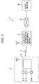
- Fig. 1 is a block diagram showing a configuration of a living body information detecting terminal control system 1 of the present invention.
- the living body information detecting terminal control system 1 of the present invention includes: a living body information detecting terminal 2 which will be described later and has at least one living body information detecting sensors 5-1 to 5-N and processing/transmitting means 6 and which will be described later; a living body information monitoring device 3 which will be described later and receives a first transmission data as a first normal-time transmission data or a first abnormal-time transmission data which is transmitted from the living body information detecting terminal 2; a host server 4 for receiving a second transmission data as a second normal-time transmission data or a second abnormal-time transmission data which is transmitted from the living body information monitoring device 3; bidirectional communication means 7 for establishing communication between the living body information detecting terminal 2 and the living body information monitoring device 3; and a public line 8.
- the living body information detecting terminal 2 may adopt either a form of being carried by a user, or a form of a stationary type.
- the living body information monitoring device 3 may adopt either a form of a portable type or a form of a stationary type.
- the bidirectional communication means 7 may be either of a wireless type or of a wired type irrespective of the communication system as long as the communication is bidirectionally carried out through the bidirectional communication means 7.
- a wireless communication means such as an RFM system or BluetoothTM can be used.
- any public line can be used without a problem, such as a wired telephone line, a mobile phone line, a PHS line, or an optical LAN cable.
- FIG. 2 is a block diagram showing the configuration of the living body information detecting terminal 2. This configuration is an example of a basic form of the living body information detecting terminal in the living body information detecting terminal control system of the present invention.
- the living body information detecting terminal 2 as a constituent element of the living body information detecting terminal control system 1 of the present invention includes: a sensor unit 12 having N sensor groups 5-1 to 5-N (where N is at least 1) for detecting living body information; a connector unit 16 for connecting the sensor unit 12 to a processing/transmitting/receiving unit 6; an A/D converter unit 26 for converting living body information obtained from the sensor unit 12 into a living body digital signal; a first signal control unit 56 for carrying out signal control by performing processing on the living body digital signal to generate a first processed data; a first memory unit 46 including a ROM 46-1 for storing therein data of a previously set value range for the first data consisting of the living body digital signal or the first processed data, and identification information specific to a wearer, and a RAM 46-2 for temporarily storing therein the first data; a sensor control unit 66 for controlling the living body information detecting sensors of the sensor unit 12 in accordance with a request or a command issued from the outside; a
- any sensors may be applied as long as they are sensors for detecting physiological information or movement information of the wearer such as a sphygmomanometer, a blood oxygen saturation measuring instrument, a skin impedance measuring instrument, a sweating amount measuring instrument, a weighing machine, a momentum measuring instrument, a clinical thermometer, and a glucose sensor for measuring a blood glucose concentration.
- sensors for detecting physiological information or movement information of the wearer such as a sphygmomanometer, a blood oxygen saturation measuring instrument, a skin impedance measuring instrument, a sweating amount measuring instrument, a weighing machine, a momentum measuring instrument, a clinical thermometer, and a glucose sensor for measuring a blood glucose concentration.
- a sensor for detecting pulses or acceleration following movement may be used.
- any sensors may be applied as long as they are sensors for detecting pulses or heartbeats to convert the pulses or the heartbeats into an electrical signal, such as a sensor for driving a piezoelectric device as a transducer to transmit an ultrasonic wave to a living body to obtain a reflected wave to detect pulses from the reflected wave, a sensor for converting a heartbeat sound, which is obtained from a detector for detecting heartbeats such as a stethoscope used by a doctor, into an electrical signal to detect heartbeats or pulses, a sensor for detecting pulses at the tip of a finger or an earlobe on the basis of a photoelectric pulse wave system, and a sensor for detecting heartbeats from electrodes worn on the breast.
- a sensor for driving a piezoelectric device as a transducer to transmit an ultrasonic wave to a living body to obtain a reflected wave to detect pulses from the reflected wave a sensor for converting a heartbeat sound, which is obtained from a
- any sensors including a piezoelectric type or an electrostatic type sensor, which are adapted to be able to detect acceleration may be applied.
- an angular velocity or an angular acceleration may be detected in addition to acceleration.
- an identification number specific to the wearer and/or a terminal may be recorded in the ROM 46-1 built in the first memory unit 46.
- personal information such as an address, a name, age, a telephone number, a blood group, and anamnesis of a wearer, and a name and a contact address of a family doctor, data on the timing with which the first data detected by the sensor unit 12 and temporarily stored in the RAM 46-2 is transmitted from the first transmitting/receiving unit 76 to the living body information monitoring device or the server provided in the outside, and identification information used to specify the living body information monitoring device or the server as the destination to which the first data is sent may also be recorded in the ROM 46-1 built in the first memory unit 46.
- the first signal control unit 56 is provided with a first data processing function of performing data processing on the living body digital signal, and a normal-time living body information transmitting function of transmitting a first normal-time transmission data, which will be described later, to the outside.
- the first data processing function will hereinbelow be described by giving an actual example.
- the detected living body information is a pulse
- a pulse wave waveform detected by the sensor corresponds to the living body digital signal
- the number of pulses per minute which is obtained by calculating peak intervals of the pulse wave waveform corresponds to the first processed data.
- an acceleration waveform detected by a sensor corresponds to the living body digital signal
- the number of pitches per minute which is obtained by calculating the peak intervals of the acceleration waveform, action information such as falling down of the wearer which is identified on the basis of a waveform, momentum which is calculated on the basis of a waveform, and the like correspond to the first processed data.
- data obtained by performing digital conversion on raw data obtained from the living body information detecting sensor is the living body digital signal, and data obtained as a result of subjecting the living body digital signal to a processing that will be described later is the first processed data.
- Data containing at least any one of the living body digital signal and the first processed data is referred to as the first data.
- a statistical processing for obtaining a mean value, dispersion of data, a maximum value, a minimum value, and the like may be executed at arbitrary time intervals.
- a mathematical processing such as a fast Fourier transform, or a processing such as a waveform analysis may also be executed. The same as described above applies also to a living body digital signal and second processed data constituting a second data that will be described later.
- the first signal control unit 56 has a normal-time living body information transmitting function of carrying out signal control so as to periodically transmit a first normal-time transmission data 010 containing therein at least any one of the first data temporarily stored in RAM 46-2 and the predetermined identification information specific to the wearer which is recorded in ROM 46-1 as the first transmission data, from the first transmitting/receiving unit 76 to the living body information monitoring device or the server provided in the outside in accordance with a predetermined transmission timing which is recorded in the ROM 46-1.
- the first normal-time transmission data may also be transmitted when a transmission request has been made by the living body information monitoring device or the server provided in the outside.
- the first normal-time transmission may adopt a data structure in which the living body digital signal and the first processed data are continuously recorded for each sensor, for example, a structure in which a living body digital signal 410 from a first sensor, a first processed data 510 from the first sensor, a living body digital signal 610 from a second sensor, and a first processed data 710 from the second sensor are arranged after a header 110, a wearer identification number 210, and a device identification number 310.
- the data structure shown in Fig. 17A is merely one example. Thus, the order of the data shown in Fig. 17A may be changed. Also, as for the data structure, any data structure such as a hierarchical type, a network type, or a relational type structure may be adopted, and hence the data structure is not intended to be limited to the form shown in Figs. 13A to 13C.
- the sensor control unit 66 carries out a control for the sensor groups 5-1 to 5-N included in the sensor unit 12, such that power is constantly supplied to the sensor determined as the first living body information detecting sensor to be driven, and no power is supplied to the sensor determined as the second living body information detecting sensor that is in a power-save state, in accordance with a request made by the external living body information monitoring device or server.
- a determination may also be made such that the sensor control unit 66 performs control for the sensor groups 5-1 to 5-N included in the sensor unit 12 to drive the first living body information detecting sensor is driven at all times, and to intermittently drive the second living body information detecting sensor, in accordance with a request made by the external living body information monitoring device or server.
- the control may also be carried out such that the power is constantly supplied to the first living body information detecting sensor, and the measurement is intermittently carried out according to preset measuring intervals, measuring time and a data sampling frequency using the second living body information detecting sensor.
- the sensor control unit 66 carries out a control for the sensor groups 5-1 to 5-N included in the sensor unit 12 to drive both of the first living body information detecting sensor and the second living body information detecting sensor intermittently in accordance with a request made by the external living body information monitoring device or server.
- the measuring interval of the first living body information detecting sensor is set so as to be equal to or shorter than that of the second living body information detecting sensor
- the measuring time of the first living body information detecting sensor is set so as to be equal to or longer than that of the second living body information detecting sensor
- the data sampling frequency of the first living body information detecting sensor is set so as to be equal to or higher than that of the second living body information detecting sensor.
- Figs. 10A and 10B show waveform charts useful in explaining the measuring intervals, the measuring time, and the data sampling frequency.
- Fig. 10A is one example showing a situation in which data is intermittently measured for a certain fixed time period
- Fig. 10B is an enlarged waveform chart of an area in which the data is measured in Fig. 10A.
- the measuring interval refers to a time interval from the last measurement to the next measurement, and indicates a time period T I in Fig. 10A.
- the measuring time refers to a time period required for one measurement, and indicates a time period T T in Fig. 10A.
- the data sampling frequency refers to a frequency of data acquisition during one measurement, and is expressed by a reciprocal number of a time period T S in Fig. 10B.
- an action sensor including an acceleration sensor, an angular velocity sensor, and an angular acceleration sensor and serving to detect an action and a movement of the wearer may be used as the first living body information detecting sensor.
- a sensor for detecting a circulatory movement such as a pulse sensor for detecting pulse information of the wearer, or a sphygmomanometer for detecting blood pressure information of the wearer may be used as the second living body information detecting sensor.
- a blood glucose concentration sensor for detecting a blood glucose concentration, a blood-sugar level detecting sensor, or a clinical thermometer for detecting a body temperature may also be used as the second living body information detecting sensor.
- a sensor for detecting a circulatory movement such as the pulse sensor or the blood pressure sensor may also be used as the first living body information detecting sensor, and the blood-sugar level detecting sensor or the clinical thermometer may also be used as the second living body information detecting sensor.
- the present invention is not limited to the combination of the sensors given in the above-mentioned example.
- a pulse sensor for detecting a detection object having a larger change rate may be selected as the first living body information detecting sensor, while an action sensor may be selected as the second living body information detecting sensor.
- a predetermined operation control method may be used regardless of what type of sensor is selected as the living body information detecting sensor, or different operation control methods may be set for different types of the selected living body information detecting sensor.
- the selection between the first living body information detecting sensor and the second living body information detecting sensor, and the setting of the method of controlling operations of these living body information detecting sensors are carried out in response to a request made by the external living body information monitoring device or server.
- a manipulation unit (not shown) may be provided in the living body information detecting terminal, and such selection and setting may also be directly made from the living body information detecting terminal.
- Fig. 4 is a block diagram showing a configuration of the above-mentioned living body information monitoring device 3 in the living body information detecting terminal control system of Fig. 1.
- This configuration is an example of a basic form of the living body information monitoring device in the living body information detecting terminal control system of the present invention.
- the living body information monitoring device 3 as a constituent element of the living body information detecting terminal control system of the present invention includes: a second transmitting/receiving unit 13 for transmitting/receiving a signal to/from the above-mentioned living body information detecting terminal 2; a second judging unit 73 and a second central processing unit 23 for judging and processing the first normal-time transmission data received by the second transmitting/receiving unit 13; a second signal control unit 43 for carrying out signal control such that the received first data is processed to generate the second processed data; a second memory unit 33 including a ROM 33-1 in which a table provided for specifying the wearer and personal information of the wearer on the basis of the identification information specific to the wearer and received from the living body information detecting terminal 2, identification information specific to the living body information monitoring device, and data on a normal range of the second data containing therein the living body digital signal or the second processed data are to be recorded, and a RAM 33-2 for temporarily storing therein at least any one
- a statistical processing may be executed with respect to a mean value, dispersion of data, a maximum value, a minimum value and the like at arbitrary time intervals, or a mathematical processing such as a fast Fourier transform, or a processing such as a waveform analysis may also be executed.
- data on the timing of polling for the living body information detecting terminal may be recorded in the ROM 33-1 built in the secondary memory unit 33 in addition to the table and the identification number.
- Figs. 14A to 14C show data 00 previously stored in the ROM 33-1 of the living body information monitoring device 2 and one example of its data structure.
- the data 00 contains therein at least one of a header 10, a personal information data cell group 20, a judgment criteria data cell group 30, and a device information data cell group 40.
- a header 10 a personal information data cell group 20
- a judgment criteria data cell group 30 a device information data cell group 40.
- the contents of the personal information data cell group 20 is shown in Fig. 14A.
- Personal information of the wearer such as a wearer identification number, a name, date of birth, an address, a telephone number, a blood group, and an anamnesis of the wearer, a name, a contact address and the like of a family doctor is, for example, recorded for every previously registered wearer in the personal information data cell group 20 to form a table used to specify the wearer and personal information of the wearer on the basis of the identification information which is specific to the wearer and received from the living body information detecting terminal 2. Also, likewise, one example of the contents of the judgment criteria data cell group 30 is shown in Fig. 14B.
- references serving as judgment criteria such as an operational expression for data processing that will be described later, a value range of the living body digital signal, a value range of the second processed data, a variation range of a value of the living body digital signal, and a variation range of a value of the second processed data are, for example, recorded in the judgment criteria data cell group 30.
- the contents of the device information data cell group 40 is shown in Fig. 14C.
- An identification number of a device, a list of identification numbers of the living body information detecting terminals as data sources, data on the timing of polling for requesting the living body information detecting terminal 2 to transmit the first data temporarily stored in the RAM 46-2 of the living body information detecting terminal 2 to the living body information monitoring device, a list of the sensors connected to the living body information detecting terminal 2, and the like are, for example, recorded in the device information data cell group 40.
- the data contents and the data structure of Figs. 14A to 14C are merely one example. Thus, the data contents enumerated in Figs. 14A to 14C may be changed, or any data structure such as a hierarchical type, a network type, or a relational type structure may be adopted. Thus, the data structure and the like are not intended to be limited to the form shown in Figs. 14A to 14C.
- the judgment may or may not be carried out for the second data.
- data on a value range preset as a normal range of the second data is previously stored in the ROM 33-1, and this is compared with the second data to enable an abnormality judgment.
- a general normal range may be set as the normal range of the second data.
- the normal range of the pulsation is from 50 pulses to 100 pulses per minute
- the living body information to be detected is a blood pressure
- the normal range of a maximum blood pressure is equal to or lower than 130 mmHg
- the normal range of a minimum pressure is equal to or lower than 85 mmHg
- the normal range of the acceleration is equal to or smaller than 2 G.
- M + ⁇ or M + 2 ⁇ may be set as the normal range, and then may be transmitted from the host server to the living body information monitoring device to be recorded in the memory unit 33.
- an algorithm may also be used with which when a difference between a current output signal and the last output signal exceeds a preset variation range, the current output signal is judged to be abnormal.
- a server which is a passive sensor having less power consumption and which can detect an abnormal state of the wearer or a precursory condition of an abnormality is selected as the first living body information detecting sensor.
- a sensor serving to detect data having a large change rate over time as compared with a detection object of the second living body information detecting sensor may be selected in some cases.
- an acceleration sensor which can detect falling down of the wearer can be used as the first living body information detecting sensor.
- a blood-sugar level is the living body information required to be monitored for a long term
- a blood pressure is the living body information required to be monitored for a long term
- acceleration is such living body information.
- the second signal control unit 43 signal control is carried out such that the second transmission data containing therein the second data temporarily stored in the RAM 33-2, the identification information that is specific to the wearer and recorded in the ROM 33-1, the identification information specific to the living body information monitoring device, and a signal indicating normality/abnormality judged in the judging unit 73 and the central processing unit 23 is periodically transmitted from the first public line connecting unit 63 to the external server in accordance with the transmission timing data recorded in the ROM 33-1.
- the second transmission data may be transmitted when a transmission request has been made by the external server.
- Fig. 6 is a block diagram showing a configuration of the host server 4 in the living body information detecting terminal control system of Fig. 1. This configuration is an example of a basic form of the host server in the living body information detecting terminal control system of the present invention.
- the host server 4 as a constituent element of the living body information detecting terminal control system of the present invention includes: a second public line connecting unit 14 for transmitting/receiving a signal to/from the living body information monitoring device 3 through a public line; a third judging unit 74 and a third central processing unit 24 for judging and processing the second data contained in the second transmission data received from the second public line connecting unit 14; a third memory unit 34 including a ROM 34-1 in which a table provided for specifying the wearer and personal information of the wearer on the basis of the identification information that is specific to the wearer and received from the living body information monitoring device and/or the identification information specific to the living body information monitoring device, and the identification information specific to the host server are to be recorded, and a RAM 34-2 for storing therein the second data contained in the received second transmission data in order to form a database; a monitor unit 64 for displaying thereon at least any one of the second data or the judgment results obtained with the third judging unit 74 and the third processing unit 24
- the monitor unit 64 may be directly connected to the above-mentioned living body information monitoring device, or may be a terminal unit connected through a network.
- the third judging unit 74 and the third central processing unit 24 data on a value range previously set as a normal range of the second data contained in the received second transmission data is previously recorded in the ROM 34-1, and this is compared with the second data to allow a judgment as to whether or not the range concerned is abnormal. Since the normal range of the second data is the same as that recorded in the ROM 33-1 of the above-mentioned living body information monitoring device 3, its description is omitted here for avoiding repetition.
- a statistical processing for a mean value, dispersion of data, a maximum value, a minimum value and the like may be executed at arbitrary time intervals for the second data, or a mathematical processing such as a fast Fourier transform, or a processing such as a waveform analysis may also be executed for the second data.
- Fig. 3 is a block diagram showing a configuration of the living body information detecting terminal 2, and illustrates a modified example of the living body information detecting terminal in the living body information detecting terminal control system of the present invention.
- a first judging unit is provided in the living body information detecting terminal 2 of the second embodiment.
- constituent elements having the same configurations, functions and operations as those of the constituent elements shown in Fig. 2 are designated by the same reference numerals, and hence a description of the functions and the operations is omitted here in order to avoid a repetitive description.
- a description will be given with respect to a first judging unit 86 having a configuration different from that of the living body information detecting terminal 2 shown in Fig.
- the first judging unit 86 compares a first data, which is obtained from an output signal of the first living body information detecting sensor that is controlled so as to be driven at all times or intermittently driven by the sensor control unit 66, with data on a value range preset as a normal range and recorded in a ROM 46-1 which will be described later. Then, a signal transmission mode is changed on the basis of the judgment results in the first signal control unit 56 that will be described later.
- the judgment criteria can be made identical to that used in the second judging unit 73 in the first embodiment, its description is omitted here in order to avoid a repetitive description.
- the first signal control unit 56 immediately carries out signal control so as to transmit a first abnormal-time transmission data containing therein at least any one of a signal indicating abnormality, the identification information specific to a wearer, and the first data to the outside.
- the first signal control unit 56 carries out the signal control so as to transmit a first normal-time transmission data containing therein at least any one of a signal indicating normality, the identification information specific to a wearer, and the first data to the outside at a polling timing recorded in the ROM 46-1, or in accordance with a transmission request made by the living body information monitoring device 3.
- Figs. 17A and 17B are diagrams showing a data structure of the first transmission data.
- Fig. 17A is one example of a data structure of the first normal-time transmission data, whose description is omitted here since it overlaps the description in the first embodiment.
- Fig. 17B is one example of a data structure of the first abnormal-time transmission data 011.
- the first abnormal-time transmission data 011 may adopt a data structure in which a living body digital signal and a first processed data are continuously recorded for each sensor, such as arranging, for example, a living body digital signal 511 of a first sensor, a first processed data 611 of the first sensor, a living body digital signal 711 of a second sensor, and a first processed data 811 of the second sensor after a header 111, an abnormality signal 211, a wearer identification number 311, and a device identification number 411.
- the data structure shown in Fig. 17A is merely one example. Hence, the order of the data shown in Fig. 17A may be changed.
- any data structure such as a hierarchical type, a network type, or a relational type structure may be adopted.
- the data structure is not limited to the form shown in Figs. 13A to 13C.
- the sensor control unit 66 carries out a control such that, of the sensor groups 5-1 to 5-N included in the sensor unit 12, power is constantly supplied to the sensor determined as the first living body information detecting sensor to be driven in accordance with a request made by the external living body information monitoring device 3 or host server 4, and the sensor determined as the second living body information detecting sensor which is either in a power-save state or controlled so as to be intermittently driven is controlled in accordance with a preset operation control method.
- the respective living body information detecting sensors are controlled in accordance with a preset operation control method.
- the sensor control unit 66 of the living body information detecting terminal 2 controls the sensor operation as follows in response to a request made either by a living body information detecting terminal control unit 53 that will be described later or by a living body information control unit 54 that will be described later.
- the sensor control unit 66 carries out a preset control for, from among the second living body information detecting sensors, the sensor determined so as to implement an operation control method different from that performed during normal conditions, in accordance with a request made by the external living body information monitoring device 3 or host server 4.
- a preset control for example, when the second living body information detecting sensor is in a power-save state during normal conditions, that sensor is controlled so as to be supplied with power.
- the second living body information detecting sensor is intermittently driven during normal conditions, the measuring terminal, the measuring time, and the sampling frequency are controlled.
- the measuring interval is controlled so as to be shorter than during normal conditions
- the measuring time is controlled so as to be longer than that during normal conditions
- the data sampling frequency is controlled so as to be higher than that during normal conditions.
- the first judging unit 86 may also compare an output of the second living body information detecting sensor with the preset value range recorded in the ROM 46-1 to judge whether or not that output indicates abnormality.
- a feature of the above-mentioned example resides in that the sensor control unit 66 controls the sensor operation in accordance with a request made by the external living body information monitoring device 3 or host server 4.
- the living body information detecting terminal 3 itself may also independently control the operations of the sensors using the sensor control unit 66 in response to the judgment results from the first judging unit 86. Since a method of controlling the operation at this time is the same as the above-mentioned method, its description is omitted here in order to avoid a repetitive description.
- the sensor control unit 66 can return the operation of the first living body information detecting sensor or the second living body information detecting sensor back to a preset reference operation control state.
- the above-mentioned living body information detecting terminal 2 includes an event button (not shown).
- an operation of outputting the output signal of the first living body information detecting sensor is used as a trigger with which the method of controlling the operation of the second living body information detecting sensor is changed by the above-mentioned sensor control unit 66, an operation of depressing the even button may alternatively serve as the trigger.
- Fig. 11 is an example of a basic form of the control flow between the living body information detecting terminal 2 and the living body information monitoring device 3 in the living body information detecting terminal control system 1.
- S11 the operations of the living body information detecting sensors previously provided in the living body information detecting terminal 2 are controlled in accordance with a command issued from the living body information monitoring device 3.
- S21 it is judged whether or not the power supply should be turned ON. When it is determined in S21 that the power supply should be turned OFF, in S41, no power is supplied to the living body information detecting sensor concerned, thus attaining a sensor power-save state.
- the first data is judged to be normal. Then, in S121, the normal-time transmission data is transmitted at a preset timing, or in response to a polling command issued from the living body information monitoring device. On the other hand, if it is judged in S91 that the first data is outside the range, then in S111, the first data is judged to be abnormal. Then, in S191, the abnormal-time transmission data is immediately transmitted. Then, the first data which has been transmitted in S121 or in S191 is compared with the preset value range recorded in the ROM of the monitoring terminal in S131.
- the first data is judged to be normal.
- the first data is judged to be abnormal.
- the operation control contents of the sensors are set according to the above-mentioned operation control contents.
- the operations of the living body information detecting sensors included in the living body information detecting terminal are controlled.
- the living body information monitoring device can temporarily store the data therein.
- Fig. 12 is one modified example of the control flow between the living body information detecting terminal 2 and the living body information monitoring device 3 in the living body information detecting terminal control system 1.
- Fig. 12 shows a control flow in which no judgment is carried out in the living body information detecting terminal, data detected and processed in the living body information detecting terminal is transmitted in the form of the first transmission data to the living body information monitoring device, and judgments are collectively carried out in the living body information monitoring device.
- this control flow is a control flow in which steps S81, S91, S101, S111, and S191 of Fig. 11 are eliminated. Since the processing contents of S11 to S181 of Fig. 12 are the same as those of respective steps of Fig. 11, these steps are designated with the same reference symbols as those used in Fig. 11, and a description thereof is omitted here in order to avoid a repetitive description.
- control flow is not intended to be limited to the above-mentioned control flows, and hence a control flow may be structured so as to reflect modifications of the above-mentioned structures.
- the detected living body digital signal is compared with the value range of the living body digital signal which is recorded in the ROM. If it is judged in S23 that the detected living body digital signal is outside the range, then in S103, the detected living body digital signal is judged to be abnormal. Then, in S123, the abnormal-time transmission data is immediately transmitted. On the other hand, if it is judged in S23 that the detected living body digital signal falls within the range, then in S33, the first processed data is compared with the value range of the first processed data which is recorded in the ROM.
- the first processed data is judged to be abnormal. Then, in S123, the abnormal-time transmission data is immediately transmitted.
- a change amount over time of the detected living body digital signal is compared with a variation range of the value of the living body digital signal which is recorded in the ROM. If it is judged in S63 that the change amount over time is outside the variation range, then in S103, the change amount over time is judged to be abnormal. Then, in S123, the abnormal-time transmission data is immediately transmitted.
- a change amount over time of the first processed data is compared with a variation range of the value of the first processed data which is recorded in the ROM. If it is judged in S83 that the change amount over time is outside the variation range, then in S103, the change amount over time is judged to be abnormal. Then, in S123, the abnormal-time transmission data is immediately transmitted. On the other hand, if it is judged in S83 that the change amount over time falls within the variation range, then in S93, the change amount over time is judged to be normal. Then, in S113, the normal-time transmission data is transmitted at a preset timing, or in response to a polling command issued from the outside.
- the control for verifying a breakdown condition is carried out for especially the second living body information detecting sensor in accordance with a request made by the external living body information monitoring device or server.
- the judgment of the breakdown condition is carried out in the above-mentioned first judging unit 86. A method for the judgment will be described later.
- the first judging unit 86 judges whether an output signal of from the sensor, which is obtained when power is supplied to the sensor concerned, is normal or abnormal to thereby judge a breakdown condition of the sensor concerned.
- a judgment criterion for a breakdown condition of a sensor for example, a normal initial signal obtained when power is supplied to each sensor is recorded in the ROM 46-1, and a signal obtained by converting into a digital signal a sensor output signal obtained when power is actually supplied to the sensor concerned, is then compared with the normal initial signal recorded in the ROM 46-1.
- the digital signal and the normal initial signal coincide with each other or the digital signal has an error of equal to or smaller than 10 % with respect to the normal initial signal, then the digital signal can be judged to be normal, while if the digital signal has a dispersion of equal to or larger than 10 % or no digital signal can not be obtained, then the digital signal can be judged to be in a failure state.
- the above-mentioned range of the dispersion for detection of a failure is merely one example, and hence such a range is not limited to the above-mentioned range.
- Data on the value range preset as a normal range of the first data that contains therein at least any one of the above-mentioned living body digital signal or the above-mentioned first processed data with respect to each of the above-mentioned living body information detecting sensors is recorded in the ROM 46-1 of the first memory unit 46 in addition to identification information specific to a wearer.
- Figs. 13A to 13C show data 09 previously recorded in the ROM 46-1 of the living body information detecting terminal 2, and one example of its data structure.
- the data 09 contains therein at least any one of a header 19, a personal information data cell group 29, a judgment criteria data cell group 39, and a device information data cell group 49.
- a personal information data cell group 29 is shown in Fig. 13A.
- Personal information of a wearer such as a wearer identification number, a name, date of birth, an address, a telephone number, a blood group, and anamnesis of a wearer, and a name, a contact address and the like of family doctor may be recorded in the personal information data cell group 29.
- a value range of the living body digital signal, a value range of the first processed data, a variation range of a value of the living body digital signal, and a variation range of a value of the first processed data may be recorded in the criterion data cell group 39.
- a value range of the living body digital signal, a value range of the first processed data, a variation range of a value of the living body digital signal, and a variation range of a value of the first processed data may be recorded in the criterion data cell group 39.
- a value range of the living body digital signal, a value range of the first processed data, a variation range of a value of the living body digital signal, and a variation range of a value of the first processed data may be recorded in the criterion data cell group 39.
- a value range of the device information data cell group 49 is shown in Fig. 13C.
- an identification number of a device For example, an identification number of a device, an identification number of a living body information monitoring device as a transmission destination of data, data on the timing with which the first data temporarily recorded in the RAM 46-2 is transmitted from the first transmitting/receiving unit 76 to the external living body information monitoring device or server, a list of sensors connected to the living body information detecting terminal 2, and the like may be recorded in the device information data cell group 49.
- Figs. 13A to 13C show merely one example of each of the data contents and the data structure.
- the data contents enumerated in Figs. 13A to 13C may be changed, and any data structure such as a hierarchical type, a network type, or a relational type structure may be adopted.
- the data structure or the like is not limited to the form shown in Figs. 13A to 13C.
- a normal range of the first data is set similarly to a value range preset as a normal range of the second data, its description is omitted here in order to avoid a repetitive description.
- Fig. 5 is a block diagram showing a configuration of the above-mentioned living body information monitoring device 3 shown in Fig. 1, and illustrates a modified example of the living body information monitoring device in the living body information detecting terminal control system of the present invention.
- Fig. 5 As can be seen by comparing Fig. 5 with Fig. 4, the configuration shown in Fig. 5 is different from that shown in Fig. 4 only in the configuration of the first living body information detecting terminal control unit. Otherwise, the configuration of Fig. 5 is completely identical to that of Fig. 4. Thus, the constituent elements having the same configuration, functions and operations are designated by the same reference numerals, and a description of the functions and the operations is omitted here in order to avoid a repetitive description.
- a description will be given with respect to the living body information detecting terminal control unit 53 which is different in configuration from that of the living body information monitoring unit 3 shown in Fig. 4, and the second signal control unit 43, the second judging unit 73, and the second central processing unit 23 which operate in manners different from those of the living body information monitoring device 3 shown in Fig. 4.
- the first determining means 53-1 selects and determines between a first living body information detecting sensor which is normally necessary for a wearer of the living body information detecting terminal and a second living body information detecting sensor which is not normally necessary for the wearer, on the basis of identification information specific to the wearer which is received from the living body information detecting terminal. Moreover, at the time when the second transmitting/receiving unit 13 has received an abnormality signal from the living body information detecting terminal 2, the first determining means 53-1 selects and determines a sensor for which an operation control method is to be changed, from among the second living body information detecting sensors.
- the first control signal generating means 53-2 generates a control signal for transmitting the control method for the second living body information detecting sensor, which control method is determined by the first determining means, to the living body information detecting terminal 2 in the form of a signal.
- the control is carried out so as to supply power to the selected second living body information detecting sensor, and when the selected second living body information detecting sensor is intermittently driven during normal conditions, the control is carried out so that the measuring interval is made shorter, the measuring time is made longer, and the data sampling frequency is increased.
- the abnormality signal from the living body information detecting terminal 2 serves as a trigger with which the above-mentioned first control signal generating means 53-2 is operated.
- an operation of depressing an event button (not shown) included in the living body information monitoring device may alternatively serve as the trigger.
- a first sensor operation verification signal generating means 53-3 generates a command in accordance with which a breakdown condition is verified for a predetermined time period and at a predetermined timing, such as once a day for 10 seconds, for a second living body information detecting sensor, that is, for the second living body information detecting sensor which is selected and determined as a sensor to be driven at the time when the living body information monitoring device has received an abnormality signal from the second transmitting/receiving unit 13, from among the living body information detecting sensor groups belonging to the sensor unit of the above-mentioned living body information detecting terminal, and transmits the command to the living body information detecting terminal.
- a first drive condition judging means 53-4 can judge an operation condition and a breakdown condition of the above-mentioned sensor included in the living body information detecting terminal on the basis of a signal received from the above-mentioned second transmitting/receiving unit 13 in accordance with the breakdown condition verification command.
- the second judging unit 73 and the second central processing unit 23 can compare a first data, which is obtained from a first living body information detecting sensor of the living body information detecting sensor groups included in the living body information detecting terminal, with a preset value range recorded in the ROM 33-1 for the first data from the second living body information detecting sensor to judge true abnormality.
- the preset value range is the same as that preset as the normal range shown in the first embodiment, and a judgment criterion in the second judging unit 73 is also the same as that in the second judging unit 73 described in the first embodiment. Hence, their descriptions are omitted here in order to avoid repetitive descriptions.
- the second signal control unit 43 can immediately transmit the second transmission data to the host server 4 through the first public line connecting unit 63.
- a communication signal distinguished according to a level of abnormality may also be transmitted.
- the second data is recorded as normal data in the RAM 33-2, and the second transmission data may be transmitted at a polling timing which is previously recorded in the ROM 33-1 or in accordance with a transmission request made by the host server 4, or the living body information detecting terminal 2 may be requested to measure data again to transmit the resultant first transmission data again.
- Fig. 7 is a block diagram showing a configuration of the above-mentioned host server 4 of Fig. 1, and illustrates a modified example of the host server in the living body information detecting terminal control system of the present invention.
- the living body information detecting terminal control unit 54 of Fig. 7 includes the second determining unit 54-1, the second control signal generating means 54-2, second sensor operation verification signal generating means 54-3, and second drive condition judging means 54-4. Since the operations of those constituent elements are the same as those of the first living body information detecting terminal control unit included in the living body information monitoring device shown in Fig. 6, a description of the operations and the functions is omitted here in order to avoid a repetitive description.
- information on a health state of a wearer of the living body information detecting terminal which has been analyzed by the host server 4 may be periodically sent to the wearer himself/herself.
- a method of sending information is not limited as long as this method utilizes communication means such as a telephone, a facsimile, an e-mail, an Internet-mail, or a telegram.
- Fig. 8 shows a modified example of the overall construction of the living body information detecting terminal control system according to the present invention. Shown in Fig. 8 is a construction in which the living body information detecting terminal 2 and the living body information monitoring device 3 are connected with each other. As shown in Fig. 8, the living body information monitoring device 3 may not be connected to an external server through a public line. Also, the living body information monitoring device 3 may be connected to the living body information detecting terminal 2 through the public line. Further, the living body information monitoring device 3 may be of the type carried on the wearer or of the stationary type.
- the constructions, functions, and operations of the respective constituent elements of the living body information detecting terminal 2 and the living body information monitoring device 3 are the same as those of the first embodiment or the second embodiment, and hence a description thereof is omitted here to avoid repetitive description.
- Fig. 9 is a modified example of the overall construction of the living body information detecting terminal control system according to the present invention.
- the living body information detecting terminals 2 are arranged on the wearer in a distributed manner, and the first transmission data from the respective living body information detecting terminals are collectively processed and then temporarily stored.
- the same processing as that described in the first embodiment or the second embodiment is performed with respect to each output of each living body information detecting sensor provided to each of the living body information detecting terminals.
- a detailed description of the processing is omitted here to avoid repetitive description.
- living body information detecting terminal groups 2-1 and 2-2 each consisting of N living body information detecting terminals that are worn on the same wearer (where N is at least 2 or larger), may each consist of at least one battery-driven, portable living body information detecting terminal and at least one stationary living body information detecting terminal that is connected to a commercial power source. Accordingly, when there is no body movement, for example while the wearer is asleep, a sensor connected to a commercial power source, such as a stationary heartbeat meter or respirometer, is used as the sensor that is driven at all times, and the battery-driven, portable living body information detecting terminal is maintained in a power-save state during normal conditions, whereby the portable living body information detecting terminal can be driven while saving power consumption.
- a commercial power source such as a stationary heartbeat meter or respirometer
Landscapes
- Health & Medical Sciences (AREA)
- Engineering & Computer Science (AREA)
- Life Sciences & Earth Sciences (AREA)
- Biomedical Technology (AREA)
- Public Health (AREA)
- General Health & Medical Sciences (AREA)
- Medical Informatics (AREA)
- Molecular Biology (AREA)
- Veterinary Medicine (AREA)
- Biophysics (AREA)
- Heart & Thoracic Surgery (AREA)
- Physics & Mathematics (AREA)
- Pathology (AREA)
- Surgery (AREA)
- Animal Behavior & Ethology (AREA)
- Physiology (AREA)
- Cardiology (AREA)
- Pulmonology (AREA)
- Business, Economics & Management (AREA)
- General Business, Economics & Management (AREA)
- Epidemiology (AREA)
- Primary Health Care (AREA)
- Computer Networks & Wireless Communication (AREA)
- Measuring And Recording Apparatus For Diagnosis (AREA)
- Telephonic Communication Services (AREA)
- Alarm Systems (AREA)
- Testing Or Calibration Of Command Recording Devices (AREA)
Applications Claiming Priority (6)
| Application Number | Priority Date | Filing Date | Title |
|---|---|---|---|
| JP2002335282 | 2002-11-19 | ||
| JP2002335282 | 2002-11-19 | ||
| JP2002379893 | 2002-12-27 | ||
| JP2002379893 | 2002-12-27 | ||
| JP2003346060A JP2004216125A (ja) | 2002-11-19 | 2003-10-03 | 生体情報検出端末制御システム |
| JP2003346060 | 2003-10-03 |
Publications (2)
| Publication Number | Publication Date |
|---|---|
| EP1421896A2 true EP1421896A2 (fr) | 2004-05-26 |
| EP1421896A3 EP1421896A3 (fr) | 2004-08-11 |
Family
ID=32234004
Family Applications (1)
| Application Number | Title | Priority Date | Filing Date |
|---|---|---|---|
| EP03257236A Withdrawn EP1421896A3 (fr) | 2002-11-19 | 2003-11-17 | Système de contrôle pour un appareil de mesure d' informations du corps vivant |
Country Status (4)
| Country | Link |
|---|---|
| US (1) | US20040113771A1 (fr) |
| EP (1) | EP1421896A3 (fr) |
| JP (1) | JP2004216125A (fr) |
| CA (1) | CA2450051A1 (fr) |
Cited By (9)
| Publication number | Priority date | Publication date | Assignee | Title |
|---|---|---|---|---|
| WO2008072168A1 (fr) * | 2006-12-14 | 2008-06-19 | Philips Intellectual Property & Standards Gmbh | Dispositif de surveillance avec au moins un détecteur |
| EP1938747A1 (fr) * | 2006-12-25 | 2008-07-02 | Tanita Corporation | Procédé de génération de données de santé, appareil de génération de données de santé correspondant, terminal utilisateur correspondant et programme de terminal utilisateur correspondant |
| DE102008008950A1 (de) * | 2008-02-13 | 2009-08-27 | Imc Messsysteme Gmbh | Messwerteübertragungseinrichtung |
| WO2011010244A1 (fr) * | 2009-07-20 | 2011-01-27 | Koninklijke Philips Electronics N.V. | Procédé de fonctionnement d'un système de surveillance |
| CN104302227A (zh) * | 2012-02-16 | 2015-01-21 | 摩托罗拉移动有限责任公司 | 具有可定制电力管理的方法和设备 |
| EP2876567A1 (fr) * | 2013-10-11 | 2015-05-27 | Seiko Epson Corporation | Système de gestion d'informations de mesure, appareil de mesure, dispositif d'informations, procédé de gestion d'informations de mesure et programme de gestion d'informations de mesure |
| EP3220326A1 (fr) * | 2016-03-15 | 2017-09-20 | Hidea Solutions Co., Ltd. | System for managing objects for care with dual parameter |
| US9949649B2 (en) | 2013-10-11 | 2018-04-24 | Seiko Epson Corporation | Biological information measurement device |
| WO2018096337A1 (fr) * | 2016-11-23 | 2018-05-31 | Curamicus Ltd | Système et procédé de surveillance de mobilité d'utilisateur |
Families Citing this family (64)
| Publication number | Priority date | Publication date | Assignee | Title |
|---|---|---|---|---|
| JP4356088B2 (ja) * | 2003-09-26 | 2009-11-04 | 日本光電工業株式会社 | 多チャネル生体信号用テレメータシステム |
| JP2006141902A (ja) * | 2004-11-24 | 2006-06-08 | Hitachi Ltd | 安否確認装置、安否確認方法及び安否確認システム |
| JP4575133B2 (ja) * | 2004-12-15 | 2010-11-04 | 日本電信電話株式会社 | センシングシステムおよび方法 |
| JP2006187316A (ja) * | 2004-12-28 | 2006-07-20 | Medical Electronic Science Inst Co Ltd | 遠隔センシングシステム及びセンサユニット |
| US7545272B2 (en) | 2005-02-08 | 2009-06-09 | Therasense, Inc. | RF tag on test strips, test strip vials and boxes |
| JP4681315B2 (ja) * | 2005-02-14 | 2011-05-11 | セイコーインスツル株式会社 | 生体情報計測端末および生体情報計測方法 |
| US20060250259A1 (en) * | 2005-03-25 | 2006-11-09 | Semiconductor Energy Laboratory Co., Ltd. | Monitoring device, care receiver monitoring device, care managing device, care giver terminal device, and care support system and care support method using these |
| US7889069B2 (en) * | 2005-04-01 | 2011-02-15 | Codman & Shurtleff, Inc. | Wireless patient monitoring system |
| US8095123B2 (en) * | 2005-06-13 | 2012-01-10 | Roche Diagnostics International Ag | Wireless communication system |
| US7602301B1 (en) * | 2006-01-09 | 2009-10-13 | Applied Technology Holdings, Inc. | Apparatus, systems, and methods for gathering and processing biometric and biomechanical data |
| JP4739054B2 (ja) * | 2006-02-18 | 2011-08-03 | セイコーインスツル株式会社 | 生体情報測定装置 |
| JP5217098B2 (ja) * | 2006-02-27 | 2013-06-19 | 富士通株式会社 | ヘルスセンサ機能付携帯端末装置 |
| EP2015670B1 (fr) * | 2006-04-28 | 2011-11-30 | Koninklijke Philips Electronics N.V. | Données de soins médicaux mobiles |
| JP2008073456A (ja) * | 2006-09-25 | 2008-04-03 | Toshiba Corp | 生体情報計測システム、計測装置、生体情報計測方法および生体情報計測プログラム |
| JP2008198019A (ja) * | 2007-02-14 | 2008-08-28 | Matsushita Electric Ind Co Ltd | データキャリア |
| CN101657148A (zh) * | 2007-04-24 | 2010-02-24 | 光纤技术株式会社 | 生体信息检测装置 |
| CN101802881B (zh) * | 2007-09-19 | 2012-08-15 | 皇家飞利浦电子股份有限公司 | 检测异常情况的设备和方法 |
| CA2727355A1 (fr) | 2008-05-02 | 2009-11-05 | Dymedix Corporation | Dispositif de stimulation du systeme nerveux central |
| US20100048986A1 (en) | 2008-08-22 | 2010-02-25 | Dymedix Corporation | Dosage optimization for a closed loop neuromodulator |
| WO2010078186A2 (fr) * | 2008-12-31 | 2010-07-08 | Intel Corporation | Prédiction de valeur par défaut pour gestion d'énergie d'ensemble de capteurs |
| JP5424676B2 (ja) * | 2009-03-13 | 2014-02-26 | キヤノン株式会社 | 画像処理装置 |
| KR101604077B1 (ko) * | 2009-05-26 | 2016-03-16 | 삼성전자주식회사 | 사용자의 생체 정보들을 전송하는 방법 및 장치 |
| JP2011070596A (ja) * | 2009-09-28 | 2011-04-07 | Fujitsu Ltd | 情報収集システム |
| US20110077719A1 (en) * | 2009-09-30 | 2011-03-31 | Broadcom Corporation | Electromagnetic power bio-medical unit |
| EP2896356A1 (fr) * | 2009-12-23 | 2015-07-22 | DELTA, Dansk Elektronik, Lys & Akustik | Système de surveillance |
| US20120311092A1 (en) * | 2011-06-02 | 2012-12-06 | Nokia Siemens Networks Oy | Ecg data monitor |
| JP2012249916A (ja) * | 2011-06-06 | 2012-12-20 | Chino Corp | 生体データを送信するための生体データ送信子機、生体データを受信するための親機 |
| JP5790555B2 (ja) * | 2012-03-15 | 2015-10-07 | オムロン株式会社 | センサモジュール、センサネットワークシステム、データ送信方法、データ送信プログラム、センサネットワークシステムにおけるデータ収集方法 |
| US9041530B2 (en) * | 2012-04-18 | 2015-05-26 | Qualcomm Incorporated | Biometric attribute anomaly detection system with adjusting notifications |
| JP2014180311A (ja) * | 2013-03-18 | 2014-09-29 | Shigeki Tateishi | 生体測定器および生体監視システム |
| JP2015001891A (ja) * | 2013-06-17 | 2015-01-05 | 日本電信電話株式会社 | センサデータ収集システム、基地局装置、センサノード装置、サンプリングレート制御方法、及びプログラム |
| JP6212321B2 (ja) * | 2013-08-01 | 2017-10-11 | シャープ株式会社 | 活動量測定装置、活動量測定補助装置 |
| US11007370B2 (en) | 2013-11-27 | 2021-05-18 | Pacesetter, Inc. | System and methods for establishing a communication session between an implantable medical device and an external device |
| CN104702366B (zh) * | 2013-12-05 | 2019-03-15 | 中兴通讯股份有限公司 | 一种处理无线体域网数据的方法及装置 |
| JP6277716B2 (ja) * | 2013-12-27 | 2018-02-14 | セイコーエプソン株式会社 | 生体情報計測機器、生体情報処理方法及びプログラム |
| KR102244855B1 (ko) | 2014-04-11 | 2021-04-27 | 삼성전자 주식회사 | 전자 장치의 입출력 장치 선택 방법 및 이를 이용한 전자 장치 |
| US10366206B2 (en) * | 2014-12-04 | 2019-07-30 | Koninklijke Philips N.V. | System and method for providing connecting relationships between wearable devices |
| JP2016131604A (ja) * | 2015-01-16 | 2016-07-25 | セイコーエプソン株式会社 | 生体情報測定システム、生体情報測定装置および生体情報測定方法 |
| KR101881374B1 (ko) * | 2015-02-23 | 2018-07-25 | 한남대학교 산학협력단 | 발작 감지 시스템 |
| WO2016151479A1 (fr) * | 2015-03-24 | 2016-09-29 | Koninklijke Philips N.V. | Gestion intelligente d'alimentation de capteurs pour article vestimentaire de santé |
| US10368810B2 (en) | 2015-07-14 | 2019-08-06 | Welch Allyn, Inc. | Method and apparatus for monitoring a functional capacity of an individual |
| US11116397B2 (en) | 2015-07-14 | 2021-09-14 | Welch Allyn, Inc. | Method and apparatus for managing sensors |
| JP6317298B2 (ja) * | 2015-07-29 | 2018-04-25 | 富士フイルム株式会社 | 生体センサ制御装置とその作動方法および作動プログラム、並びに生体センサシステム |
| JP2017043267A (ja) * | 2015-08-28 | 2017-03-02 | 修一 田山 | 電子キーシステム |
| US20170065232A1 (en) * | 2015-09-04 | 2017-03-09 | Welch Allyn, Inc. | Method and apparatus for adapting a function of a biological sensor |
| US10617350B2 (en) | 2015-09-14 | 2020-04-14 | Welch Allyn, Inc. | Method and apparatus for managing a biological condition |
| US10918340B2 (en) | 2015-10-22 | 2021-02-16 | Welch Allyn, Inc. | Method and apparatus for detecting a biological condition |
| US10055948B2 (en) | 2015-11-30 | 2018-08-21 | Nike, Inc. | Apparel with ultrasonic position sensing and haptic feedback for activities |
| JP6520737B2 (ja) * | 2016-01-28 | 2019-05-29 | 株式会社デンソー | 生体情報計測装置、車載器、及び生体情報計測システム |
| JP2017185141A (ja) * | 2016-04-08 | 2017-10-12 | ルネサスエレクトロニクス株式会社 | センサシステム |
| CN109068980B (zh) * | 2016-04-22 | 2021-11-19 | 诺基亚技术有限公司 | 控制活体主体的一个或多个生命体征的测量 |
| JP2019514603A (ja) | 2016-05-09 | 2019-06-06 | ベルン テクノロジー カンパニー リミテッドBelun Technology Company Limited | ヘルスケア用ウェアラブル装置及びそのための方法 |
| US10248525B2 (en) * | 2016-10-11 | 2019-04-02 | Bayer Oy | Intelligent medical implant and monitoring system |
| WO2018096631A1 (fr) | 2016-11-24 | 2018-05-31 | オリンパス株式会社 | Dispositif de traitement de données, procédé de traitement de données et programme |
| WO2018096630A1 (fr) * | 2016-11-24 | 2018-05-31 | オリンパス株式会社 | Dispositif de traitement de données, support lisible par ordinateur, procédé de traitement de données et programme |
| US10278217B2 (en) | 2016-11-29 | 2019-04-30 | Pacesetter, Inc. | Managing dynamic connection intervals for implantable and external devices |
| US10124182B2 (en) * | 2017-02-28 | 2018-11-13 | Medtronic, Inc. | Mitigating implantable device power drain associated with stalled telemetry sessions |
| US11166799B2 (en) * | 2017-05-19 | 2021-11-09 | Maxim Integrated Products, Inc. | Physiological condition determination system |
| US11418860B2 (en) | 2017-09-27 | 2022-08-16 | Nec Corporation | Sensor device, sensing method, and program storage medium |
| US10785720B2 (en) | 2019-01-23 | 2020-09-22 | Pacesetter, Inc. | Medical device with control circuitry to improve communication quality |
| JP7237756B2 (ja) * | 2019-07-03 | 2023-03-13 | 株式会社東芝 | 電子機器および情報処理システム |
| CN112184989A (zh) * | 2020-09-28 | 2021-01-05 | 深圳市智莱科技股份有限公司 | 基于活体检测的时间控制方法、智能柜和可读存储介质 |
| CN113425255A (zh) * | 2021-06-09 | 2021-09-24 | 山东中医药大学 | 一种新型睡眠监测装置 |
| JP2023057834A (ja) * | 2021-10-12 | 2023-04-24 | 株式会社タニタ | 体組成計、サービスシステム、測定値送信方法、及び測定値送信プログラム |
Citations (5)
| Publication number | Priority date | Publication date | Assignee | Title |
|---|---|---|---|---|
| US4974607A (en) * | 1987-08-20 | 1990-12-04 | Satoru Miwa | System for centralized management of medical data |
| EP1070479A2 (fr) * | 1999-07-19 | 2001-01-24 | Altec Incorporated | Système et procédé de surveillance de signaux biologiques |
| US20010044588A1 (en) * | 1996-02-22 | 2001-11-22 | Mault James R. | Monitoring system |
| US20020024450A1 (en) * | 1999-12-06 | 2002-02-28 | Townsend Christopher P. | Data collection and storage device |
| WO2003077745A1 (fr) * | 2002-03-18 | 2003-09-25 | Medic4All Ag | Procede et systeme de suivi permettant d'evaluer les parametres physiologiques d'un sujet |
Family Cites Families (8)
| Publication number | Priority date | Publication date | Assignee | Title |
|---|---|---|---|---|
| US1044588A (en) * | 1911-10-02 | 1912-11-19 | John A L Snyder | Gage. |
| US2024450A (en) * | 1933-11-27 | 1935-12-17 | Thomas N Hunt | Core bit and retrieving core barrel |
| KR100197580B1 (ko) * | 1995-09-13 | 1999-06-15 | 이민화 | 무선 통신망을 이용한 실시간 생체신호모니터링시스템 |
| US5746697A (en) * | 1996-02-09 | 1998-05-05 | Nellcor Puritan Bennett Incorporated | Medical diagnostic apparatus with sleep mode |
| US6221011B1 (en) * | 1999-07-26 | 2001-04-24 | Cardiac Intelligence Corporation | System and method for determining a reference baseline of individual patient status for use in an automated collection and analysis patient care system |
| JP3846844B2 (ja) * | 2000-03-14 | 2006-11-15 | 株式会社東芝 | 身体装着型生活支援装置 |
| US6784826B2 (en) * | 2001-01-26 | 2004-08-31 | Tera Research Incorporated | Body motion tracking system |
| JP3872371B2 (ja) * | 2002-03-29 | 2007-01-24 | セイコーインスツル株式会社 | 携帯型生体情報収集装置、生体情報収集システム及び生体情報収集方法 |
-
2003
- 2003-10-03 JP JP2003346060A patent/JP2004216125A/ja not_active Withdrawn
- 2003-11-13 US US10/712,146 patent/US20040113771A1/en not_active Abandoned
- 2003-11-17 EP EP03257236A patent/EP1421896A3/fr not_active Withdrawn
- 2003-11-18 CA CA002450051A patent/CA2450051A1/fr not_active Abandoned
Patent Citations (5)
| Publication number | Priority date | Publication date | Assignee | Title |
|---|---|---|---|---|
| US4974607A (en) * | 1987-08-20 | 1990-12-04 | Satoru Miwa | System for centralized management of medical data |
| US20010044588A1 (en) * | 1996-02-22 | 2001-11-22 | Mault James R. | Monitoring system |
| EP1070479A2 (fr) * | 1999-07-19 | 2001-01-24 | Altec Incorporated | Système et procédé de surveillance de signaux biologiques |
| US20020024450A1 (en) * | 1999-12-06 | 2002-02-28 | Townsend Christopher P. | Data collection and storage device |
| WO2003077745A1 (fr) * | 2002-03-18 | 2003-09-25 | Medic4All Ag | Procede et systeme de suivi permettant d'evaluer les parametres physiologiques d'un sujet |
Cited By (15)
| Publication number | Priority date | Publication date | Assignee | Title |
|---|---|---|---|---|
| WO2008072168A1 (fr) * | 2006-12-14 | 2008-06-19 | Philips Intellectual Property & Standards Gmbh | Dispositif de surveillance avec au moins un détecteur |
| EP1938747A1 (fr) * | 2006-12-25 | 2008-07-02 | Tanita Corporation | Procédé de génération de données de santé, appareil de génération de données de santé correspondant, terminal utilisateur correspondant et programme de terminal utilisateur correspondant |
| US8566120B2 (en) | 2006-12-25 | 2013-10-22 | Tanita Corporation | Health data generating method, health data generation apparatus therefor, user terminal therefor, and computer-readable recording medium therefor |
| DE102008008950A1 (de) * | 2008-02-13 | 2009-08-27 | Imc Messsysteme Gmbh | Messwerteübertragungseinrichtung |
| DE102008008950B4 (de) * | 2008-02-13 | 2010-11-04 | Imc Messsysteme Gmbh | Messwerteübertragungseinrichtung |
| US10098572B2 (en) | 2009-07-20 | 2018-10-16 | Koninklijke Philips N.V. | Method for operating a monitoring system |
| WO2011010244A1 (fr) * | 2009-07-20 | 2011-01-27 | Koninklijke Philips Electronics N.V. | Procédé de fonctionnement d'un système de surveillance |
| CN104302227A (zh) * | 2012-02-16 | 2015-01-21 | 摩托罗拉移动有限责任公司 | 具有可定制电力管理的方法和设备 |
| CN104302227B (zh) * | 2012-02-16 | 2016-08-24 | 谷歌技术控股有限责任公司 | 具有可定制电力管理的方法和设备 |
| US9949649B2 (en) | 2013-10-11 | 2018-04-24 | Seiko Epson Corporation | Biological information measurement device |
| US10085675B2 (en) | 2013-10-11 | 2018-10-02 | Seiko Epson Corporation | Measurement information management system, measurement apparatus, information device, measurement information management method, and measurement information management program |
| EP2876567A1 (fr) * | 2013-10-11 | 2015-05-27 | Seiko Epson Corporation | Système de gestion d'informations de mesure, appareil de mesure, dispositif d'informations, procédé de gestion d'informations de mesure et programme de gestion d'informations de mesure |
| EP3220326A1 (fr) * | 2016-03-15 | 2017-09-20 | Hidea Solutions Co., Ltd. | System for managing objects for care with dual parameter |
| WO2018096337A1 (fr) * | 2016-11-23 | 2018-05-31 | Curamicus Ltd | Système et procédé de surveillance de mobilité d'utilisateur |
| US11107343B2 (en) | 2016-11-23 | 2021-08-31 | Curamicus Ltd. | System and method of user mobility monitoring |
Also Published As
| Publication number | Publication date |
|---|---|
| JP2004216125A (ja) | 2004-08-05 |
| US20040113771A1 (en) | 2004-06-17 |
| CA2450051A1 (fr) | 2004-05-19 |
| EP1421896A3 (fr) | 2004-08-11 |
Similar Documents
| Publication | Publication Date | Title |
|---|---|---|
| EP1421896A2 (fr) | Système de contrôle pour un appareil de mesure d' informations du corps vivant | |
| US6497657B2 (en) | Remote diagnosis system | |
| US6840904B2 (en) | Medical monitoring device and system | |
| US20050075542A1 (en) | System and method for automatic monitoring of the health of a user | |
| US6610012B2 (en) | System and method for remote pregnancy monitoring | |
| US10297132B2 (en) | Remote health monitoring system | |
| US7299159B2 (en) | Health monitor system and method for health monitoring | |
| EP1381309B1 (fr) | Selection adaptative d'une limite d'alarme dans la surveillance d'un patient | |
| KR100755974B1 (ko) | 스마트 커뮤니케이터를 이용한 건강관리 네트워크 시스템및 방법 | |
| US20050080322A1 (en) | Monitoring method and monitoring system for assessing physiological parameters of a subject | |
| US20040111034A1 (en) | System for measuring at least one body parameter, a blood pressure monitor and a medical thermometer | |
| EP1781162A1 (fr) | Dispositif portable, systeme et procede pour mesurer des parametres vitaux | |
| GB2425180A (en) | Wearable physiological monitor with wireless transmitter | |
| Rahman et al. | Network approach for physiological parameters measurement | |
| KR101013645B1 (ko) | 건강 진단기능을 구비한 이동 통신 단말기 및 그를 이용한건강 진단 방법 | |
| KR20010095395A (ko) | 원격 건강 관리 시스템 및 이 시스템용 각종 개인 건강정보 측정용 단말기 | |
| KR20090065869A (ko) | 생체 신호 검출을 기반으로 하는 건강 관리 서비스 시스템및 이의 모니터링 방법 | |
| KR20110069356A (ko) | 고령친화형 헬스케어서비스 시스템 | |
| KR20040049486A (ko) | 혈당측정 및 경보시스템 | |
| KR20140065801A (ko) | 센서 입력 시스템 | |
| JP2003150718A (ja) | 常時健康管理システム | |
| JP2000333918A (ja) | 連続血圧測定方法と連続健康管理システム | |
| JP2003093388A (ja) | 医療測定システム | |
| JPH0580901B2 (fr) | ||
| KR20110069358A (ko) | 고령친화형 헬스케어서비스 방법 |
Legal Events
| Date | Code | Title | Description |
|---|---|---|---|
| PUAI | Public reference made under article 153(3) epc to a published international application that has entered the european phase |
Free format text: ORIGINAL CODE: 0009012 |
|
| AK | Designated contracting states |
Kind code of ref document: A2 Designated state(s): AT BE BG CH CY CZ DE DK EE ES FI FR GB GR HU IE IT LI LU MC NL PT RO SE SI SK TR |
|
| AX | Request for extension of the european patent |
Extension state: AL LT LV MK |
|
| PUAL | Search report despatched |
Free format text: ORIGINAL CODE: 0009013 |
|
| AK | Designated contracting states |
Kind code of ref document: A3 Designated state(s): AT BE BG CH CY CZ DE DK EE ES FI FR GB GR HU IE IT LI LU MC NL PT RO SE SI SK TR |
|
| AX | Request for extension of the european patent |
Extension state: AL LT LV MK |
|
| AKX | Designation fees paid | ||
| REG | Reference to a national code |
Ref country code: DE Ref legal event code: 8566 |
|
| DBV | Designated contracting states (deleted) | ||
| STAA | Information on the status of an ep patent application or granted ep patent |
Free format text: STATUS: THE APPLICATION IS DEEMED TO BE WITHDRAWN |
|
| 18D | Application deemed to be withdrawn |
Effective date: 20050212 |