EP1420499B1 - Rotor à aimants permanents encastrés - Google Patents
Rotor à aimants permanents encastrés Download PDFInfo
- Publication number
- EP1420499B1 EP1420499B1 EP02025490A EP02025490A EP1420499B1 EP 1420499 B1 EP1420499 B1 EP 1420499B1 EP 02025490 A EP02025490 A EP 02025490A EP 02025490 A EP02025490 A EP 02025490A EP 1420499 B1 EP1420499 B1 EP 1420499B1
- Authority
- EP
- European Patent Office
- Prior art keywords
- rotor assembly
- slots
- rotor
- assembly according
- permanent magnets
- Prior art date
- Legal status (The legal status is an assumption and is not a legal conclusion. Google has not performed a legal analysis and makes no representation as to the accuracy of the status listed.)
- Expired - Lifetime
Links
Images


Classifications
-
- H—ELECTRICITY
- H02—GENERATION; CONVERSION OR DISTRIBUTION OF ELECTRIC POWER
- H02K—DYNAMO-ELECTRIC MACHINES
- H02K1/00—Details of the magnetic circuit
- H02K1/06—Details of the magnetic circuit characterised by the shape, form or construction
- H02K1/22—Rotating parts of the magnetic circuit
- H02K1/27—Rotor cores with permanent magnets
- H02K1/2706—Inner rotors
- H02K1/272—Inner rotors the magnetisation axis of the magnets being perpendicular to the rotor axis
- H02K1/274—Inner rotors the magnetisation axis of the magnets being perpendicular to the rotor axis the rotor consisting of two or more circumferentially positioned magnets
- H02K1/2753—Inner rotors the magnetisation axis of the magnets being perpendicular to the rotor axis the rotor consisting of two or more circumferentially positioned magnets the rotor consisting of magnets or groups of magnets arranged with alternating polarity
- H02K1/276—Magnets embedded in the magnetic core, e.g. interior permanent magnets [IPM]
- H02K1/2766—Magnets embedded in the magnetic core, e.g. interior permanent magnets [IPM] having a flux concentration effect
- H02K1/2773—Magnets embedded in the magnetic core, e.g. interior permanent magnets [IPM] having a flux concentration effect consisting of tangentially magnetized radial magnets
Definitions
- the present invention relates to a rotor assembly for a permanent magnet (P.M).electrical machine or a D.C. motor comprising such a rotor assembly.
- the invention relates to the field of permanent magnet motors and brushless D.C. motors comprising permanent magnets which can be configured to include an inner rotor surrounded by a stator ( réellehomrmotor) or an outer rotor configuration (Außenlaufermotor).
- Electrical machines having an interior rotor include a rotor assembly which is mounted on the rotor shaft and one or more permanent magnets as well as a stator assembly, such as a stator laminated from a number of metal sheets, comprising windings. The rotor assembly is coaxially inserted into the stator assembly. In electrical machines having outer rotors, the rotor assembly surrounds the stator.
- Fig. 5 schematically shows the general design of an electrical machine, comprising a housing 114, in which are included the stator assembly 118, the rotor assembly 116 as well as bearings 126, 128 for rotatably supporting the rotor assembly.
- the stator assembly 118 comprises sheet metals 155 and windings 160 and defines an interior cavity into which the rotor assembly 116 can be inserted.
- the rotor assembly 116 includes the shaft 110, a yoke 112 and permanent magnets 122.
- the bearings 126, 128 for the rotor assembly can be integrated into a flange 124 of the motor housing 114.
- the present invention relates to a rotor assembly for an electrical machine , comprising a body of generally cylindrical shape having an inner opening for coaxially mounting the body on a shaft, and permanent magnets embedded in said body.
- Rotors including embedded magnets have been generally known and described in the art.
- a rotor configuration having a multi-pole "spoke” design with radially extending embedded magnets, enclosed by a retaining ring is shown e.g. in "Design of Brushless Permanent-Magnet Motors” J.R. Hendershot Jr. and TJE Miller, Magna Physics Publishing and Clarendon Press, Oxford, 1994.
- the rotor body in which the magnets are embedded has the function of a yoke.
- EP 0 641 059 B and EP 0 691 727 B1 show a plurality of magnets which are inserted into slots which are formed in the outer rotor surface. With the design disclosed in these references, stray flux is created which passes through the rotor back-iron close to the shaft. Accordingly, magnet energy dissipated in this area can't be used efficiently.
- Document DE 101 00 718 A1 discloses a similar design wherein the permanent magnets are inserted into slots in the rotor body which are closed at the outer rotor surface. Thereby, the rotor is divided into sectors which need to be mounted on a frame.
- WO 00/57537 describes a multipole, permanent-magnet rotor for a rotating electrical machine, manufactured with embedded magnets in a so-called "flux-concentrating style".
- permanent magnets are designed as flat cubes which are arranged in a direction radial to the rotor axis in groove-like gaps between yoke sections fixed in the rotor body.
- this document proposes to divide a yoke into two adjacent half-yokes of two poles, wherein magnets are arranged there between to form a pole element which can be fixed independently on the rotor body.
- EP 0 872 944 A1 shows another design of a rotor having embedded permanent magnets wherein the magnets are arranged in a radial direction or parallel to a radial direction of the rotor body.
- the rotor is made of a ferromagnetic material body defining a plurality of radially by extending slots in which are engaged the permanent magnets so as to provide the desired numbers of poles for the rotor.
- the slots for receiving the permanent magnets are designed with a bridge at the outer periphery of the rotor body and an opening at the inner diameter of the rotor body so that the permanent magnets can be inserted and held in said slots. Trapezoidal elements of the rotor body which are separated by the radially extending slots will form the poles of the rotor.
- EP 1 100 175 discloses a rotor assembly for an electric machine including a body of generally cylindrical shape having an inner opening, wherein slots are provided in the body, the slot extending radially from the inner opening towards the outer periphery of the body. After stacking the rotor laminations, magnetic material is filled into the slots, intermediate spaces are filled by non-magnetic material and the magnetic material is magnetized. Subsequently, the rotor is machined to cut away the outer peripheral portions so that the slots including the magnetic and non-magnetic material are open towards the outside.
- EP 1 003 267 discloses a rotor body in which magnets having different strength are inserted into radial slots to change the magnetic distribution of the air gap and the strength of the magnetic force generated by the magnets.
- the preferred application of the rotor assembly according to the present invention is in a brushless D.C. motor or permanent magnet synchronous motor.
- Such motors can be used in a wide range of applications such as spindle motors for disc drives, electrical motor power assisted systems in automobiles, e.g. steering and braking systems, power tools and many other applications.
- a rotor assembly for an electrical machine comprising a body of generally cylindrical shape having an inner opening.
- slots are provided which extend from the inner opening towards the outer periphery of the body, permanent magnets are disposed in said slots.
- at least one of the slots comprises an end section near the outer periphery of the body having an area of enlarged width. The area of enlarged width at the outer ends of the slots improve the flux concentration in the air gap between the stator and the rotor.
- the end sections of the slots, near the outer periphery of the body, are closed to the outside and include recesses or notches creating said area of enlarged widths of the slots.
- the permanent magnets which are inserted into said slots do not extend into said area of enlarged widths.
- the permanent magnets extend partly or fully into said area of enlarged widths. That part of the end section which is not occupied by the permanent magnets can be filled with air or another medium having no magnetic properties.
- the permanent magnets do not extend all the way into the area of enlarged width at the outer end of the slots. This results in a configuration where an "empty" end of the slots close to the outer periphery of the rotor assembly is created which has a positive influence on the cogging torque.
- the present invention allows four parameters for motor tuning.
- the motor can be tuned as a function of the height of each magnet, the width of each magnet, the shape and size of a recess in the end section of the slot containing the permanent magnet, and the length of the permanent magnet extending into said end section. Therefore, it is easier to influence the flux concentration and distribution of the electromagnetic induction in the air gap as with the arrangements according to the prior art.
- the slots are closed by bridges which protect the magnets against possible mechanical and electromagnetic damage and which connect the poles on the two sides of each magnet.
- these bridges conduct a large portion of stray flux. Therefore, the thickness of the bridges has to be designed carefully to satisfy both requirements regarding protection of the permanent magnets and reduction of stray flux.
- the present invention there is no (metal) retaining tube necessary for protecting the permanent magnets and holding the permanent magnets in place. Accordingly, the size of the air-gap can be reduced and the energy from the magnet can be transferred more efficiently to the stator so that there is less energy loss. As a consequence, the volume of magnetic material can be reduced when compared with a surface magnet designed under equal conditions otherwise. Accordingly, with the proposed arrangement of the magnet sections in slots which are closed at the outer periphery of the body the overall efficiency of the motor can be increased.
- the present invention provides for a rotor assembly wherein the rotor body forms a magnetic core, with magnets embedded therein.
- the inner opening of the rotor body is configured for mounting the rotor body on a shaft.
- the body is mounted on the shaft via a hub.
- the hub should be made of a non-magnetic material.
- the rotor body is configured to surround a stator of the electrical machine, with an air-gap being formed between the rotor and the stator.
- the outer periphery of the body has a convex or concave shape between two adjacent permanent magnets. This serves as an additional measure to control the distribution of the radial component of the electromagnetic induction.
- the magnetic poles formed between two adjacent permanent magnets can have different shapes to control the distribution of the electromagnetic induction and in particular, different convex or concave shapes.
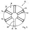
- Fig. 1 schematically shows a sectional view through a permanent magnet motor according to the present invention.
- the motor comprises a stator 10 and a rotor assembly 12 according to the present invention.
- the rotor assembly 12 is mounted on a shaft 14.
- the rotor assembly 12 comprises a rotor body 18, comprising a magnetic core and a yoke, and permanent magnets 20, 22, 24, 26, 28, 30. Magnet poles 32, 34, 36, 38, 40, 42 are formed between the permanent magnets 20 to 30.
- the magnetisation of the core material of the rotor body 18 is indicated by N (north) and S (south) in the drawing.
- the permanent magnets 20 to 30 are embedded in slots (Fig. 2) in the rotor body 18, the slots having end sections 44, 46, 48, 50, 52, 54 of enlarged widths. These end sections 44 to 54 can be formed by recesses or notches provided in the end sections of the slots near the outer periphery of the rotor body 18.
- a permanent magnet motor comprises additional components, such as windings, a housing, electric and electronic control components etc., as shown in Fig. 5.
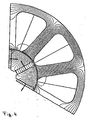
- Fig. 2 shows an enlarged view of the rotor assembly according to the present invention.
- the same components as in Fig. 1 are designated with the same reference numbers.
- the reference numbers of some of the permanent magnets 20 to 30 and poles 32 to 42 are omitted.
- the rotor body 18 forms a magnetic core including a yoke and, accordingly, is made from a material having suitable magnetic properties.
- the shaft 14 can be made from a magnetic or non-magnetic material, as long as magnetic separation between the shaft and the rotor body 18 is ensured.
- the rotor body 18 can be mounted on the shaft 14 via a hub (not shown).
- the magnets 20 to 30 are provided in slots 58 which are formed in the rotor body 18.
- the slots 58 are open at an inner opening 62 of the rotor body 18 and they are closed by relatively thin bridges 64 at the outer periphery of the rotor body 18.
- the magnets 20 to 30 can be inserted into the slots 58 from the inner opening 62 of the rotor body 18 and are securely held therein.
- the bridges 64 at the outer periphery of the rotor body 18 protect the magnets 20 to 30 against any mechanical and electromagnetic damage. As these bridges conduct the significant portion of stray flux, it is important to carefully define the thickness of these bridges 64 to satisfy the requirements regarding both mechanical stability and stray flux.
- the slot 58 has an end section 50 of enlarged widths.
- This end section can be formed by providing notches or recesses in the end section for varying the widths of each slot.
- the permanent magnets 20, 22, 24, 26, 28, 30 are shown to be fully inserted into the end sections 44, 46, 48, 50, 52, 54 in Fig. 1 and 2, an expert will understand that the permanent magnets can extend only partly into said end sections 44, 46, 48, 50, 52, 54 or may stop short of the end sections.
- the shape of the end sections in particular, the widths of the slots at said end sections serves for controlling flux concentration through the pole arc 32 to 42 which is defined between the end sections 44 to 54 of the slots.
- Fig. 3 shows a modification of the rotor assembly according to the present invention.
- the same components are designated by the same reference numbers used in Fig. 2.
- the poles 32 to 42 of the rotor body, between the magnets 20, 22, 24, 26, 28, 30 are provided with a convex shape 70.
- the shape of the rotor body is a further measure to control the distribution of the radial component of the electromagnetic induction in the air-gap. For controlling the electromagnetic induction it is possible to provide convex or concave poles having different shapes.
- Fig. 4 shows a schematic sectional view through a part of the motor of Fig. 1 for illustrating the magnetic flux passing through the magnetic core formed from the rotor body and the stator.
- Fig. 4 shows how the end sections of the slots having enlarged widths influence the radial distribution of the magnetic flux and, in particular, have a flux concentration effect which also helps for reducing the cogging torque.
- An expert will understand that the shape of the end section of the slots can be varied, in particular, it can be made wider or narrower, for adjusting the induction and the cogging torque according to the particular needs of the application.
Landscapes
- Engineering & Computer Science (AREA)
- Power Engineering (AREA)
- Permanent Field Magnets Of Synchronous Machinery (AREA)
- Iron Core Of Rotating Electric Machines (AREA)
- Permanent Magnet Type Synchronous Machine (AREA)
Claims (10)
- Rotor pour une machine électrique, comprenant
un corps (18) de forme généralement cylindrique ayant une ouverture intérieure (62), dans lequel des encoches (58) sont prévues dans le corps (18), les encoches (58) s'étendant à partir de l'ouverture intérieure (62) vers la périphérie extérieure du corps (18) ; des aimants permanents (20-30) sous forme de parallélépipèdes rectangles sont disposés dans lesdites encoches (58) ;dans lequel les encoches (58) comprenant les aimants (20-30) s'étendent approximativement radialement à travers ledit corps et sont fermées par des ponts (64) sur la périphérie extérieure du corps (18) ;
dans lequel au moins une des encoches (58) comprend une section finale (44-54) à proximité de la périphérie extérieure du corps (18) ayant une zone élargie adjacente à un rebord extérieur de l'aimant permanent correspondant (20-30) disposé dans ladite encoche (58) ; et dans lequel ladite section finale (44-54) ayant ladite zone élargie comprend un élément n'ayant aucune propriété magnétique. - Rotor selon la revendication 1 dans lequel les encoches (58) sont fermées auxdites sections finales à proximité de la périphérie extérieure du corps, et les encoches (58) comprennent des cavités créant lesdites zones élargies à proximité de la périphérie extérieure.
- Rotor selon la revendication 1 ou 2 dans lequel les aimants permanents (20-30) se terminent juste avant ladite zone élargie.
- Rotor selon la revendication 1 ou 2 dans lequel les aimants permanents (20-30) s'étendent dans ladite zone élargie.
- Rotor selon l'une quelconque des revendications précédentes dans lequel le corps du rotor (18) comprend un noyau magnétique.
- Rotor selon l'une quelconque des revendications précédentes, dans lequel ladite ouverture intérieure (62) est configurée pour le montage coaxial du corps (18) sur un arbre (14).
- Rotor selon la revendication 6 dans lequel le corps (18) est monté sur l'arbre (14) au moyen d'un moyeu.
- Rotor selon la revendication 7 dans lequel le moyeu est fabriqué dans un matériau non magnétique.
- Rotor selon l'une quelconque des revendications précédentes, dans lequel la périphérie extérieure du corps (18) a une forme convexe ou concave entre deux aimants permanents adjacents.
- Moteur à aimant permanent comprenant un rotor selon l'une des revendications précédentes et un stator (10) coopérant avec ledit rotor.
Priority Applications (4)
| Application Number | Priority Date | Filing Date | Title |
|---|---|---|---|
| EP02025490A EP1420499B1 (fr) | 2002-11-15 | 2002-11-15 | Rotor à aimants permanents encastrés |
| DE60212406T DE60212406T2 (de) | 2002-11-15 | 2002-11-15 | Läufer mit eingebetteten Dauermagneten |
| US10/634,835 US6897590B2 (en) | 2002-11-15 | 2003-08-06 | Rotor assembly for a permanent magnet electrical machine comprising such a rotor assembly |
| JP2003383402A JP2004173491A (ja) | 2002-11-15 | 2003-11-13 | 電気機械用のロータ装置及び永久磁石モータ |
Applications Claiming Priority (1)
| Application Number | Priority Date | Filing Date | Title |
|---|---|---|---|
| EP02025490A EP1420499B1 (fr) | 2002-11-15 | 2002-11-15 | Rotor à aimants permanents encastrés |
Publications (2)
| Publication Number | Publication Date |
|---|---|
| EP1420499A1 EP1420499A1 (fr) | 2004-05-19 |
| EP1420499B1 true EP1420499B1 (fr) | 2006-06-14 |
Family
ID=32116252
Family Applications (1)
| Application Number | Title | Priority Date | Filing Date |
|---|---|---|---|
| EP02025490A Expired - Lifetime EP1420499B1 (fr) | 2002-11-15 | 2002-11-15 | Rotor à aimants permanents encastrés |
Country Status (4)
| Country | Link |
|---|---|
| US (1) | US6897590B2 (fr) |
| EP (1) | EP1420499B1 (fr) |
| JP (1) | JP2004173491A (fr) |
| DE (1) | DE60212406T2 (fr) |
Cited By (1)
| Publication number | Priority date | Publication date | Assignee | Title |
|---|---|---|---|---|
| US9429495B2 (en) | 2004-06-04 | 2016-08-30 | Carl Zeiss Smt Gmbh | System for measuring the image quality of an optical imaging system |
Families Citing this family (36)
| Publication number | Priority date | Publication date | Assignee | Title |
|---|---|---|---|---|
| DE102004017507A1 (de) * | 2004-04-08 | 2005-10-27 | Minebea Co., Ltd. | Rotoranordnung für eine elektrische Maschine |
| JP4574297B2 (ja) * | 2004-09-13 | 2010-11-04 | 日産自動車株式会社 | 回転電機のロータ |
| KR100644836B1 (ko) * | 2004-09-17 | 2006-11-10 | 엘지전자 주식회사 | 자속 집중형 모터 |
| DE102004047311A1 (de) * | 2004-09-29 | 2006-04-13 | Minebea Co., Ltd. | Rotorkörper für einen Rotor einer elektrischen Maschine und Verfahren zur Herstellung eines Rotorkörpers |
| DE102004049072A1 (de) * | 2004-10-08 | 2006-04-13 | Temic Automotive Electric Motors Gmbh | Permanenterregter Motor, insbesonere EC-Motor |
| TW200701595A (en) * | 2005-06-28 | 2007-01-01 | Delta Electronics Inc | Motor rotor |
| EP1746707A1 (fr) | 2005-07-20 | 2007-01-24 | Siemens Aktiengesellschaft | Moteur synchrone à aimants permanents sans balais avec rotor à aimants incorporés et force contre-électromotrice trapézoidale |
| US7772735B2 (en) | 2006-04-19 | 2010-08-10 | Asmo Co., Ltd. | Embedded magnet type rotating electric machine |
| US7821217B2 (en) * | 2006-05-22 | 2010-10-26 | Black & Decker Inc. | Electronically commutated motor and control system employing phase angle control of phase current |
| US7385328B2 (en) * | 2006-05-23 | 2008-06-10 | Reliance Electric Technologies, Llc | Cogging reduction in permanent magnet machines |
| DE102008007335A1 (de) * | 2007-02-28 | 2008-09-11 | Hans Hermann Rottmerhusen | Elektronisch kommutierter Elektromotor |
| KR200462693Y1 (ko) * | 2008-01-31 | 2012-09-26 | 삼성전자주식회사 | 자속 집중형 전동기 |
| US8222787B2 (en) * | 2009-04-01 | 2012-07-17 | General Electric Company | Electric machine |
| FI20090417A (fi) * | 2009-11-10 | 2011-05-11 | Abb Oy | Kestomagneeteilla magnetoitu tahtikone ja menetelmä sen valmistamiseksi ja asentamiseksi |
| KR101566047B1 (ko) * | 2011-03-29 | 2015-11-05 | 한양대학교 산학협력단 | 자속 집중형 영구자석 전동기 |
| JP5429241B2 (ja) * | 2011-08-02 | 2014-02-26 | 株式会社安川電機 | 回転電機 |
| JP5863410B2 (ja) * | 2011-11-16 | 2016-02-16 | 信越化学工業株式会社 | 回転子及びスポーク型ipm永久磁石式回転機 |
| FR2983007B1 (fr) * | 2011-11-18 | 2015-03-06 | Leroy Somer Moteurs | Rotor de machine electrique tournante a aimants permanents. |
| FR2983657B1 (fr) * | 2011-12-01 | 2014-09-05 | Valeo Equip Electr Moteur | Rotor de machine electrique tournante et machine electrique tournante comprenant un tel rotor |
| EP2639934B1 (fr) * | 2012-03-16 | 2015-04-29 | Siemens Aktiengesellschaft | Rotor à excitation permanente, machine électrique dotée d'un tel rotor et procédé de fabrication du rotor |
| KR20140028737A (ko) * | 2012-08-30 | 2014-03-10 | 현대모비스 주식회사 | 고출력 모터용 회전자 |
| CN104937815B (zh) * | 2013-01-24 | 2017-06-13 | 三菱电机株式会社 | 永磁体式旋转电机 |
| JP6117794B2 (ja) | 2013-01-31 | 2017-04-19 | マブチモーター株式会社 | ロータおよびモータ |
| JP2014176147A (ja) * | 2013-03-07 | 2014-09-22 | Mitsubishi Electric Corp | 永久磁石式回転電機 |
| JP5892106B2 (ja) * | 2013-04-15 | 2016-03-23 | 株式会社安川電機 | 回転電機及び回転子の製造方法 |
| CN104682650A (zh) * | 2013-11-28 | 2015-06-03 | 德昌电机(深圳)有限公司 | 电机转子以及具有该电机转子的无刷电机 |
| JP5989878B2 (ja) * | 2015-09-15 | 2016-09-07 | 信越化学工業株式会社 | 回転子及びスポーク型ipm永久磁石式回転機 |
| JP6673707B2 (ja) * | 2016-02-03 | 2020-03-25 | 日本電産サンキョー株式会社 | 埋込磁石型モータ |
| DE102017213653A1 (de) * | 2017-08-07 | 2019-02-07 | Magna powertrain gmbh & co kg | Antriebsvorrichtung |
| CN107222046B (zh) * | 2017-08-09 | 2023-07-07 | 珠海格力节能环保制冷技术研究中心有限公司 | 切向电机及切向电机转子 |
| US10581287B2 (en) * | 2018-01-02 | 2020-03-03 | GM Global Technology Operations LLC | Permanent magnet electric machine with variable magnet orientation |
| CN108808918A (zh) * | 2018-06-11 | 2018-11-13 | 宝龙电子集团有限公司 | 一种驱动马达 |
| JP7308441B2 (ja) * | 2019-02-07 | 2023-07-14 | パナソニックIpマネジメント株式会社 | 電動工具 |
| CN112564343B (zh) * | 2019-07-22 | 2022-08-30 | 北京和山逢泰科技有限公司 | 旋转电机及其转子组件 |
| TWI758983B (zh) * | 2020-12-01 | 2022-03-21 | 天容寶節能科技股份有限公司 | 永磁轉子、相關的永磁電動機以及相關的永磁發電機 |
| EP4293875A1 (fr) * | 2022-06-15 | 2023-12-20 | Vorwerk & Co. Interholding GmbH | Moteur électrique, robot de cuisine et procédé de montage |
Family Cites Families (18)
| Publication number | Priority date | Publication date | Assignee | Title |
|---|---|---|---|---|
| DE2538320B2 (de) * | 1974-08-30 | 1980-01-24 | Inland Motor Division Of Kollmorgen Corp., Radford, Va. (V.St.A.) | Läufer für Gleichstrommotoren mit invertiertem Aufbau und Verfahren zur Herstellung |
| JPS5846859A (ja) | 1981-09-11 | 1983-03-18 | Fanuc Ltd | 同期モ−タ |
| JP3224890B2 (ja) | 1993-02-15 | 2001-11-05 | ファナック株式会社 | 同期電動機のロータ |
| DE4423620A1 (de) * | 1994-07-06 | 1996-01-11 | Philips Patentverwaltung | Mittels Permanentmagneten erregbarer elektrischer Motor, insbesondere Innenläufer- oder Außenläufermotor |
| JPH08331784A (ja) * | 1995-03-24 | 1996-12-13 | Hitachi Metals Ltd | 永久磁石界磁方式回転機 |
| US5811904A (en) * | 1996-03-21 | 1998-09-22 | Hitachi, Ltd. | Permanent magnet dynamo electric machine |
| TW364234B (en) | 1997-04-14 | 1999-07-11 | Sanyo Electric Co | Rotor for an electric motor |
| MY114070A (en) * | 1997-07-22 | 2002-07-31 | Matsushita Electric Ind Co Ltd | A motor using a rotor including an interior permanent magnet |
| JP3906882B2 (ja) | 1997-10-24 | 2007-04-18 | 株式会社富士通ゼネラル | 永久磁石電動機 |
| KR100263445B1 (ko) | 1997-11-13 | 2000-08-01 | 윤종용 | 브러시리스 dc모터용 회전자 |
| US6274960B1 (en) * | 1998-09-29 | 2001-08-14 | Kabushiki Kaisha Toshiba | Reluctance type rotating machine with permanent magnets |
| JP2000152534A (ja) * | 1998-11-16 | 2000-05-30 | Matsushita Electric Ind Co Ltd | 永久磁石電動機 |
| JP2000156947A (ja) * | 1998-11-17 | 2000-06-06 | Yukio Kinoshita | 磁石式電動機及び発電機 |
| US6133663A (en) | 1999-04-01 | 2000-10-17 | A. O. Smith Corporation | Brushless permanent magnet machine |
| JP2001095182A (ja) | 1999-09-20 | 2001-04-06 | Fujitsu General Ltd | 永久磁石電動機 |
| JP2001136690A (ja) * | 1999-11-10 | 2001-05-18 | Isuzu Motors Ltd | 回転機のロータ |
| JP2001314052A (ja) * | 2000-02-25 | 2001-11-09 | Nissan Motor Co Ltd | 同期電動機のロータ構造 |
| JP3513467B2 (ja) * | 2000-06-16 | 2004-03-31 | ファナック株式会社 | 同期電動機のロータ |
-
2002
- 2002-11-15 DE DE60212406T patent/DE60212406T2/de not_active Expired - Lifetime
- 2002-11-15 EP EP02025490A patent/EP1420499B1/fr not_active Expired - Lifetime
-
2003
- 2003-08-06 US US10/634,835 patent/US6897590B2/en not_active Expired - Fee Related
- 2003-11-13 JP JP2003383402A patent/JP2004173491A/ja active Pending
Cited By (1)
| Publication number | Priority date | Publication date | Assignee | Title |
|---|---|---|---|---|
| US9429495B2 (en) | 2004-06-04 | 2016-08-30 | Carl Zeiss Smt Gmbh | System for measuring the image quality of an optical imaging system |
Also Published As
| Publication number | Publication date |
|---|---|
| JP2004173491A (ja) | 2004-06-17 |
| DE60212406D1 (de) | 2006-07-27 |
| US20040095033A1 (en) | 2004-05-20 |
| DE60212406T2 (de) | 2007-02-01 |
| US6897590B2 (en) | 2005-05-24 |
| EP1420499A1 (fr) | 2004-05-19 |
Similar Documents
| Publication | Publication Date | Title |
|---|---|---|
| EP1420499B1 (fr) | Rotor à aimants permanents encastrés | |
| EP1450462B1 (fr) | Rotor et stator de machine électrique avec des pulsations de couple réduites | |
| US6927519B2 (en) | Rotor assembly for an electrical machine and permanent magnet motor comprising such a rotor assembly | |
| EP2617121B1 (fr) | Rotor pour une machine à pôles modulée | |
| US9831726B2 (en) | Electrical machine | |
| US7233090B2 (en) | Electric machine, in particular brushless synchronous motor | |
| US7196446B2 (en) | Rotor for an electric motor | |
| EP1990895B1 (fr) | Géométrie de rotor à aimants permanents à répartition de contraintes pour machines électriques | |
| JP4720982B2 (ja) | アキシャルエアギャップ型電動機 | |
| EP2667483B1 (fr) | Rotor et moteur comprenant un rotor | |
| EP1710891B1 (fr) | Moteur | |
| JP2003324920A (ja) | 高速ロータを有する電気装置 | |
| JP2004328992A (ja) | モータ用ロータ本体、およびモータ | |
| JP2005110485A (ja) | モータ用ロータ本体、およびモータ | |
| CN108462268B (zh) | 旋转电机的转子 | |
| EP0817360A3 (fr) | Moteur pas-à-pas hybride | |
| CN111953098B (zh) | 旋转电机 | |
| JP5672149B2 (ja) | 回転電機用ロータ、および、これを用いた回転電機 | |
| AU2020392823A1 (en) | Rotor for rotating electrical machine | |
| JP5099147B2 (ja) | Ipmモータ用ロータとその製造方法 | |
| CN113646993A (zh) | 马达 | |
| US20240221987A1 (en) | Apparatus for manufacturing rotor | |
| JP2006020442A (ja) | アキシャルギャップ型回転電機の回転子構造 | |
| JP2020156198A (ja) | 回転電機 | |
| CN114915064A (zh) | 转子以及无刷马达 |
Legal Events
| Date | Code | Title | Description |
|---|---|---|---|
| PUAI | Public reference made under article 153(3) epc to a published international application that has entered the european phase |
Free format text: ORIGINAL CODE: 0009012 |
|
| AK | Designated contracting states |
Kind code of ref document: A1 Designated state(s): AT BE BG CH CY CZ DE DK EE ES FI FR GB GR IE IT LI LU MC NL PT SE SK TR |
|
| AX | Request for extension of the european patent |
Extension state: AL LT LV MK RO SI |
|
| 17P | Request for examination filed |
Effective date: 20040730 |
|
| 17Q | First examination report despatched |
Effective date: 20041111 |
|
| AKX | Designation fees paid |
Designated state(s): CH DE FR IT LI |
|
| GRAP | Despatch of communication of intention to grant a patent |
Free format text: ORIGINAL CODE: EPIDOSNIGR1 |
|
| GRAC | Information related to communication of intention to grant a patent modified |
Free format text: ORIGINAL CODE: EPIDOSCIGR1 |
|
| GRAS | Grant fee paid |
Free format text: ORIGINAL CODE: EPIDOSNIGR3 |
|
| GRAA | (expected) grant |
Free format text: ORIGINAL CODE: 0009210 |
|
| AK | Designated contracting states |
Kind code of ref document: B1 Designated state(s): CH DE FR IT LI |
|
| PG25 | Lapsed in a contracting state [announced via postgrant information from national office to epo] |
Ref country code: IT Free format text: LAPSE BECAUSE OF FAILURE TO SUBMIT A TRANSLATION OF THE DESCRIPTION OR TO PAY THE FEE WITHIN THE PRESCRIBED TIME-LIMIT;WARNING: LAPSES OF ITALIAN PATENTS WITH EFFECTIVE DATE BEFORE 2007 MAY HAVE OCCURRED AT ANY TIME BEFORE 2007. THE CORRECT EFFECTIVE DATE MAY BE DIFFERENT FROM THE ONE RECORDED. Effective date: 20060614 Ref country code: CH Free format text: LAPSE BECAUSE OF FAILURE TO SUBMIT A TRANSLATION OF THE DESCRIPTION OR TO PAY THE FEE WITHIN THE PRESCRIBED TIME-LIMIT Effective date: 20060614 Ref country code: LI Free format text: LAPSE BECAUSE OF FAILURE TO SUBMIT A TRANSLATION OF THE DESCRIPTION OR TO PAY THE FEE WITHIN THE PRESCRIBED TIME-LIMIT Effective date: 20060614 |
|
| REG | Reference to a national code |
Ref country code: CH Ref legal event code: EP |
|
| REF | Corresponds to: |
Ref document number: 60212406 Country of ref document: DE Date of ref document: 20060727 Kind code of ref document: P |
|
| PGFP | Annual fee paid to national office [announced via postgrant information from national office to epo] |
Ref country code: FR Payment date: 20061108 Year of fee payment: 5 |
|
| PGFP | Annual fee paid to national office [announced via postgrant information from national office to epo] |
Ref country code: IT Payment date: 20061130 Year of fee payment: 5 |
|
| ET | Fr: translation filed | ||
| REG | Reference to a national code |
Ref country code: CH Ref legal event code: PL |
|
| PLBE | No opposition filed within time limit |
Free format text: ORIGINAL CODE: 0009261 |
|
| STAA | Information on the status of an ep patent application or granted ep patent |
Free format text: STATUS: NO OPPOSITION FILED WITHIN TIME LIMIT |
|
| 26N | No opposition filed |
Effective date: 20070315 |
|
| REG | Reference to a national code |
Ref country code: FR Ref legal event code: ST Effective date: 20080930 |
|
| PG25 | Lapsed in a contracting state [announced via postgrant information from national office to epo] |
Ref country code: FR Free format text: LAPSE BECAUSE OF NON-PAYMENT OF DUE FEES Effective date: 20071130 |
|
| PG25 | Lapsed in a contracting state [announced via postgrant information from national office to epo] |
Ref country code: IT Free format text: LAPSE BECAUSE OF NON-PAYMENT OF DUE FEES Effective date: 20071115 |
|
| REG | Reference to a national code |
Ref country code: DE Ref legal event code: R082 Ref document number: 60212406 Country of ref document: DE Representative=s name: BOEHMERT & BOEHMERT ANWALTSPARTNERSCHAFT MBB -, DE Ref country code: DE Ref legal event code: R081 Ref document number: 60212406 Country of ref document: DE Owner name: MINEBEA MITSUMI INC., JP Free format text: FORMER OWNER: MINEBEA CO., LTD., NAGANO, JP |
|
| PGFP | Annual fee paid to national office [announced via postgrant information from national office to epo] |
Ref country code: DE Payment date: 20211130 Year of fee payment: 20 |
|
| REG | Reference to a national code |
Ref country code: DE Ref legal event code: R071 Ref document number: 60212406 Country of ref document: DE |