EP1420499B1 - Rotor with embedded permanent magnets - Google Patents
Rotor with embedded permanent magnets Download PDFInfo
- Publication number
- EP1420499B1 EP1420499B1 EP02025490A EP02025490A EP1420499B1 EP 1420499 B1 EP1420499 B1 EP 1420499B1 EP 02025490 A EP02025490 A EP 02025490A EP 02025490 A EP02025490 A EP 02025490A EP 1420499 B1 EP1420499 B1 EP 1420499B1
- Authority
- EP
- European Patent Office
- Prior art keywords
- rotor assembly
- slots
- rotor
- assembly according
- permanent magnets
- Prior art date
- Legal status (The legal status is an assumption and is not a legal conclusion. Google has not performed a legal analysis and makes no representation as to the accuracy of the status listed.)
- Expired - Lifetime
Links
Images


Classifications
-
- H—ELECTRICITY
- H02—GENERATION; CONVERSION OR DISTRIBUTION OF ELECTRIC POWER
- H02K—DYNAMO-ELECTRIC MACHINES
- H02K1/00—Details of the magnetic circuit
- H02K1/06—Details of the magnetic circuit characterised by the shape, form or construction
- H02K1/22—Rotating parts of the magnetic circuit
- H02K1/27—Rotor cores with permanent magnets
- H02K1/2706—Inner rotors
- H02K1/272—Inner rotors the magnetisation axis of the magnets being perpendicular to the rotor axis
- H02K1/274—Inner rotors the magnetisation axis of the magnets being perpendicular to the rotor axis the rotor consisting of two or more circumferentially positioned magnets
- H02K1/2753—Inner rotors the magnetisation axis of the magnets being perpendicular to the rotor axis the rotor consisting of two or more circumferentially positioned magnets the rotor consisting of magnets or groups of magnets arranged with alternating polarity
- H02K1/276—Magnets embedded in the magnetic core, e.g. interior permanent magnets [IPM]
- H02K1/2766—Magnets embedded in the magnetic core, e.g. interior permanent magnets [IPM] having a flux concentration effect
- H02K1/2773—Magnets embedded in the magnetic core, e.g. interior permanent magnets [IPM] having a flux concentration effect consisting of tangentially magnetized radial magnets
Definitions
- the present invention relates to a rotor assembly for a permanent magnet (P.M).electrical machine or a D.C. motor comprising such a rotor assembly.
- the invention relates to the field of permanent magnet motors and brushless D.C. motors comprising permanent magnets which can be configured to include an inner rotor surrounded by a stator ( réellehomrmotor) or an outer rotor configuration (Außenlaufermotor).
- Electrical machines having an interior rotor include a rotor assembly which is mounted on the rotor shaft and one or more permanent magnets as well as a stator assembly, such as a stator laminated from a number of metal sheets, comprising windings. The rotor assembly is coaxially inserted into the stator assembly. In electrical machines having outer rotors, the rotor assembly surrounds the stator.
- Fig. 5 schematically shows the general design of an electrical machine, comprising a housing 114, in which are included the stator assembly 118, the rotor assembly 116 as well as bearings 126, 128 for rotatably supporting the rotor assembly.
- the stator assembly 118 comprises sheet metals 155 and windings 160 and defines an interior cavity into which the rotor assembly 116 can be inserted.
- the rotor assembly 116 includes the shaft 110, a yoke 112 and permanent magnets 122.
- the bearings 126, 128 for the rotor assembly can be integrated into a flange 124 of the motor housing 114.
- the present invention relates to a rotor assembly for an electrical machine , comprising a body of generally cylindrical shape having an inner opening for coaxially mounting the body on a shaft, and permanent magnets embedded in said body.
- Rotors including embedded magnets have been generally known and described in the art.
- a rotor configuration having a multi-pole "spoke” design with radially extending embedded magnets, enclosed by a retaining ring is shown e.g. in "Design of Brushless Permanent-Magnet Motors” J.R. Hendershot Jr. and TJE Miller, Magna Physics Publishing and Clarendon Press, Oxford, 1994.
- the rotor body in which the magnets are embedded has the function of a yoke.
- EP 0 641 059 B and EP 0 691 727 B1 show a plurality of magnets which are inserted into slots which are formed in the outer rotor surface. With the design disclosed in these references, stray flux is created which passes through the rotor back-iron close to the shaft. Accordingly, magnet energy dissipated in this area can't be used efficiently.
- Document DE 101 00 718 A1 discloses a similar design wherein the permanent magnets are inserted into slots in the rotor body which are closed at the outer rotor surface. Thereby, the rotor is divided into sectors which need to be mounted on a frame.
- WO 00/57537 describes a multipole, permanent-magnet rotor for a rotating electrical machine, manufactured with embedded magnets in a so-called "flux-concentrating style".
- permanent magnets are designed as flat cubes which are arranged in a direction radial to the rotor axis in groove-like gaps between yoke sections fixed in the rotor body.
- this document proposes to divide a yoke into two adjacent half-yokes of two poles, wherein magnets are arranged there between to form a pole element which can be fixed independently on the rotor body.
- EP 0 872 944 A1 shows another design of a rotor having embedded permanent magnets wherein the magnets are arranged in a radial direction or parallel to a radial direction of the rotor body.
- the rotor is made of a ferromagnetic material body defining a plurality of radially by extending slots in which are engaged the permanent magnets so as to provide the desired numbers of poles for the rotor.
- the slots for receiving the permanent magnets are designed with a bridge at the outer periphery of the rotor body and an opening at the inner diameter of the rotor body so that the permanent magnets can be inserted and held in said slots. Trapezoidal elements of the rotor body which are separated by the radially extending slots will form the poles of the rotor.
- EP 1 100 175 discloses a rotor assembly for an electric machine including a body of generally cylindrical shape having an inner opening, wherein slots are provided in the body, the slot extending radially from the inner opening towards the outer periphery of the body. After stacking the rotor laminations, magnetic material is filled into the slots, intermediate spaces are filled by non-magnetic material and the magnetic material is magnetized. Subsequently, the rotor is machined to cut away the outer peripheral portions so that the slots including the magnetic and non-magnetic material are open towards the outside.
- EP 1 003 267 discloses a rotor body in which magnets having different strength are inserted into radial slots to change the magnetic distribution of the air gap and the strength of the magnetic force generated by the magnets.
- the preferred application of the rotor assembly according to the present invention is in a brushless D.C. motor or permanent magnet synchronous motor.
- Such motors can be used in a wide range of applications such as spindle motors for disc drives, electrical motor power assisted systems in automobiles, e.g. steering and braking systems, power tools and many other applications.
- a rotor assembly for an electrical machine comprising a body of generally cylindrical shape having an inner opening.
- slots are provided which extend from the inner opening towards the outer periphery of the body, permanent magnets are disposed in said slots.
- at least one of the slots comprises an end section near the outer periphery of the body having an area of enlarged width. The area of enlarged width at the outer ends of the slots improve the flux concentration in the air gap between the stator and the rotor.
- the end sections of the slots, near the outer periphery of the body, are closed to the outside and include recesses or notches creating said area of enlarged widths of the slots.
- the permanent magnets which are inserted into said slots do not extend into said area of enlarged widths.
- the permanent magnets extend partly or fully into said area of enlarged widths. That part of the end section which is not occupied by the permanent magnets can be filled with air or another medium having no magnetic properties.
- the permanent magnets do not extend all the way into the area of enlarged width at the outer end of the slots. This results in a configuration where an "empty" end of the slots close to the outer periphery of the rotor assembly is created which has a positive influence on the cogging torque.
- the present invention allows four parameters for motor tuning.
- the motor can be tuned as a function of the height of each magnet, the width of each magnet, the shape and size of a recess in the end section of the slot containing the permanent magnet, and the length of the permanent magnet extending into said end section. Therefore, it is easier to influence the flux concentration and distribution of the electromagnetic induction in the air gap as with the arrangements according to the prior art.
- the slots are closed by bridges which protect the magnets against possible mechanical and electromagnetic damage and which connect the poles on the two sides of each magnet.
- these bridges conduct a large portion of stray flux. Therefore, the thickness of the bridges has to be designed carefully to satisfy both requirements regarding protection of the permanent magnets and reduction of stray flux.
- the present invention there is no (metal) retaining tube necessary for protecting the permanent magnets and holding the permanent magnets in place. Accordingly, the size of the air-gap can be reduced and the energy from the magnet can be transferred more efficiently to the stator so that there is less energy loss. As a consequence, the volume of magnetic material can be reduced when compared with a surface magnet designed under equal conditions otherwise. Accordingly, with the proposed arrangement of the magnet sections in slots which are closed at the outer periphery of the body the overall efficiency of the motor can be increased.
- the present invention provides for a rotor assembly wherein the rotor body forms a magnetic core, with magnets embedded therein.
- the inner opening of the rotor body is configured for mounting the rotor body on a shaft.
- the body is mounted on the shaft via a hub.
- the hub should be made of a non-magnetic material.
- the rotor body is configured to surround a stator of the electrical machine, with an air-gap being formed between the rotor and the stator.
- the outer periphery of the body has a convex or concave shape between two adjacent permanent magnets. This serves as an additional measure to control the distribution of the radial component of the electromagnetic induction.
- the magnetic poles formed between two adjacent permanent magnets can have different shapes to control the distribution of the electromagnetic induction and in particular, different convex or concave shapes.
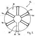
- Fig. 1 schematically shows a sectional view through a permanent magnet motor according to the present invention.
- the motor comprises a stator 10 and a rotor assembly 12 according to the present invention.
- the rotor assembly 12 is mounted on a shaft 14.
- the rotor assembly 12 comprises a rotor body 18, comprising a magnetic core and a yoke, and permanent magnets 20, 22, 24, 26, 28, 30. Magnet poles 32, 34, 36, 38, 40, 42 are formed between the permanent magnets 20 to 30.
- the magnetisation of the core material of the rotor body 18 is indicated by N (north) and S (south) in the drawing.
- the permanent magnets 20 to 30 are embedded in slots (Fig. 2) in the rotor body 18, the slots having end sections 44, 46, 48, 50, 52, 54 of enlarged widths. These end sections 44 to 54 can be formed by recesses or notches provided in the end sections of the slots near the outer periphery of the rotor body 18.
- a permanent magnet motor comprises additional components, such as windings, a housing, electric and electronic control components etc., as shown in Fig. 5.
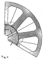
- Fig. 2 shows an enlarged view of the rotor assembly according to the present invention.
- the same components as in Fig. 1 are designated with the same reference numbers.
- the reference numbers of some of the permanent magnets 20 to 30 and poles 32 to 42 are omitted.
- the rotor body 18 forms a magnetic core including a yoke and, accordingly, is made from a material having suitable magnetic properties.
- the shaft 14 can be made from a magnetic or non-magnetic material, as long as magnetic separation between the shaft and the rotor body 18 is ensured.
- the rotor body 18 can be mounted on the shaft 14 via a hub (not shown).
- the magnets 20 to 30 are provided in slots 58 which are formed in the rotor body 18.
- the slots 58 are open at an inner opening 62 of the rotor body 18 and they are closed by relatively thin bridges 64 at the outer periphery of the rotor body 18.
- the magnets 20 to 30 can be inserted into the slots 58 from the inner opening 62 of the rotor body 18 and are securely held therein.
- the bridges 64 at the outer periphery of the rotor body 18 protect the magnets 20 to 30 against any mechanical and electromagnetic damage. As these bridges conduct the significant portion of stray flux, it is important to carefully define the thickness of these bridges 64 to satisfy the requirements regarding both mechanical stability and stray flux.
- the slot 58 has an end section 50 of enlarged widths.
- This end section can be formed by providing notches or recesses in the end section for varying the widths of each slot.
- the permanent magnets 20, 22, 24, 26, 28, 30 are shown to be fully inserted into the end sections 44, 46, 48, 50, 52, 54 in Fig. 1 and 2, an expert will understand that the permanent magnets can extend only partly into said end sections 44, 46, 48, 50, 52, 54 or may stop short of the end sections.
- the shape of the end sections in particular, the widths of the slots at said end sections serves for controlling flux concentration through the pole arc 32 to 42 which is defined between the end sections 44 to 54 of the slots.
- Fig. 3 shows a modification of the rotor assembly according to the present invention.
- the same components are designated by the same reference numbers used in Fig. 2.
- the poles 32 to 42 of the rotor body, between the magnets 20, 22, 24, 26, 28, 30 are provided with a convex shape 70.
- the shape of the rotor body is a further measure to control the distribution of the radial component of the electromagnetic induction in the air-gap. For controlling the electromagnetic induction it is possible to provide convex or concave poles having different shapes.
- Fig. 4 shows a schematic sectional view through a part of the motor of Fig. 1 for illustrating the magnetic flux passing through the magnetic core formed from the rotor body and the stator.
- Fig. 4 shows how the end sections of the slots having enlarged widths influence the radial distribution of the magnetic flux and, in particular, have a flux concentration effect which also helps for reducing the cogging torque.
- An expert will understand that the shape of the end section of the slots can be varied, in particular, it can be made wider or narrower, for adjusting the induction and the cogging torque according to the particular needs of the application.
Landscapes
- Engineering & Computer Science (AREA)
- Power Engineering (AREA)
- Permanent Field Magnets Of Synchronous Machinery (AREA)
- Iron Core Of Rotating Electric Machines (AREA)
- Permanent Magnet Type Synchronous Machine (AREA)
Description
- The present invention relates to a rotor assembly for a permanent magnet (P.M).electrical machine or a D.C. motor comprising such a rotor assembly. In general, the invention relates to the field of permanent magnet motors and brushless D.C. motors comprising permanent magnets which can be configured to include an inner rotor surrounded by a stator (Innenläufermotor) or an outer rotor configuration (Außenlaufermotor). Electrical machines having an interior rotor include a rotor assembly which is mounted on the rotor shaft and one or more permanent magnets as well as a stator assembly, such as a stator laminated from a number of metal sheets, comprising windings. The rotor assembly is coaxially inserted into the stator assembly. In electrical machines having outer rotors, the rotor assembly surrounds the stator.
- Fig. 5 schematically shows the general design of an electrical machine, comprising a
housing 114, in which are included thestator assembly 118, therotor assembly 116 as well asbearings stator assembly 118 comprisessheet metals 155 andwindings 160 and defines an interior cavity into which therotor assembly 116 can be inserted. Therotor assembly 116 includes theshaft 110, ayoke 112 andpermanent magnets 122. Thebearings flange 124 of themotor housing 114. - More particularly, the present invention relates to a rotor assembly for an electrical machine , comprising a body of generally cylindrical shape having an inner opening for coaxially mounting the body on a shaft, and permanent magnets embedded in said body.
- Rotors including embedded magnets have been generally known and described in the art. A rotor configuration having a multi-pole "spoke" design with radially extending embedded magnets, enclosed by a retaining ring is shown e.g. in "Design of Brushless Permanent-Magnet Motors" J.R. Hendershot Jr. and TJE Miller, Magna Physics Publishing and Clarendon Press, Oxford, 1994. As shown therein, it is known to have a rotor body with embedded, radially extending magnets which are protected by a ring or tube surrounding the rotor body. The rotor body in which the magnets are embedded has the function of a yoke.
- A common form of buried magnets is shown in EP 0 641 059 B and EP 0 691 727 B1. These references show a plurality of magnets which are inserted into slots which are formed in the outer rotor surface. With the design disclosed in these references, stray flux is created which passes through the rotor back-iron close to the shaft. Accordingly, magnet energy dissipated in this area can't be used efficiently. Document DE 101 00 718 A1 discloses a similar design wherein the permanent magnets are inserted into slots in the rotor body which are closed at the outer rotor surface. Thereby, the rotor is divided into sectors which need to be mounted on a frame.
- WO 00/57537 describes a multipole, permanent-magnet rotor for a rotating electrical machine, manufactured with embedded magnets in a so-called "flux-concentrating style". In the rotor configuration shown in this reference permanent magnets are designed as flat cubes which are arranged in a direction radial to the rotor axis in groove-like gaps between yoke sections fixed in the rotor body. For easily mounting the magnets this document proposes to divide a yoke into two adjacent half-yokes of two poles, wherein magnets are arranged there between to form a pole element which can be fixed independently on the rotor body.
- EP 0 872 944 A1 shows another design of a rotor having embedded permanent magnets wherein the magnets are arranged in a radial direction or parallel to a radial direction of the rotor body.
- A similar design is shown in EP 0 803 962 B1. The rotor is made of a ferromagnetic material body defining a plurality of radially by extending slots in which are engaged the permanent magnets so as to provide the desired numbers of poles for the rotor. The slots for receiving the permanent magnets are designed with a bridge at the outer periphery of the rotor body and an opening at the inner diameter of the rotor body so that the permanent magnets can be inserted and held in said slots. Trapezoidal elements of the rotor body which are separated by the radially extending slots will form the poles of the rotor.
- Further patent documents showing a rotor having embedded magnets are GB 1,177,247, EP 0 955 714 A2 and U.S. 2002/0067096 A1.
- EP 1 100 175 discloses a rotor assembly for an electric machine including a body of generally cylindrical shape having an inner opening, wherein slots are provided in the body, the slot extending radially from the inner opening towards the outer periphery of the body. After stacking the rotor laminations, magnetic material is filled into the slots, intermediate spaces are filled by non-magnetic material and the magnetic material is magnetized. Subsequently, the rotor is machined to cut away the outer peripheral portions so that the slots including the magnetic and non-magnetic material are open towards the outside.
- EP 1 003 267 discloses a rotor body in which magnets having different strength are inserted into radial slots to change the magnetic distribution of the air gap and the strength of the magnetic force generated by the magnets.
- The preferred application of the rotor assembly according to the present invention is in a brushless D.C. motor or permanent magnet synchronous motor. Such motors can be used in a wide range of applications such as spindle motors for disc drives, electrical motor power assisted systems in automobiles, e.g. steering and braking systems, power tools and many other applications.
- With the radial arrangement of the permanent magnets, as shown and described in the prior art, a problem may arise in that the regular arrangement of the permanent magnets produces a cogging torque effect which is disadvantageous in the operation of the permanent magnet motor. In a rotor assembly having surface-magnets, it is known to provide a skewed magnet arrangement to avoid abrupt switching between phases and thus to reduce a cogging torque, as disclosed e.g. in the above mentioned reference of Hendershot and Miller. Skewed magnetization of the rotor poles, however, creates an axial component of the magnetic force and thus a loss of torque. Further , the problem of the cogging torque produced during operation of the permanent magnet motor has not yet been solved satisfactorily for rotors having embedded magnets of the type described above. .
- It is therefore an object of the present invention to provide a rotor assembly having embedded magnets which can improve the efficiency of the electrical machine and, in particular, eliminate or reduce the cogging torque.
- This object is solved by a rotor assembly comprising the features of claim 1.
- According to the present invention a rotor assembly for an electrical machine is provided, comprising a body of generally cylindrical shape having an inner opening. In the rotor body slots are provided which extend from the inner opening towards the outer periphery of the body, permanent magnets are disposed in said slots. According to the present invention, at least one of the slots comprises an end section near the outer periphery of the body having an area of enlarged width. The area of enlarged width at the outer ends of the slots improve the flux concentration in the air gap between the stator and the rotor.
- Preferably, the end sections of the slots, near the outer periphery of the body, are closed to the outside and include recesses or notches creating said area of enlarged widths of the slots. In a preferred embodiment, the permanent magnets which are inserted into said slots do not extend into said area of enlarged widths. In another embodiment the permanent magnets extend partly or fully into said area of enlarged widths. That part of the end section which is not occupied by the permanent magnets can be filled with air or another medium having no magnetic properties. To reduce the cogging torque it is preferred that the permanent magnets do not extend all the way into the area of enlarged width at the outer end of the slots. This results in a configuration where an "empty" end of the slots close to the outer periphery of the rotor assembly is created which has a positive influence on the cogging torque.
- By providing an end section of the slots, near the outer periphery of the body, which has enlarged width, in general, it is possible to control the flux concentration through the rotor assembly and the stator and, more particularly, to reduce the cogging torque. The operation of the motor thus can be tuned by choosing an appropriate shape of the end section and controlling the magnet position within the slot.
- While the prior art arrangement of embedded magnets provided for only two degrees of freedom for controlling motor parameters, such as the radial distribution of the electromagnetic induction in the air-gap and flux concentration, namely the widths of each magnet and the height of each magnet, the present invention allows four parameters for motor tuning. According to the present invention, the motor can be tuned as a function of the height of each magnet, the width of each magnet, the shape and size of a recess in the end section of the slot containing the permanent magnet, and the length of the permanent magnet extending into said end section. Therefore, it is easier to influence the flux concentration and distribution of the electromagnetic induction in the air gap as with the arrangements according to the prior art. By optimising the arrangement of the magnet sections and the shape of the slot it is possible to reduce the cogging torque without the necessity of any skewing technique which has been used in the prior art. In particular, by forming the end section of the slot with a wider opening, flux can be concentrated through smaller pole areas to change the flux distribution in the air gap and in particular to reduce the cogging torque. Choosing a slot having a narrow end section will lead to higher induction. The cogging torque can be further controlled by varying the position of the permanent magnet in the slot. In particular, a smaller cogging torque, but also a smaller induction, is achieved when the permanent magnet does not extend into the end section.
- At the outer periphery of the rotor body, the slots are closed by bridges which protect the magnets against possible mechanical and electromagnetic damage and which connect the poles on the two sides of each magnet. However, these bridges conduct a large portion of stray flux. Therefore, the thickness of the bridges has to be designed carefully to satisfy both requirements regarding protection of the permanent magnets and reduction of stray flux.
- According to the present invention, there is no (metal) retaining tube necessary for protecting the permanent magnets and holding the permanent magnets in place. Accordingly, the size of the air-gap can be reduced and the energy from the magnet can be transferred more efficiently to the stator so that there is less energy loss. As a consequence, the volume of magnetic material can be reduced when compared with a surface magnet designed under equal conditions otherwise. Accordingly, with the proposed arrangement of the magnet sections in slots which are closed at the outer periphery of the body the overall efficiency of the motor can be increased.
- The present invention provides for a rotor assembly wherein the rotor body forms a magnetic core, with magnets embedded therein. Preferably, the inner opening of the rotor body is configured for mounting the rotor body on a shaft. In particular the body is mounted on the shaft via a hub. The hub should be made of a non-magnetic material.
- In an alternative embodiment, the rotor body is configured to surround a stator of the electrical machine, with an air-gap being formed between the rotor and the stator.
- In one particular embodiment of the invention, the outer periphery of the body has a convex or concave shape between two adjacent permanent magnets. This serves as an additional measure to control the distribution of the radial component of the electromagnetic induction. In general, the magnetic poles formed between two adjacent permanent magnets can have different shapes to control the distribution of the electromagnetic induction and in particular, different convex or concave shapes.
- In the following, the invention is described by way of preferred embodiments of the invention with reference to the drawings.
- Fig. 1
- shows a schematic sectional view through a motor comprising a stator and a rotor assembly according to the present invention;
- Fig. 2
- shows a schematic sectional view through a rotor assembly according to the present invention;
- Fig. 3
- shows a schematic sectional view through a rotor assembly according to a further embodiment of the present invention;
- Fig. 4
- shows a schematic sectional view through part of the motor of Fig. 1 wherein the magnetic flux is indicated;
- Fig. 5
- shows a schematic sectional view in a longitudinal direction through a permanent magnet motor according to the prior art.
- Fig. 1 schematically shows a sectional view through a permanent magnet motor according to the present invention. The motor comprises a
stator 10 and arotor assembly 12 according to the present invention. Therotor assembly 12 is mounted on ashaft 14. Therotor assembly 12 comprises a rotor body 18, comprising a magnetic core and a yoke, andpermanent magnets Magnet poles permanent magnets 20 to 30. The magnetisation of the core material of the rotor body 18 is indicated by N (north) and S (south) in the drawing. - The
permanent magnets 20 to 30 are embedded in slots (Fig. 2) in the rotor body 18, the slots havingend sections end sections 44 to 54 can be formed by recesses or notches provided in the end sections of the slots near the outer periphery of the rotor body 18. - Further, an
air gap 56 is provided between thestator 10 and therotor assembly 12, An expert will understand that a permanent magnet motor comprises additional components, such as windings, a housing, electric and electronic control components etc., as shown in Fig. 5. - The invention is described in further detail with reference to Fig. 2 which shows an enlarged view of the rotor assembly according to the present invention. The same components as in Fig. 1 are designated with the same reference numbers. For clarity reasons, the reference numbers of some of the
permanent magnets 20 to 30 andpoles 32 to 42 are omitted. - The rotor body 18 forms a magnetic core including a yoke and, accordingly, is made from a material having suitable magnetic properties. The
shaft 14 can be made from a magnetic or non-magnetic material, as long as magnetic separation between the shaft and the rotor body 18 is ensured. The rotor body 18 can be mounted on theshaft 14 via a hub (not shown). - The
magnets 20 to 30 are provided inslots 58 which are formed in the rotor body 18. Theslots 58 are open at an inner opening 62 of the rotor body 18 and they are closed by relativelythin bridges 64 at the outer periphery of the rotor body 18. Themagnets 20 to 30 can be inserted into theslots 58 from the inner opening 62 of the rotor body 18 and are securely held therein. Thebridges 64 at the outer periphery of the rotor body 18 protect themagnets 20 to 30 against any mechanical and electromagnetic damage. As these bridges conduct the significant portion of stray flux, it is important to carefully define the thickness of thesebridges 64 to satisfy the requirements regarding both mechanical stability and stray flux. - As shown in Fig. 2, the
slot 58 has anend section 50 of enlarged widths. This end section can be formed by providing notches or recesses in the end section for varying the widths of each slot. While thepermanent magnets end sections end sections - The shape of the end sections, in particular, the widths of the slots at said end sections serves for controlling flux concentration through the
pole arc 32 to 42 which is defined between theend sections 44 to 54 of the slots. The wider the end sections are, the smaller is the pole arc between these end sections. Thus, by selecting the shape of the end sections of the slots, the flux distribution in the magnet core and the air-gap can be controlled. Further, by adjusting the length of eachmagnet 20 to 30 to fully or partly extend into theend sections 44 to 54 or to stop short of said end sections, it is possible to control the induction and the cogging torque of the permanent magnet motor. - Fig. 3 shows a modification of the rotor assembly according to the present invention. The same components are designated by the same reference numbers used in Fig. 2.
- The difference between the embodiments of Fig. 2 and 3 is that the
poles 32 to 42 of the rotor body, between themagnets - Fig. 4 shows a schematic sectional view through a part of the motor of Fig. 1 for illustrating the magnetic flux passing through the magnetic core formed from the rotor body and the stator. Fig. 4 shows how the end sections of the slots having enlarged widths influence the radial distribution of the magnetic flux and, in particular, have a flux concentration effect which also helps for reducing the cogging torque. An expert will understand that the shape of the end section of the slots can be varied, in particular, it can be made wider or narrower, for adjusting the induction and the cogging torque according to the particular needs of the application.
- The features disclosed in the above specification, the claims and the drawings can be relevant for implementing the various embodiments of the present invention when taken alone or in any combination thereof.
-
- 10
- Stator
- 12
- Rotor assembly
- 14
- Shaft
- 18
- Rotor body
- 20, 22, 24, 26, 28, 30
- Magnets
- 32, 34, 36, 38, 40, 42
- Magnet poles
- 44, 46, 48, 50, 52, 54
- End sections
- 56
- Air gap
- 58
- Slots
- 62
- Inner opening
- 64
- Bridges
- 70
- Convex Shape
- 110
- Shaft
- 112
- Yoke
- 114
- Housing
- 116
- Rotor assembly
- 118
- Stator assembly
- 122
- Permanent magnets
- 124
- Flange
- 126, 128
- Bearing
- 155
- Sheet metals
- 160
- Windings
Claims (10)
- Rotor assembly for an electrical machine, including
a body (18) of generally cylindrical shape having an inner opening (62),
wherein slots (58) are provided in the body (18), the slots (58) extending from the inner opening (62) towards the outer pheriphery of the body (18);
permanent magnets (20-30) in the form of rectangular parallelepipeds disposed in said slots (58);
wherein the slots (58) including the magnets (20-30) extend approximately radially through said body and are closed by bridges (64) at the outer periphery of the body (18);
wherein at least one of the slots (58) comprises an end section (44-54) near the outer pheriphery of the body (18) having an area of enlarged width adjacent an outer edge of the corresponding permanent magnet (20-30) disposed in said slot (58); and
wherein said end section (44-54) having said area of enlarged width includes a medium having no magnetic properties. - Rotor assembly according to claim 1 wherein the slots (58) are closed at said end sections near the outer periphery of the body, and the slots (58) include recesses creating said areas of enlarged width near the outer periphery.
- Rotor assembly according to claim 1 or 2 wherein the permanent magnets (20-30) terminate short of said area of enlarged width.
- Rotor assembly according to claim 1 or 2 wherein the permanent magnets (20-30) extend into said area of enlarged width.
- Rotor assembly according to one of the preceding claims wherein the rotor body (18) comprises a magnetic core.
- Rotor assembly according to one of the preceding claims, wherein said inner opening (62) is configured for coaxially mounting the body (18) on a shaft (14).
- Rotor assembly according to claim 6 wherein the body (18) is mounted on the shaft (14) via a hub.
- Rotor assembly according to claim 7 wherein the hub is of a non-magnetic material.
- Rotor assembly according to one of the preceding claims wherein the outer periphery of the body (18) has a convex or concave shape between two adjacent permanent magnets.
- Permanent magnet motor comprising a rotor assembly according to one of the preceding claims and a stator (10) cooperating with said rotor assembly.
Priority Applications (4)
| Application Number | Priority Date | Filing Date | Title |
|---|---|---|---|
| DE60212406T DE60212406T2 (en) | 2002-11-15 | 2002-11-15 | Runners with embedded permanent magnets |
| EP02025490A EP1420499B1 (en) | 2002-11-15 | 2002-11-15 | Rotor with embedded permanent magnets |
| US10/634,835 US6897590B2 (en) | 2002-11-15 | 2003-08-06 | Rotor assembly for a permanent magnet electrical machine comprising such a rotor assembly |
| JP2003383402A JP2004173491A (en) | 2002-11-15 | 2003-11-13 | Rotor device for electric machine, and permanent magnet motor |
Applications Claiming Priority (1)
| Application Number | Priority Date | Filing Date | Title |
|---|---|---|---|
| EP02025490A EP1420499B1 (en) | 2002-11-15 | 2002-11-15 | Rotor with embedded permanent magnets |
Publications (2)
| Publication Number | Publication Date |
|---|---|
| EP1420499A1 EP1420499A1 (en) | 2004-05-19 |
| EP1420499B1 true EP1420499B1 (en) | 2006-06-14 |
Family
ID=32116252
Family Applications (1)
| Application Number | Title | Priority Date | Filing Date |
|---|---|---|---|
| EP02025490A Expired - Lifetime EP1420499B1 (en) | 2002-11-15 | 2002-11-15 | Rotor with embedded permanent magnets |
Country Status (4)
| Country | Link |
|---|---|
| US (1) | US6897590B2 (en) |
| EP (1) | EP1420499B1 (en) |
| JP (1) | JP2004173491A (en) |
| DE (1) | DE60212406T2 (en) |
Cited By (1)
| Publication number | Priority date | Publication date | Assignee | Title |
|---|---|---|---|---|
| US9429495B2 (en) | 2004-06-04 | 2016-08-30 | Carl Zeiss Smt Gmbh | System for measuring the image quality of an optical imaging system |
Families Citing this family (36)
| Publication number | Priority date | Publication date | Assignee | Title |
|---|---|---|---|---|
| DE102004017507A1 (en) * | 2004-04-08 | 2005-10-27 | Minebea Co., Ltd. | Rotor arrangement for an electric machine |
| JP4574297B2 (en) * | 2004-09-13 | 2010-11-04 | 日産自動車株式会社 | Rotating electrical machine rotor |
| KR100644836B1 (en) * | 2004-09-17 | 2006-11-10 | 엘지전자 주식회사 | Flux concentration type motor |
| DE102004047311A1 (en) * | 2004-09-29 | 2006-04-13 | Minebea Co., Ltd. | Rotor body for a rotor of an electric machine and method for producing a rotor body |
| DE102004049072A1 (en) * | 2004-10-08 | 2006-04-13 | Temic Automotive Electric Motors Gmbh | Permanently excited motor especially electronically commutated motor has pole teeth connected by bridges around the rotor and permanent magnets held in channels |
| TW200701595A (en) * | 2005-06-28 | 2007-01-01 | Delta Electronics Inc | Motor rotor |
| EP1746707A1 (en) * | 2005-07-20 | 2007-01-24 | Siemens Aktiengesellschaft | Brushless synchronous machine with permanent magnet excitation having embedded magnets and a trapezoidal counter electromotive force |
| US7772735B2 (en) | 2006-04-19 | 2010-08-10 | Asmo Co., Ltd. | Embedded magnet type rotating electric machine |
| US7821217B2 (en) * | 2006-05-22 | 2010-10-26 | Black & Decker Inc. | Electronically commutated motor and control system employing phase angle control of phase current |
| US7385328B2 (en) * | 2006-05-23 | 2008-06-10 | Reliance Electric Technologies, Llc | Cogging reduction in permanent magnet machines |
| DE102008007335A1 (en) * | 2007-02-28 | 2008-09-11 | Hans Hermann Rottmerhusen | Electronically commutated electric motor |
| KR200462693Y1 (en) * | 2008-01-31 | 2012-09-26 | 삼성전자주식회사 | Spoke type motor |
| US8222787B2 (en) * | 2009-04-01 | 2012-07-17 | General Electric Company | Electric machine |
| FI20090417A (en) * | 2009-11-10 | 2011-05-11 | Abb Oy | With permanent magnets synchronized synchronous machine and method of manufacture and assembly thereof |
| KR101566047B1 (en) * | 2011-03-29 | 2015-11-05 | 한양대학교 산학협력단 | Spoke type permanent magnet motor |
| JP5429241B2 (en) * | 2011-08-02 | 2014-02-26 | 株式会社安川電機 | Rotating electric machine |
| JP5863410B2 (en) * | 2011-11-16 | 2016-02-16 | 信越化学工業株式会社 | Rotor and spoke type IPM permanent magnet rotating machine |
| FR2983007B1 (en) | 2011-11-18 | 2015-03-06 | Leroy Somer Moteurs | ROTOR OF ROTATING ELECTRIC MACHINE WITH PERMANENT MAGNETS. |
| FR2983657B1 (en) * | 2011-12-01 | 2014-09-05 | Valeo Equip Electr Moteur | ROTOR OF ROTATING ELECTRIC MACHINE AND ROTATING ELECTRIC MACHINE COMPRISING SUCH A ROTOR |
| EP2639934B1 (en) * | 2012-03-16 | 2015-04-29 | Siemens Aktiengesellschaft | Rotor with permanent excitation, electrical machine with such a rotor and method for producing the rotor |
| KR20140028737A (en) * | 2012-08-30 | 2014-03-10 | 현대모비스 주식회사 | Rotator for high power motor |
| DE112013006500T5 (en) | 2013-01-24 | 2015-12-03 | Mitsubishi Electric Corporation | Rotary electrical mechanism of permanent magnet type |
| JP6117794B2 (en) * | 2013-01-31 | 2017-04-19 | マブチモーター株式会社 | Rotor and motor |
| JP2014176147A (en) * | 2013-03-07 | 2014-09-22 | Mitsubishi Electric Corp | Permanent magnet dynamo-electric machine |
| JP5892106B2 (en) * | 2013-04-15 | 2016-03-23 | 株式会社安川電機 | Rotating electric machine and method of manufacturing rotor |
| CN104682650A (en) * | 2013-11-28 | 2015-06-03 | 德昌电机(深圳)有限公司 | Motor rotor and brushless motor with motor rotor |
| JP5989878B2 (en) * | 2015-09-15 | 2016-09-07 | 信越化学工業株式会社 | Rotor and spoke type IPM permanent magnet rotating machine |
| JP6673707B2 (en) * | 2016-02-03 | 2020-03-25 | 日本電産サンキョー株式会社 | Interior magnet type motor |
| DE102017213653A1 (en) * | 2017-08-07 | 2019-02-07 | Magna powertrain gmbh & co kg | driving device |
| CN107222046B (en) * | 2017-08-09 | 2023-07-07 | 珠海格力节能环保制冷技术研究中心有限公司 | Tangential motor and tangential motor rotor |
| US10581287B2 (en) * | 2018-01-02 | 2020-03-03 | GM Global Technology Operations LLC | Permanent magnet electric machine with variable magnet orientation |
| CN108808918A (en) * | 2018-06-11 | 2018-11-13 | 宝龙电子集团有限公司 | A kind of drive motor |
| JP7308441B2 (en) * | 2019-02-07 | 2023-07-14 | パナソニックIpマネジメント株式会社 | Electric tool |
| CN112564343B (en) * | 2019-07-22 | 2022-08-30 | 北京和山逢泰科技有限公司 | Rotating electric machine and rotor assembly thereof |
| TWI758983B (en) * | 2020-12-01 | 2022-03-21 | 天容寶節能科技股份有限公司 | Permanent magnet rotor, related permanent magnet electric motor, and related permanent magnet electric generator |
| EP4293875A1 (en) * | 2022-06-15 | 2023-12-20 | Vorwerk & Co. Interholding GmbH | Electric motor, food processor and assembly method |
Family Cites Families (18)
| Publication number | Priority date | Publication date | Assignee | Title |
|---|---|---|---|---|
| CH589379A5 (en) * | 1974-08-30 | 1977-06-30 | Kollmorgen Corp Inland Motor D | |
| JPS5846859A (en) | 1981-09-11 | 1983-03-18 | Fanuc Ltd | Synchronous motor |
| JP3224890B2 (en) | 1993-02-15 | 2001-11-05 | ファナック株式会社 | Synchronous motor rotor |
| DE4423620A1 (en) * | 1994-07-06 | 1996-01-11 | Philips Patentverwaltung | Electric motor excitable by means of permanent magnets, in particular internal rotor or external rotor motor |
| JPH08331784A (en) * | 1995-03-24 | 1996-12-13 | Hitachi Metals Ltd | Permanent-magnet type rotary electric machine |
| US5811904A (en) * | 1996-03-21 | 1998-09-22 | Hitachi, Ltd. | Permanent magnet dynamo electric machine |
| TW364234B (en) | 1997-04-14 | 1999-07-11 | Sanyo Electric Co | Rotor for an electric motor |
| MY114070A (en) * | 1997-07-22 | 2002-07-31 | Matsushita Electric Ind Co Ltd | A motor using a rotor including an interior permanent magnet |
| JP3906882B2 (en) | 1997-10-24 | 2007-04-18 | 株式会社富士通ゼネラル | Permanent magnet motor |
| KR100263445B1 (en) | 1997-11-13 | 2000-08-01 | 윤종용 | Rotor for brushless dc motor |
| US6274960B1 (en) * | 1998-09-29 | 2001-08-14 | Kabushiki Kaisha Toshiba | Reluctance type rotating machine with permanent magnets |
| JP2000152534A (en) * | 1998-11-16 | 2000-05-30 | Matsushita Electric Ind Co Ltd | Permanent magnet motor |
| JP2000156947A (en) * | 1998-11-17 | 2000-06-06 | Yukio Kinoshita | Magnet-type motor and power generator |
| US6133663A (en) | 1999-04-01 | 2000-10-17 | A. O. Smith Corporation | Brushless permanent magnet machine |
| JP2001095182A (en) | 1999-09-20 | 2001-04-06 | Fujitsu General Ltd | Permanent magent electric motor |
| JP2001136690A (en) * | 1999-11-10 | 2001-05-18 | Isuzu Motors Ltd | Rotor of rotating machine |
| JP2001314052A (en) * | 2000-02-25 | 2001-11-09 | Nissan Motor Co Ltd | Rotor structure of synchronous motor |
| JP3513467B2 (en) * | 2000-06-16 | 2004-03-31 | ファナック株式会社 | Synchronous motor rotor |
-
2002
- 2002-11-15 EP EP02025490A patent/EP1420499B1/en not_active Expired - Lifetime
- 2002-11-15 DE DE60212406T patent/DE60212406T2/en not_active Expired - Lifetime
-
2003
- 2003-08-06 US US10/634,835 patent/US6897590B2/en not_active Expired - Fee Related
- 2003-11-13 JP JP2003383402A patent/JP2004173491A/en active Pending
Cited By (1)
| Publication number | Priority date | Publication date | Assignee | Title |
|---|---|---|---|---|
| US9429495B2 (en) | 2004-06-04 | 2016-08-30 | Carl Zeiss Smt Gmbh | System for measuring the image quality of an optical imaging system |
Also Published As
| Publication number | Publication date |
|---|---|
| DE60212406D1 (en) | 2006-07-27 |
| US6897590B2 (en) | 2005-05-24 |
| EP1420499A1 (en) | 2004-05-19 |
| US20040095033A1 (en) | 2004-05-20 |
| DE60212406T2 (en) | 2007-02-01 |
| JP2004173491A (en) | 2004-06-17 |
Similar Documents
| Publication | Publication Date | Title |
|---|---|---|
| EP1420499B1 (en) | Rotor with embedded permanent magnets | |
| EP1450462B1 (en) | Rotor and stator for an electrical machine with reduced cogging torque | |
| US6927519B2 (en) | Rotor assembly for an electrical machine and permanent magnet motor comprising such a rotor assembly | |
| EP2617121B1 (en) | Rotor for modulated pole machine | |
| US9831726B2 (en) | Electrical machine | |
| US7233090B2 (en) | Electric machine, in particular brushless synchronous motor | |
| US6987342B2 (en) | Rotor for an electric motor | |
| US7196446B2 (en) | Rotor for an electric motor | |
| EP1990895B1 (en) | Stress distributing permanent magnet rotor geometry for electric machines | |
| JP4720982B2 (en) | Axial air gap type electric motor | |
| EP2667483B1 (en) | Rotor and motor including rotor | |
| EP1710891B1 (en) | Motor | |
| JP2003324920A (en) | Electric device having high-speed rotor | |
| JP2005110485A (en) | Rotor body for motor and motor | |
| CN108462268B (en) | Rotor of rotating electric machine | |
| EP0817360A3 (en) | Hybrid type stepping motor | |
| CN111953098B (en) | Rotary electric machine | |
| JP5672149B2 (en) | Rotating electric machine rotor and rotating electric machine using the same | |
| AU2020392823A1 (en) | Rotor for rotating electrical machine | |
| JP5099147B2 (en) | Rotor for IPM motor and manufacturing method thereof | |
| CN113646993A (en) | Motor | |
| US20240221987A1 (en) | Apparatus for manufacturing rotor | |
| JP2006020442A (en) | Rotor structure of axial-gap rotating electric machine | |
| JP2020156198A (en) | Rotary electric machine | |
| CN114915064A (en) | Rotor and brushless motor |
Legal Events
| Date | Code | Title | Description |
|---|---|---|---|
| PUAI | Public reference made under article 153(3) epc to a published international application that has entered the european phase |
Free format text: ORIGINAL CODE: 0009012 |
|
| AK | Designated contracting states |
Kind code of ref document: A1 Designated state(s): AT BE BG CH CY CZ DE DK EE ES FI FR GB GR IE IT LI LU MC NL PT SE SK TR |
|
| AX | Request for extension of the european patent |
Extension state: AL LT LV MK RO SI |
|
| 17P | Request for examination filed |
Effective date: 20040730 |
|
| 17Q | First examination report despatched |
Effective date: 20041111 |
|
| AKX | Designation fees paid |
Designated state(s): CH DE FR IT LI |
|
| GRAP | Despatch of communication of intention to grant a patent |
Free format text: ORIGINAL CODE: EPIDOSNIGR1 |
|
| GRAC | Information related to communication of intention to grant a patent modified |
Free format text: ORIGINAL CODE: EPIDOSCIGR1 |
|
| GRAS | Grant fee paid |
Free format text: ORIGINAL CODE: EPIDOSNIGR3 |
|
| GRAA | (expected) grant |
Free format text: ORIGINAL CODE: 0009210 |
|
| AK | Designated contracting states |
Kind code of ref document: B1 Designated state(s): CH DE FR IT LI |
|
| PG25 | Lapsed in a contracting state [announced via postgrant information from national office to epo] |
Ref country code: IT Free format text: LAPSE BECAUSE OF FAILURE TO SUBMIT A TRANSLATION OF THE DESCRIPTION OR TO PAY THE FEE WITHIN THE PRESCRIBED TIME-LIMIT;WARNING: LAPSES OF ITALIAN PATENTS WITH EFFECTIVE DATE BEFORE 2007 MAY HAVE OCCURRED AT ANY TIME BEFORE 2007. THE CORRECT EFFECTIVE DATE MAY BE DIFFERENT FROM THE ONE RECORDED. Effective date: 20060614 Ref country code: CH Free format text: LAPSE BECAUSE OF FAILURE TO SUBMIT A TRANSLATION OF THE DESCRIPTION OR TO PAY THE FEE WITHIN THE PRESCRIBED TIME-LIMIT Effective date: 20060614 Ref country code: LI Free format text: LAPSE BECAUSE OF FAILURE TO SUBMIT A TRANSLATION OF THE DESCRIPTION OR TO PAY THE FEE WITHIN THE PRESCRIBED TIME-LIMIT Effective date: 20060614 |
|
| REG | Reference to a national code |
Ref country code: CH Ref legal event code: EP |
|
| REF | Corresponds to: |
Ref document number: 60212406 Country of ref document: DE Date of ref document: 20060727 Kind code of ref document: P |
|
| PGFP | Annual fee paid to national office [announced via postgrant information from national office to epo] |
Ref country code: FR Payment date: 20061108 Year of fee payment: 5 |
|
| PGFP | Annual fee paid to national office [announced via postgrant information from national office to epo] |
Ref country code: IT Payment date: 20061130 Year of fee payment: 5 |
|
| ET | Fr: translation filed | ||
| REG | Reference to a national code |
Ref country code: CH Ref legal event code: PL |
|
| PLBE | No opposition filed within time limit |
Free format text: ORIGINAL CODE: 0009261 |
|
| STAA | Information on the status of an ep patent application or granted ep patent |
Free format text: STATUS: NO OPPOSITION FILED WITHIN TIME LIMIT |
|
| 26N | No opposition filed |
Effective date: 20070315 |
|
| REG | Reference to a national code |
Ref country code: FR Ref legal event code: ST Effective date: 20080930 |
|
| PG25 | Lapsed in a contracting state [announced via postgrant information from national office to epo] |
Ref country code: FR Free format text: LAPSE BECAUSE OF NON-PAYMENT OF DUE FEES Effective date: 20071130 |
|
| PG25 | Lapsed in a contracting state [announced via postgrant information from national office to epo] |
Ref country code: IT Free format text: LAPSE BECAUSE OF NON-PAYMENT OF DUE FEES Effective date: 20071115 |
|
| REG | Reference to a national code |
Ref country code: DE Ref legal event code: R082 Ref document number: 60212406 Country of ref document: DE Representative=s name: BOEHMERT & BOEHMERT ANWALTSPARTNERSCHAFT MBB -, DE Ref country code: DE Ref legal event code: R081 Ref document number: 60212406 Country of ref document: DE Owner name: MINEBEA MITSUMI INC., JP Free format text: FORMER OWNER: MINEBEA CO., LTD., NAGANO, JP |
|
| PGFP | Annual fee paid to national office [announced via postgrant information from national office to epo] |
Ref country code: DE Payment date: 20211130 Year of fee payment: 20 |
|
| REG | Reference to a national code |
Ref country code: DE Ref legal event code: R071 Ref document number: 60212406 Country of ref document: DE |