EP1420459A2 - Solarzellenmodul - Google Patents
Solarzellenmodul Download PDFInfo
- Publication number
- EP1420459A2 EP1420459A2 EP03025984A EP03025984A EP1420459A2 EP 1420459 A2 EP1420459 A2 EP 1420459A2 EP 03025984 A EP03025984 A EP 03025984A EP 03025984 A EP03025984 A EP 03025984A EP 1420459 A2 EP1420459 A2 EP 1420459A2
- Authority
- EP
- European Patent Office
- Prior art keywords
- solar cell
- cell module
- compatibility
- present
- current value
- Prior art date
- Legal status (The legal status is an assumption and is not a legal conclusion. Google has not performed a legal analysis and makes no representation as to the accuracy of the status listed.)
- Withdrawn
Links
Images



Classifications
-
- H—ELECTRICITY
- H10—SEMICONDUCTOR DEVICES; ELECTRIC SOLID-STATE DEVICES NOT OTHERWISE PROVIDED FOR
- H10F—INORGANIC SEMICONDUCTOR DEVICES SENSITIVE TO INFRARED RADIATION, LIGHT, ELECTROMAGNETIC RADIATION OF SHORTER WAVELENGTH OR CORPUSCULAR RADIATION
- H10F19/00—Integrated devices, or assemblies of multiple devices, comprising at least one photovoltaic cell covered by group H10F10/00, e.g. photovoltaic modules
- H10F19/70—Integrated devices, or assemblies of multiple devices, comprising at least one photovoltaic cell covered by group H10F10/00, e.g. photovoltaic modules comprising bypass diodes
-
- H—ELECTRICITY
- H10—SEMICONDUCTOR DEVICES; ELECTRIC SOLID-STATE DEVICES NOT OTHERWISE PROVIDED FOR
- H10F—INORGANIC SEMICONDUCTOR DEVICES SENSITIVE TO INFRARED RADIATION, LIGHT, ELECTROMAGNETIC RADIATION OF SHORTER WAVELENGTH OR CORPUSCULAR RADIATION
- H10F19/00—Integrated devices, or assemblies of multiple devices, comprising at least one photovoltaic cell covered by group H10F10/00, e.g. photovoltaic modules
-
- H—ELECTRICITY
- H10—SEMICONDUCTOR DEVICES; ELECTRIC SOLID-STATE DEVICES NOT OTHERWISE PROVIDED FOR
- H10F—INORGANIC SEMICONDUCTOR DEVICES SENSITIVE TO INFRARED RADIATION, LIGHT, ELECTROMAGNETIC RADIATION OF SHORTER WAVELENGTH OR CORPUSCULAR RADIATION
- H10F77/00—Constructional details of devices covered by this subclass
-
- Y—GENERAL TAGGING OF NEW TECHNOLOGICAL DEVELOPMENTS; GENERAL TAGGING OF CROSS-SECTIONAL TECHNOLOGIES SPANNING OVER SEVERAL SECTIONS OF THE IPC; TECHNICAL SUBJECTS COVERED BY FORMER USPC CROSS-REFERENCE ART COLLECTIONS [XRACs] AND DIGESTS
- Y02—TECHNOLOGIES OR APPLICATIONS FOR MITIGATION OR ADAPTATION AGAINST CLIMATE CHANGE
- Y02E—REDUCTION OF GREENHOUSE GAS [GHG] EMISSIONS, RELATED TO ENERGY GENERATION, TRANSMISSION OR DISTRIBUTION
- Y02E10/00—Energy generation through renewable energy sources
- Y02E10/50—Photovoltaic [PV] energy
Definitions
- the present invention relates to a solar cell module that can be replaced more safely and efficiently.
- Japanese Patent Application Laid-Open No. 2002-222978 discloses a method of replacing a group of solar cells together.
- Japanese Patent Application Laid-Open No. 2000-307144 describes the installation of solar cell modules having different current rates.
- bypass diodes are designed to withstand a current equivalent to a short-circuit current from solar cells.
- a current from a solar cell module with a high current rate may flow into the bypass diodes in a solar cell module with a low current rate to cause overheat.
- the compatibility of the modules must be checked on the basis of the characteristics of the bypass diodes and the generation characteristics of the solar cells. This is very cumbersome and it is virtually impossible for field service personnel to achieve this operation.
- the present invention has been accomplished to solve the above problems. It is an object of the present invention to allow even a person having no advanced expert knowledge to replace solar cell modules safely and easily.
- the present invention provides a solar cell module comprising one or more solar cells, one or more bypass diodes, an electric output connection section, and a weather-resistant enclosure, wherein the solar cell module further comprises a member or a site indicating electrical compatibility determined on the basis of a rated current value of the bypass diodes and a nominal short-circuit current value of the solar cell module.
- FIG. 1 shows an example of a solar cell module to which the present invention has been applied.
- the solar cell module according to the present invention has a structure formed by sealing solar cells and bypass diodes with a weather-resistant resin in an enclosure. The constitutional requirements of the present invention will be described below.
- the solar cells are composed of a well-known common material such as crystalline silicon, amorphous silicon, or microcrystalline silicon.
- the type of the solar cells used in the present invention is not particularly limited. What is important is the nominal short-circuit current value of the solar cells. On the basis of this value, a compatibility rank code, described below, is determined.
- the nominal short-circuit current value as referred to herein is generally used under the conditions of AM 1.5, 100 mV/cm 2 , and 25°C. Furthermore, the nominal short-circuit current value is almost proportional to an optimum operation current. Accordingly, in implementation of the present invention, the optimum operation current may be used as an index for selection.
- the bypass diodes are connected in parallel with the solar cells and, during light interception of a solar cell, used to bypass a generation current from another solar cell. Operations of the bypass diodes and the number of bypass diodes required are disclosed in well-known documents such as "Solar Cell Handbook" edited by Solar Cell Examination Technical Committee of the Institute of Electrical Engineers of Japan. Thus, these matters are not described in detail herein.
- silicon PN junction diodes or shot key diodes are used as the diode. What is important in the present invention is the rated current value of the bypass diodes. On the basis of this value, the compatibility rank code, described later, is determined.
- rated current value refers to an absolute maximum rated current specified on a catalogue or the absolute maximum rated current multiplied by a safety factor determined taking an increase in temperature into account. In short, this term refers to the "value of a current that can flow through the diode.”
- the enclosure protects the solar cells from the air or moisture to make the solar cell module rigid.
- a very general configuration is disclosed in well-known materials such as documents such as "Solar Cell Handbook” edited by Solar Cell Examination Technical Committee of the Institute of Electrical Engineers of Japan.
- the enclosure is composed of a weather-resistant resin, a metal laminate sheet for a back surface, and an aluminum frame.
- solar cells are placed on a metal roof material instead of the aluminum frame or the back surface sheet and are sealed with a weather-resistant resin.
- the solar cells are connected in series inside the solar cell module, and currents from them are output through the electric output connection section.
- This section is often composed of a cable 5 and a connector 4 or a junction box. Recently, the type including the cable and connector has been popular because it can be more easily connected to the enclosure.
- a concept constituting the core of the present invention is ranks representative of electric compatibility.
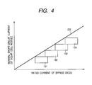
- the compatibility ranks can be indicated using any of the various means including characters, projections and colors. It may be stored in a radio ID chip or the like. It is essential to determine the compatibility rank outside the solar cell module using any means. With reference to FIG. 4, description will be given of a specific method of specifying the compatibility rank codes.
- the axis of ordinate indicates the nominal short-circuit current value of the solar cell module.
- the axis of abscissa indicates the rated current value of the bypass diodes.
- a straight line 200 represents the minimum required rated current value of the bypass diodes used for a solar cell module having a certain short-circuit current value.
- Rectangular areas denoted by 101 to 104 each represent a compatibility rank. Each of the rectangular areas 101 to 104 has its upper left vertex on the straight line 200 or close to the straight line 200 so that it does not project across the line 200. The rectangles do not overlap one another.
- each rectangular area may be properly determined.
- the lower right part of each rectangular area corresponds to the condition that although the short-circuit current is small, the rated current of the bypass diodes is large. This disadvantageously increases costs.
- the form in FIG. 4 is desirable in which the compatibility rank areas are arranged along the vicinity of the straight line 200.
- the straight line 200 essentially passes through an origin and is used to keep the ratio of the rated current of the bypass diodes to the short-circuit current at a fixed value.
- IEEE 1262-1995 IEEE Recommended Practice for Qualification of Photovoltaic (PV) Modules
- the bypass diodes withstand a current 1.25 times as large as the short-circuit current. If this condition is to be met, the ratio of the rated current of the bypass diodes to the nominal short-circuit current may be 1.25 or more.
- the straight line 200 may correspond to the worst possible condition.
- the essential requirement of the present invention is that the bypass diodes of all the solar cell modules belonging to a certain compatibility rank have a rated current value equal to or larger than the minimum bypass diode rated current value required by the solar cell module having the largest nominal short-circuit current in that rank.
- this requirement corresponds to an area located to the right side of the vertical line of the rectangle of FIG. 4 and below the upper horizontal line of the rectangle.
- trapezoidal areas may be used as shown by 301 to 303 in FIG. 5, or the ranks may be set so that bypass diodes with the same rated current do not belong to multiple ranks, or the areas may be arranged at certain intervals so as to be completely separated from another, i.e., the ranks are arranged like islands.
- the bypass diode rated current value and nominal short-circuit current value of the module contained in any of the above areas are considered to be values in the upper left corner of this area.
- the compatibility code may be considered to correspond to a particular combination of the nominal short-circuit value of the module with the bypass diode rated current value on a one-to-one basis.
- the short-circuit current of the solar cell module is generally proportional to its maximum output and optimum operation current.
- their values can be used as ranking parameters in place of the short-circuit current value.
- this ranking is also based on the relationship between the short-circuit current and the bypass diode rated current.
- compatibility ranks or compatibility codes determined as described above.
- the applications of the compatibility ranks are classified into two categories; in one of the categories, the modules belonging to different ranks are not geometrically compatible with one another, and in the other category, the modules are differently colored for visibility.
- the means for indicating electric compatibility is preferably provided on the electric output connection section and/or the weather-resistant enclosure. Then, when replacing the solar cell module with a new one, even a person having no advanced expert knowledge can easily check the modules for electric compatibility. Consequently, the solar cell module can be replaced stably and easily.
- FIG. 1 shows an example of a solar cell module according to the present example.
- the solar cell module 2 shown in FIG. 1 is based on what is called a super straight system. Solar cells are sealed between a front surface protective glass and a back surface laminate sheet with a weather-resistant resin. The periphery of the module 2 is protected by a metal frame 3 so as to be rigid.
- the metal frame 3 is provided with a projection 1a and a hole portion 1b into which the projection is fitted, the projection 1a and the hole portion 1b being composed of a bolt and a nut, respectively.
- the positions of the projection 1a and hole portion 1b correspond to the compatibility rank codes.
- compatibility rank codes were assigned as described below. This assignment corresponds to the form shown in FIG. 4.
- the module outside the areas e.g., the module having a bypass diode rated current of 7 A and a nominal short-circuit current of 5.6 A is not classified into A or B.
- Such module is what is called “out of standard” and is not ensured to be safely used with the group of the modules in the present example.
- compatibility codes it is desirable to define compatibility codes at several-A increments as described above.
- FIG. 6 shows a solar cell array made by combining solar cell modules each of which is shown in FIG. 1 (the cable 5 and the connector 4 are not shown).
- Each projection 1a is fitted into the corresponding hole portion 1b to assemble the modules into the array without creating any gaps. If the projection is not positioned so as to be fitted into the corresponding hole portion, the corresponding modules cannot be assembled together. Accordingly, a person having no advanced expert knowledge can recognize incompatibility.
- This arrangement is only an example.
- Various changes may be made to the positions of the projection and hole portion on the frame and the shapes as well as the numbers of projections and hole positions without departing from the spirits or objects of the present invention.
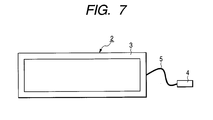
- the conventional solar cell module as shown in FIG. 7 is not provided with any members for compatibility, and therefore erroneous replacement operation of the conventional module may be performed.
- a connector of the module is shaped to correspond to a compatibility rank code.
- FIG. 2 shows an example of a solar cell module according to the present example.
- the compatibility rank code is provided as described in the above example.
- a male connector 41 is provided with a projection 11a shaped to correspond to an appropriate compatibility rank.
- a female connector 42 is provided with a hole portion 11b shaped to correspond to the appropriate compatibility rank.
- FIG. 3 shows an example of a solar cell module according to the present example.
- the solar cell module 2 shown in FIG. 3 is provided with a tag 12 on its cable portion, the tag having a color corresponding to an appropriate compatibility rank.
- the color of the tag 12 is arbitrary. Colors such as red, black, yellow and blue may be properly determined for the respective ranks described above.
- a material for the tag and the position at which the tag is provided are not restricted. Radio ID chips, which have recently been popular, may be used. However, for easy recognition, direct display based on colors or the like is more suitable for the implementation of the present invention.
- As an alternative embodiment for providing visibility based on the compatibility codes it is possible to, for example, impress seals on the cables or connectors or to use characters or symbols. With characters, a single alphabet standing for each rank may be placed on a well-known rate display label or the like.
- the compatibility ranks can be more easily recognized by providing visibility based on the compatibility codes, while simultaneously improving the geometric compatibility as in the case with the previously described example. Therefore, solar cell modules can be very efficiently replaced with new compatible solar cell modules.
- the solar cell module according to the present invention has means (member or site) for indicating electric compatibility determined on the basis of the nominal short-circuit current value of the solar cells and the rated current value of the bypass diodes. This enables the easy selection of a solar cell module having good electrical compatibility, i.e., a solar cell module that can be conveniently used for replacement. Therefore, compatibility can be very easily checked in the field.
- the present invention provides a solar cell module comprising one or more solar cells, one or more bypass diodes, an electric output connection section, and a weather-resistant enclosure, characterized in that a projecting portion and a hole portion which are to be connected to each other and which have predetermined sizes are provided at predetermined positions, as means for indicating electrical compatibility determined on the basis of the rated current value of the bypass diode and the nominal short-circuit current value of the solar cell module. This allows even a user without any advanced technical knowledge to replace a solar cell module safely and easily.
Landscapes
- Photovoltaic Devices (AREA)
Applications Claiming Priority (4)
| Application Number | Priority Date | Filing Date | Title |
|---|---|---|---|
| JP2002330158 | 2002-11-14 | ||
| JP2002330158 | 2002-11-14 | ||
| JP2003371764A JP2004179637A (ja) | 2002-11-14 | 2003-10-31 | 太陽電池モジュール |
| JP2003371764 | 2003-10-31 |
Publications (2)
| Publication Number | Publication Date |
|---|---|
| EP1420459A2 true EP1420459A2 (de) | 2004-05-19 |
| EP1420459A3 EP1420459A3 (de) | 2009-04-29 |
Family
ID=32179153
Family Applications (1)
| Application Number | Title | Priority Date | Filing Date |
|---|---|---|---|
| EP03025984A Withdrawn EP1420459A3 (de) | 2002-11-14 | 2003-11-13 | Solarzellenmodul |
Country Status (3)
| Country | Link |
|---|---|
| US (1) | US20040144418A1 (de) |
| EP (1) | EP1420459A3 (de) |
| JP (1) | JP2004179637A (de) |
Families Citing this family (7)
| Publication number | Priority date | Publication date | Assignee | Title |
|---|---|---|---|---|
| US7612283B2 (en) * | 2002-07-09 | 2009-11-03 | Canon Kabushiki Kaisha | Solar power generation apparatus and its manufacturing method |
| JP2004336944A (ja) * | 2003-05-09 | 2004-11-25 | Canon Inc | 電力変換装置及び太陽光発電システム |
| JP5196886B2 (ja) * | 2007-06-27 | 2013-05-15 | 京セラ株式会社 | 太陽電池モジュール |
| CN102345350A (zh) * | 2010-08-02 | 2012-02-08 | 泰科电子(上海)有限公司 | 光伏幕墙 |
| CN102185007B (zh) * | 2010-12-02 | 2013-01-02 | 浚鑫科技股份有限公司 | 一种太阳能电池组件制造方法 |
| JP2021090029A (ja) * | 2019-12-06 | 2021-06-10 | 日産自動車株式会社 | 多接合型太陽電池 |
| JP7584072B1 (ja) | 2023-11-17 | 2024-11-15 | 株式会社Pxp | 太陽電池モジュール |
Citations (2)
| Publication number | Priority date | Publication date | Assignee | Title |
|---|---|---|---|---|
| US5571338A (en) | 1993-11-26 | 1996-11-05 | Sanyo Electric Co., Ltd. | Photovoltaic module and a photovoltaic apparatus |
| JP2000164910A (ja) | 1998-09-24 | 2000-06-16 | Sanyo Electric Co Ltd | 太陽電池モジュ―ル |
Family Cites Families (35)
| Publication number | Priority date | Publication date | Assignee | Title |
|---|---|---|---|---|
| US4040867A (en) * | 1976-08-24 | 1977-08-09 | The United States Of America As Represented By The Administrator Of The National Aeronautics And Space Administration | Solar cell shingle |
| FR2503875A1 (fr) * | 1981-04-08 | 1982-10-15 | Cables De Lyon Geoffroy Delore | Procede de jonction de cables sous-marins a fibres optiques |
| JPS5991758A (ja) * | 1982-11-18 | 1984-05-26 | Fujitsu Ltd | 通信制御方式 |
| US4595789A (en) * | 1983-04-30 | 1986-06-17 | Kyocera Corporation | Solar cell assembly |
| JPS6027455A (ja) * | 1983-07-26 | 1985-02-12 | Nippon Steel Corp | ビ−ムブランク連続鋳造用案内ロ−ラ装置 |
| US4718185A (en) * | 1986-11-07 | 1988-01-12 | Solar Signage, Inc. | Modular solar generating system |
| ATE170669T1 (de) * | 1992-06-29 | 1998-09-15 | Canon Kk | Harzzusammensetzung zum dichten und eine mit dichtharzzusammensetzung bedeckte halbleitervorrichtung |
| JP3241822B2 (ja) * | 1992-10-09 | 2001-12-25 | シャープ株式会社 | 太陽電池モジュールの安全装置 |
| US5998729A (en) * | 1997-04-11 | 1999-12-07 | Canon Kabushiki Kaisha | Solar cell module having improved flexibility |
| JPH10322885A (ja) * | 1997-05-14 | 1998-12-04 | Canon Inc | 太陽光発電装置 |
| JPH1154776A (ja) * | 1997-06-05 | 1999-02-26 | Canon Inc | 太陽電池の発電量を予測する方法およびその装置 |
| JPH11251615A (ja) * | 1998-03-03 | 1999-09-17 | Canon Inc | 融雪機能付き太陽光発電システム |
| JPH11261095A (ja) * | 1998-03-11 | 1999-09-24 | Canon Inc | 太陽電池モジュール、その製造方法、その設置方法及び太陽光発電システム |
| JP2000059986A (ja) * | 1998-04-08 | 2000-02-25 | Canon Inc | 太陽電池モジュ―ルの故障検出方法および装置ならびに太陽電池モジュ―ル |
| JP2000068537A (ja) * | 1998-06-12 | 2000-03-03 | Canon Inc | 太陽電池モジュ―ル、ストリングおよびシステムならびに管理方法 |
| JP2000286437A (ja) * | 1998-06-12 | 2000-10-13 | Canon Inc | 太陽電池モジュールおよび製造方法 |
| US6218606B1 (en) * | 1998-09-24 | 2001-04-17 | Sanyo Electric Co., Ltd. | Solar cell module for preventing reverse voltage to solar cells |
| JP3697121B2 (ja) * | 1998-10-15 | 2005-09-21 | キヤノン株式会社 | 太陽光発電装置およびその制御方法 |
| JP2000228529A (ja) * | 1998-11-30 | 2000-08-15 | Canon Inc | 過電圧防止素子を有する太陽電池モジュール及びこれを用いた太陽光発電システム |
| US6291761B1 (en) * | 1998-12-28 | 2001-09-18 | Canon Kabushiki Kaisha | Solar cell module, production method and installation method therefor and photovoltaic power generation system |
| JP3809316B2 (ja) * | 1999-01-28 | 2006-08-16 | キヤノン株式会社 | 太陽光発電装置 |
| JP3604948B2 (ja) * | 1999-04-23 | 2004-12-22 | キヤノン株式会社 | 太陽電池アレイ、その修繕方法及び太陽電池発電システム |
| AU755700B2 (en) * | 1999-11-29 | 2002-12-19 | Canon Kabushiki Kaisha | Power generation system, and method for installing the same |
| US6593520B2 (en) * | 2000-02-29 | 2003-07-15 | Canon Kabushiki Kaisha | Solar power generation apparatus and control method therefor |
| JP2001345472A (ja) * | 2000-03-29 | 2001-12-14 | Canon Inc | 太陽電池モジュールの検査方法、検査装置及び製造方法、太陽光発電システムの点検方法及び点検装置、並びに絶縁抵抗測定器及び耐電圧試験器 |
| JP2002009326A (ja) * | 2000-06-26 | 2002-01-11 | Kanegafuchi Chem Ind Co Ltd | 二極防水コネクタ及びこれを用いた太陽電池モジュールの配線構造 |
| JP2002112459A (ja) * | 2000-09-29 | 2002-04-12 | Canon Inc | 太陽電池モジュールおよび発電装置 |
| JP2002111038A (ja) * | 2000-09-29 | 2002-04-12 | Canon Inc | 太陽電池モジュールおよびその製造方法、並びに、発電装置 |
| JP4463963B2 (ja) * | 2000-09-29 | 2010-05-19 | キヤノン株式会社 | 系統連系装置 |
| JP2002142462A (ja) * | 2000-10-30 | 2002-05-17 | Canon Inc | 電力変換装置およびその盗難防止方法 |
| JP4137415B2 (ja) * | 2000-11-21 | 2008-08-20 | シャープ株式会社 | 太陽電池セルの交換方法 |
| JP2002165357A (ja) * | 2000-11-27 | 2002-06-07 | Canon Inc | 電力変換装置およびその制御方法、および発電システム |
| JP2002354678A (ja) * | 2001-05-29 | 2002-12-06 | Canon Inc | 発電装置およびその制御方法 |
| JP2003333861A (ja) * | 2002-05-10 | 2003-11-21 | Canon Inc | 電源装置およびその設計方法、並びに、発電装置 |
| JP2004079997A (ja) * | 2002-06-19 | 2004-03-11 | Canon Inc | 発電システム及び発電装置 |
-
2003
- 2003-10-31 JP JP2003371764A patent/JP2004179637A/ja active Pending
- 2003-11-12 US US10/704,590 patent/US20040144418A1/en not_active Abandoned
- 2003-11-13 EP EP03025984A patent/EP1420459A3/de not_active Withdrawn
Patent Citations (2)
| Publication number | Priority date | Publication date | Assignee | Title |
|---|---|---|---|---|
| US5571338A (en) | 1993-11-26 | 1996-11-05 | Sanyo Electric Co., Ltd. | Photovoltaic module and a photovoltaic apparatus |
| JP2000164910A (ja) | 1998-09-24 | 2000-06-16 | Sanyo Electric Co Ltd | 太陽電池モジュ―ル |
Also Published As
| Publication number | Publication date |
|---|---|
| JP2004179637A (ja) | 2004-06-24 |
| US20040144418A1 (en) | 2004-07-29 |
| EP1420459A3 (de) | 2009-04-29 |
Similar Documents
| Publication | Publication Date | Title |
|---|---|---|
| US12212146B2 (en) | Solar cell assembly | |
| US12057806B2 (en) | Diode-included connector, photovoltaic laminate and photovoltaic assembly using same | |
| US6541696B2 (en) | Solar cell and fabrication method thereof | |
| JPH09148613A (ja) | 太陽電池モジュール | |
| CA1198770A (en) | Interconnection of primary cells | |
| US20130340812A1 (en) | High voltage semiconductor based wafer and a solar module having integrated electronic devices | |
| US9018518B2 (en) | Solar module arrays and diode cable | |
| KR20160141763A (ko) | 광전지 모듈 | |
| EP1420459A2 (de) | Solarzellenmodul | |
| US12328953B2 (en) | Solar cell module | |
| CN117795845A (zh) | 光伏屋顶瓦连接构造 | |
| JP2003332608A (ja) | 太陽電池アレイの補修方法 | |
| US12609651B2 (en) | Photovoltaic module and a method of manufacturing the same | |
| US20250040258A1 (en) | Two-terminal tandem solar module | |
| EP4651677A1 (de) | Solarzellenmodul und stromerzeugungssystem | |
| US20250241074A1 (en) | Monolithic photovoltaic solar panel with micro-pv cells and integrated, monolithic bypass diodes | |
| JP2017011914A (ja) | 太陽光発電システム |
Legal Events
| Date | Code | Title | Description |
|---|---|---|---|
| PUAI | Public reference made under article 153(3) epc to a published international application that has entered the european phase |
Free format text: ORIGINAL CODE: 0009012 |
|
| AK | Designated contracting states |
Kind code of ref document: A2 Designated state(s): AT BE BG CH CY CZ DE DK EE ES FI FR GB GR HU IE IT LI LU MC NL PT RO SE SI SK TR |
|
| AX | Request for extension of the european patent |
Extension state: AL LT LV MK |
|
| PUAL | Search report despatched |
Free format text: ORIGINAL CODE: 0009013 |
|
| AK | Designated contracting states |
Kind code of ref document: A3 Designated state(s): AT BE BG CH CY CZ DE DK EE ES FI FR GB GR HU IE IT LI LU MC NL PT RO SE SI SK TR |
|
| AX | Request for extension of the european patent |
Extension state: AL LT LV MK |
|
| 17P | Request for examination filed |
Effective date: 20091029 |
|
| 17Q | First examination report despatched |
Effective date: 20091118 |
|
| AKX | Designation fees paid |
Designated state(s): AT BE BG CH CY CZ DE DK EE ES FI FR GB GR HU IE IT LI LU MC NL PT RO SE SI SK TR |
|
| STAA | Information on the status of an ep patent application or granted ep patent |
Free format text: STATUS: THE APPLICATION HAS BEEN WITHDRAWN |
|
| 18W | Application withdrawn |
Effective date: 20140226 |