EP1419916B1 - Vorrichtung zum Betätigen einer nach oben schwenkbaren Heckklappe an Kraftfahrzeugen - Google Patents
Vorrichtung zum Betätigen einer nach oben schwenkbaren Heckklappe an Kraftfahrzeugen Download PDFInfo
- Publication number
- EP1419916B1 EP1419916B1 EP03022765A EP03022765A EP1419916B1 EP 1419916 B1 EP1419916 B1 EP 1419916B1 EP 03022765 A EP03022765 A EP 03022765A EP 03022765 A EP03022765 A EP 03022765A EP 1419916 B1 EP1419916 B1 EP 1419916B1
- Authority
- EP
- European Patent Office
- Prior art keywords
- tailgate
- linear drive
- hinges
- vehicle body
- force deflection
- Prior art date
- Legal status (The legal status is an assumption and is not a legal conclusion. Google has not performed a legal analysis and makes no representation as to the accuracy of the status listed.)
- Expired - Lifetime
Links
Images


Classifications
-
- E—FIXED CONSTRUCTIONS
- E05—LOCKS; KEYS; WINDOW OR DOOR FITTINGS; SAFES
- E05F—DEVICES FOR MOVING WINGS INTO OPEN OR CLOSED POSITION; CHECKS FOR WINGS; WING FITTINGS NOT OTHERWISE PROVIDED FOR, CONCERNED WITH THE FUNCTIONING OF THE WING
- E05F15/00—Power-operated mechanisms for wings
- E05F15/60—Power-operated mechanisms for wings using electrical actuators
- E05F15/603—Power-operated mechanisms for wings using electrical actuators using rotary electromotors
- E05F15/611—Power-operated mechanisms for wings using electrical actuators using rotary electromotors for swinging wings
- E05F15/63—Power-operated mechanisms for wings using electrical actuators using rotary electromotors for swinging wings operated by swinging arms
-
- E—FIXED CONSTRUCTIONS
- E05—LOCKS; KEYS; WINDOW OR DOOR FITTINGS; SAFES
- E05Y—INDEXING SCHEME ASSOCIATED WITH SUBCLASSES E05D AND E05F, RELATING TO CONSTRUCTION ELEMENTS, ELECTRIC CONTROL, POWER SUPPLY, POWER SIGNAL OR TRANSMISSION, USER INTERFACES, MOUNTING OR COUPLING, DETAILS, ACCESSORIES, AUXILIARY OPERATIONS NOT OTHERWISE PROVIDED FOR, APPLICATION THEREOF
- E05Y2201/00—Constructional elements; Accessories therefor
- E05Y2201/60—Suspension or transmission members; Accessories therefor
- E05Y2201/622—Suspension or transmission members elements
- E05Y2201/624—Arms
- E05Y2201/626—Levers
-
- E—FIXED CONSTRUCTIONS
- E05—LOCKS; KEYS; WINDOW OR DOOR FITTINGS; SAFES
- E05Y—INDEXING SCHEME ASSOCIATED WITH SUBCLASSES E05D AND E05F, RELATING TO CONSTRUCTION ELEMENTS, ELECTRIC CONTROL, POWER SUPPLY, POWER SIGNAL OR TRANSMISSION, USER INTERFACES, MOUNTING OR COUPLING, DETAILS, ACCESSORIES, AUXILIARY OPERATIONS NOT OTHERWISE PROVIDED FOR, APPLICATION THEREOF
- E05Y2900/00—Application of doors, windows, wings or fittings thereof
- E05Y2900/50—Application of doors, windows, wings or fittings thereof for vehicles
- E05Y2900/53—Type of wing
- E05Y2900/546—Tailboards, tailgates or sideboards opening upwards
Definitions
- the invention relates to a device for actuating an upwardly pivotable tailgate on motor vehicles according to the preamble of claim 1.
- a so-called gas spring referred to herein as a gas spring disclosed, which is supported on the body and the tailgate and essentially serves the weight balance of the same in the open state.
- an electromotive opening and closing device on a tailgate which in turn consists of a arranged on the inside of the roof and the hinge axis of the tailgate drive in the form of an electric motor, in turn, by means of a pulley, two guided over the same in a closed loop cables drives, in turn, each actuate a laterally of the tailgate in a guideway of the body slidably guided slider, which is connected in each case via an articulated actuating rod with the tailgate.
- This outdated solution is due to the necessary deflections for the cables and the guide elements as extreme complicated and prone to failure, which in turn results in a high production and maintenance costs.
- the EP 0 959 212 A1 further shows an actuating arrangement for moving parts on vehicles, such as boot covers, wherein the drive means is arranged in the form of a hydraulic cylinder for opening and closing the boot lid within a longitudinal plane of the vehicle body and engages a hinge of the boot lid.
- the drive means is arranged in the form of a hydraulic cylinder for opening and closing the boot lid within a longitudinal plane of the vehicle body and engages a hinge of the boot lid.
- the US 2001/047625 A1 describes a device of the generic type with a linear drive, which in turn has an electro-mechanically operated rack. Furthermore, it is from the US 4,416,094 known per se, an upwardly pivotable window arranged by means of an axially parallel to the upper cross member of the window Linear drive, which in turn comprises a prestressed coil spring to pivot. Finally, out of the EP 1 154 113 A2 a pivot drive in the form of a linear drive for a tailgate of a motor vehicle is known, which is arranged in the roof area near the D-pillar of the vehicle body and parallel to the vehicle longitudinal axis.
- Object of the present invention is to avoid the disadvantages of the described prior art and accordingly in the same improvement to provide a simple and inexpensive device of the type mentioned, which largely excludes losses of storage space and obstruction of the free view respectively on disturbing Dispensed with aggregates or components in the tailgate, on the other hand achieves a more advantageous force application to the flap structure and thus adverse effects, such as twisting avoids the same.
- the device comprises at least one linear drive, in turn, in the ⁇ -direction (vehicle transverse direction) a portion adjacent to the hinges or the upper cross member of the tailgate portion of the vehicle body is arranged, wherein the linear drive by means of two arranged on the vehicle body Kraftumlenkiano with the tailgate and / or the hinges, a pivoting movement of the tailgate realoaned or supporting, in operative connection, and wherein the power deflection is realized by the linear drive on the tailgate according to a slide principle.
- the linear drive can be designed as an active or passive acting linear drive.
- the linear drive and the Kraftumlenkiata act on at least two spaced attack points on the tailgate and / or their hinges by the linear drive is frontally suspended from the two Kraftumlenk instituten.
- At least one further, but passive-acting linear drive in the form of a gas spring can be assigned to an actively acting linear drive.
- the further passive-acting linear drive in the form of the gas spring is also arranged in the Y direction (vehicle transverse direction) and is operatively connected to the tailgate and / or their hinges via the force deflecting elements of the actively acting linear drive or via their own force deflection elements ,
- Fig. 1 schematically shows the rear view of a motor vehicle, in this case a combined vehicle with an upwardly pivoted tailgate 1, which in turn is connected in a conventional manner by means of overhead hinges 2 to the vehicle body 3 and by means of a device for actuating the tailgate 1 in the form of a linear drive 4 in Open position is held.
- the linear drive 4 extends on one side between the motor vehicle body 3 and the tailgate 1 and is articulated thereon.
- linear actuators 4 have both active-acting and passive acting linear actuators 4a; 4b proven, with actively acting linear actuators 4a hydraulically, pneumatically or electrically (electric motor) can be operated.
- Hydraulically and pneumatically operated linear drives 4a are usually designed as so-called piston-cylinder units.
- Electrically operated linear drives 4a may have a guided in a driven threaded nut threaded rod, which in turn is axially moved by rotation of the threaded nut, as well as a standing with a pinion in operative connection rack is conceivable (not shown).
- a tailgate 1 is first unlocked, for example, after actuation of a switch and subsequently moved by activation of the linear actuator 4a in an open position and finally after repeated actuation of a switch in the starting position (closed position) moves back and locked again.
- Passively acting linear actuators 4b are preferably designed as known per se gas spring springs, which in turn consist of a guided in a cylinder piston rod and support the pivotal movement of the tailgate 1 or act as counterbalance and an already manually open tailgate 1 in an open Position.
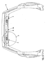
- Fig. 2 schematically shows the inventive arrangement of a single linear drive 4, in this case an actively acting and hydraulically operated linear drive 4a, wherein the media lines 5 are merely indicated for the linear drive 4a and preferably concealed in cavities of the motor vehicle body 3.
- this linear drive 4a is arranged transversely to the vehicle longitudinal axis, accordingly in the Y direction of the motor vehicle body 3 on an adjacent to the hinges 2 and / or the upper cross member 6 of the tailgate 1 portion of the vehicle body 3.
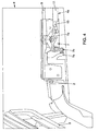
- the force deflecting elements 7 are arranged in the area of the sky 8 of the vehicle body 3 on the rear roof cross member 9 in the immediate vicinity of the hinges 2 ( Fig. 3 ).
- the linear drive 4a and the Kraftumlenkrion 7 should be designed so that the same at two spaced attack points and synchronously and with equal force on the Tailgate 1 and / or their hinges 2 act and the points of attack are to be selected such that the applied force largely evenly distributed to the flap structure and twisting of the tailgate 1 is avoided.
- the active linear drives 4a may have force transmission means 10 in the form of either a piston rod or a toothed or threaded rod. It is therefore self-evident that the linear drive 4a is connected to the power transmission means 10 on the one hand and to the housing, which may be the cylinder 11 of a piston-cylinder unit, for example, on the respectively associated force deflection element 7. It is also conceivable to use per se known double effective linear actuators 4a, which in turn each have two power transmission means 10 which are moved axially in the opposite direction and are connected at their free end to the associated Kraftumlenkelement 7 (not shown in detail).
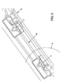
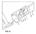
- the embodiment according to the Fig. 5 and 6 differs from the embodiment according to Fig. 3 and 4 merely in that instead of an actively acting linear drive 4a also arranged transversely to the vehicle longitudinal axis, but passive acting linear actuator 4b is used, which in turn is designed as a gas spring and acts on manual opening of the tailgate 1 as weight compensation.
- the further passive-acting linear drive 4b similar to the actively acting linear drive 4a transverse to the vehicle longitudinal axis (Y-direction) and arranged almost parallel to the same and is about the Kraftumlenkiano 7 of the actively acting linear actuator 4a or its own Kraftumlenkiano 7 with the Tailgate 1 and / or their hinges 2 in operative connection.
- a conventional arrangement of the passive-acting linear drive 4b side of the tailgate 1 by accepting the resulting disadvantages already described above is conceivable and also included by the invention.
Landscapes
- Power-Operated Mechanisms For Wings (AREA)
- Body Structure For Vehicles (AREA)
Description
- Die Erfindung betrifft eine Vorrichtung zum Betätigen einer nach oben schwenkbaren Heckklappe an Kraftfahrzeugen nach dem Oberbegriff des Anspruchs 1.
- Insbesondere an Kombi- / Schrägheckfahrzeugen sind seit langem Mittel zum offen halten bzw. selbsttätigen Öffnen von Heckklappen bekannt, deren Scharniere im Bereich des Fahrzeugdaches an tragenden Bauteilen, wie dem hinteren Dachquerträger, befestigt sind.
- Mit der
DE 29 46 259 A1 wird beispielsweise eine sogenannte Gasdruckfeder, hier als Gasfeder bezeichnet, offenbart, die sich an der Karosserie und der Heckklappe abstützt und im Wesentlichen dem Gewichtsausgleich derselben im geöffneten Zustand dient. - Um das Öffnen von großen Heckklappen komfortabler zu gestalten, sind des Weiteren selbsttätig öffnende und schließende Heckklappen bekannt, wobei sowohl elektromotorische als auch hydraulische oder pneumatische Mechanismen vorgeschlagen werden.
- Durch die
DE 37 44 083 C2 ist eine elektromotorische Öffnungs- und Schließvorrichtung an einer Heckklappe bekannt, die ihrerseits sich aus einem an der Innenseite des Daches und neben der Gelenkachse der Heckklappe angeordneten Antrieb in Form eines Elektromotors besteht, der seinerseits mittels einer Seilrolle, zwei über dieselbe in geschlossener Schleife geführte Seilzüge antreibt, die ihrerseits je ein seitlich der Heckklappe in einer Führungsbahn der Karosserie verschiebbar geführtes Gleitstück betätigen, welches jeweils über eine gelenkig gelagerte Betätigungsstange mit der Heckklappe verbunden ist. Diese nicht mehr zeitgemäße Lösung wird aufgrund der erforderlichen Umlenkungen für die Seilzüge sowie der Führungselemente als äußerst kompliziert und störanfällig eingeschätzt, woraus wiederum ein hoher Fertigungs- und Wartungsaufwand resultiert. - Auch durch die
DE 196 15 021 A1 wird eine elektromotorische Öffnungs- und Schließvorrichtung an einer Heckklappe mittels Seilzug offenbart, wobei als Antrieb der Scheibenwischermotor der Heckklappe vorgeschlagen wird. Gleichfalls werden durch diese Druckschrift Hydraulik- oder Pneumatikantriebe vorgeschlagen, wobei vorliegend beidseitig der Heckklappe Hydraulikzylinder angelenkt sind, die sich jeweils mittels einer Kolbenstange an der Karosserie abstützen. Die Hydraulikzylinder selbst sind mit einem vom Scheibenwischermotor betriebenen Hydraulikmotor verbunden. Aufgrund der Tatsache, daß ein Großteil der erforderlichen Aggregate an der Heckklappe selbst angeordnet sind, baut diese äußerst schwer. Weiterhin ist als nachteilig einzuschätzen, daß infolge der Anordnung von zwei getrennt voneinander wirkenden Hydraulikzylindern eine gleichmäßige Krafteinwirkung auf die Heckklappe nicht immer gewährleistet ist und damit ein nachteiliges Verwinden derselben nicht ausgeschlossen werden kann, woraus in der Praxis wiederum erhebliche Verstärkungsmaßnahmen an der Heckklappe resultieren. - In Verbesserung vorstehender Lösung wurden gemäß der
US 6,115,965 wesentliche Aggregateteile der Hydraulikanlage in den Kofferraum des Kraftfahrzeugs verlegt. Als nachteilig ist jedoch auch hier die störende Anordnung der Hydraulikzylinder seitlich der Heckklappe einzuschätzen. - Die
EP 0 959 212 A1 zeigt fernerhin eine Betätigungsanordnung für bewegliche Teile an Fahrzeugen, wie Heckdeckel, wobei die Antriebseinrichtung in Form eines Hydraulikzylinders zum Öffnen und Schließen des Heckdeckels innerhalb einer Längsebene der Kraftfahrzeugkarosserie angeordnet ist und an einem Scharnier des Heckdeckels angreift. Auch hier sind bei einseitiger Kraftaufbringung Verwindungen des Heckdeckels nicht auszuschließen. Des Weiteren sind durch die Anordnung des Hydraulikzylinders beispielsweise im Kofferraum Verluste an Stauraum zu verzeichnen. - Die
US 2001/047625 A1 beschreibt eine Vorrichtung der gattungsgemäßen Art mit einem Linearantrieb, der seinerseits eine elektro-mechanisch betrieben Zahnstange aufweist. Weiterhin ist es aus derUS 4 416 094 A an sich bekannt, ein nach oben schwenkbares Fenster mittels eines achsparallel zu dem oberen Querholm des Fensters angeordneten Linearantriebs, der seinerseits eine vorgespannten Schraubenfeder umfaßt, zu verschwenken. Schließlich ist aus derEP 1 154 113 A2 ein Schwenkantrieb in Form eines Linearantriebs für eine Heckklappe eines Kraftfahrzeugs bekannt, welcher im Dachbereich nahe der D-Säule der Fahrzeugkarosserie und parallel zur Fahrzeuglängsachse angeordnet ist. - Aufgabe der vorliegender Erfindung ist es, die Nachteile des geschilderten Standes der Technik zu vermeiden und demgemäß in Verbesserung desselben eine einfache und kostengünstige Vorrichtung der eingangs genannten Gattung zu schaffen, die zum einen Verluste an Stauraum und eine Behinderung der freien Durchsicht weitestgehend ausschließt respektive auf störende Aggregate bzw. Bauteile im Bereich der Heckklappe verzichtet, zum anderen eine vorteilhaftere Kraftaufbringung auf die Klappenstruktur erzielt und demgemäß nachteilige Effekte, wie Verwindungen derselben vermeidet.
- Ausgehend von einer Vorrichtung zum Betätigen einer nach oben schwenkbaren Heckklappe an Kraftfahrzeugen, wobei die Hecklappe mittels Scharnieren an der Kraftfahrzeugkarosserie gelagert ist, wird die gestellte Aufgabe dadurch gelöst, daß die Vorrichtung zumindest einen Linearantrieb umfaßt, der seinerseits in γ-Richtung (Fahrzeugquerrichtung) an einem zu den Scharnieren oder dem oberen Querholm der Heckklappe benachbarten Abschnitt der Kraftfahrzeugkarosserie angeordnet ist, wobei der Linearantrieb mittels zweier an der Kraftfahrzeugkarosserie angeordneter Kraftumlenkelemente mit der Heckklappe und/oder den Scharnieren, eine Schwenkbewegung der Heckklappe realisierend oder unterstützend, in Wirkverbindung steht, und wobei die Kraftumlenkung vom Linearantrieb auf die Heckklappe nach einem Schieberprinzip realisiert ist. Der Linearantrieb kann als aktiv oder passiv wirkender Linearantrieb ausgebildet sein.
- In Weiterbildung der Erfindung kann vorgesehen sein, daß der Linearantrieb und die Kraftumlenkelemente an wenigstens zwei voneinander beabstandeten Angriffspunkten auf die Heckklappe und/oder deren Scharniere einwirken, indem der Linearantrieb stirnseitig an den beiden Kraftumlenkelementen aufgehängt ist.
- Gemäß einer weiteren vorteilhaften Ausgestaltung der Erfindung kann einem aktiv wirkenden Linearantrieb wenigstens ein weiterer, jedoch passiv wirkender Linearantrieb in Form einer Gasdruckfeder zugeordnet sein. Schließlich wird es als zweckmäßig erachtet, daß der weitere passiv wirkende Linearantrieb in Form der Gasdruckfeder ebenfalls in Y-Richtung (Fahrzeugquerrichtung) angeordnet ist und über die Kraftumlenkelemente des aktiv wirkenden Linearantriebs oder über eigene Kraftumlenkelemente mit der Heckklappe und/oder deren Scharnieren in Wirkverbindung steht.
- Die Erfindung wird nachstehend anhand der in den Zeichnungen schematisch dargestellten Ausführungsbeispiele näher erläutert. Es zeigen:
- Figur 1
- die Heckansicht eines mit einer nach oben schwenkbaren Heckklappe versehenen Kombifahrzeuges mit einer herkömmlichen Anordnung einer Vorrichtung zum Betätigen der Heckklappe,
- Figur 2
- die Heckansicht des Kombifahrzeuges nach
Fig. 1 mit der schematischen Ansicht der Vorrichtung zum Betätigen der Heckklappe in einer ersten Ausführungsform, - Figur 3
- den Schnitt I-I nach
Fig. 2 , - Figur 4
- die Einzelheit "Y" nach
Fig. 3 mit der schematischen Ansicht eines geeigneten Kraftumlenkelementes, - Figur 5
- die Vorrichtung zum Betätigen der Heckklappe in einer weiteren Ausführungsform,
- Figur 6
- die Einzelheit "Z" nach
Fig. 5 , - Figur 7
- die schematische Darstellung einer weitere Ausführungsform eines Kraftumlenkelementes,
- Figur 8
- den Schnitt II-II nach
Fig. 7 . -
Fig. 1 zeigt schematisch die Heckansicht eines Kraftfahrzeugs, vorliegend eines Kombifahrzeuges mit einer nach oben geschwenkten Heckklappe 1, welche ihrerseits in an sich bekannter Weise mittels oben liegender Scharniere 2 an der Kraftfahrzeugkarosserie 3 angebunden und mittels einer Vorrichtung zum Betätigen der Heckklappe 1 in Form eines Linearantriebs 4 in Offen-Stellung gehalten ist. Der Linearantrieb 4 erstreckt sich vorliegend einseitig zwischen der Kraftfahrzeugkarosserie 3 und der Heckklappe 1 und ist an diesen angelenkt. - Als Linearantriebe 4 haben sich sowohl aktiv wirkende als auch passiv wirkende Linearantriebe 4a; 4b bewährt, wobei aktiv wirkende Linearantriebe 4a hydraulisch, pneumatisch oder elektrisch (elektromotorisch) betrieben sein können. Hydraulisch und pneumatisch betriebene Linearantriebe 4a sind üblicherweise als sogenannte Kolben-Zylinder-Einheiten ausgebildet. Elektrisch betriebene Linearantriebe 4a können dagegen eine in einer angetriebenen Gewindemutter geführte Gewindestange aufweisen, die ihrerseits durch Drehung der Gewindemutter axial bewegt wird, ebenso ist auch eine mit einem Ritzel in Wirkverbindung stehende Zahnstange denkbar (nicht näher dargestellt). Mittels aktiv wirkender Linearantriebe 4a wird eine Heckklappe 1 beispielsweise nach Betätigung eines Schalters zunächst entriegelt sowie nachfolgend durch Aktivierung des Linearantriebs 4a in eine Offen-Stellung bewegt und abschließend nach nochmaliger Betätigung eines Schalters in die Ausgangsstellung (Geschlossen-Stellung) zurück bewegt und wieder verriegelt.
- Passiv wirkende Linearantriebe 4b sind für vorliegenden Anwendungsfall vorzugsweise als an sich bekannte Gasdruckfedern ausgebildet, die ihrerseits aus einer in einem Zylinder geführten Kolbenstange bestehen und im Wesentlichen die Schwenkbewegung der Heckklappe 1 unterstützen bzw. als Gewichtsausgleich fungieren und eine bereits manuell geöffnete Heckklappe 1 in einer Offen-Stellung halten.
- Wie bereits oben in den Ausführungen zum Stand der Technik näher dargelegt, ist bei einseitiger Anordnung der Linearantriebe 4a; 4b ein Verwinden der Heckklappe 1 nicht auszuschließen. Unabhängig davon, daß dieser Mißstand durch beidseitige Anordnung von Linearantrieben 4a; 4b sicherlich leicht zu beheben ist, ist insbesondere bei aktiv wirkenden Linearantrieben 4a ein erheblicher technischer Aufwand für die Synchronisation derselben erforderlich. Auch bei Verwendung von zwei beidseitig der Heckklappe 1 angeordneten passiv wirkenden Linearantrieben 4b ist eine hohe Abstimmung derselben zueinander angezeigt. Schließlich wirkt sich diese bekannte Anordnung störend beim Be- bzw. Entladen des Kraftfahrzeuges aus.
- Die
Fig. 2 zeigt demgegenüber schematisch die erfindungsgemäße Anordnung eines einzigen Linearantriebs 4, vorliegend eines aktiv wirkenden und hydraulisch betriebenen Linearantriebs 4a, wobei die Medienleitungen 5 für den Linearantrieb 4a lediglich angedeutet und bevorzugt verdeckt in Hohlräumen der Kraftfahrzeugkarosserie 3 verlegt sind. - Danach ist dieser Linearantrieb 4a quer zur Fahrzeuglängsachse, demgemäß in Y-Richtung der Kraftfahrzeugkarosserie 3 an einem zu den Scharnieren 2 und/oder dem oberen Querholm 6 der Heckklappe 1 benachbarten Abschnitt der Kraftfahrzeugkarosserie 3 angeordnet.
- Variante 1, welche nicht vom Gegenstand der Erfindung erfasst ist:
- Wie in den
Fig. 3 und4 näher gezeigt, steht der Linearantrieb 4a mittels an der Kraftfahrzeugkarosserie 3 angeordneter Kraftumlenkelemente 7 in Form zweier an sich bekannter Hebelsysteme mit der nicht näher dargestellten Heckklappe 1 respektive den Scharnieren 2 in Wirkverbindung. Vorliegend bestehen die Kraftumlenkelemente 7 jeweils aus einem an der Kraftfahrzeugkarosserie 3 schwenkbeweglich angeordneten Schwenkhebel 7a, der einerends mit dem Linearantrieb 4a und anderenends über eine schwenkbeweglich gelagerte Kugelkopfaufnahme 7b mit einer Hebelanbindung 7c des Scharniers 2 verbunden ist. Durch eine axiale Bewegung des Linearantriebs 4a kann somit ein Moment auf die Scharniere 2 aufgebracht und demgemäß eine Schwenkbewegung der Heckklappe 1 realisiert werden. - Variante 2, welche vom Gegenstand der Erfindung erfasst ist:
- Demgegenüber ist in den
Fig. 7 und 8 eine weitere Ausführung einer geeigneten Kraftumlenkung vom Linearantrieb 4a; 4b auf die Scharniere 2 respektive die nicht näher dargestellte Heckklappe 1 gezeigt. Diese ist nach einem sogenannten Schieberprinzip realisiert, wobei zwei keilförmig ausgebildete und aufeinander gleitende Schieberelemente 12; 13 in Seitenführungen 14 und fernerhin zueinander nach Art einer Schwalbenschwanzführung 15 geführt sind. Vorliegend ist das Schieberelement 12 mit dem Linearantrieb 4a; 4b und das Schieberelement 13 mit einem Scharnier 2 verbunden. - In der bevorzugten Ausführungsform sind die Kraftumlenkelemente 7 im Bereich des Himmels 8 der Fahrzeugkarosserie 3 am hinteren Dachquerträger 9 in unmittelbarer Nähe der Scharniere 2 angeordnet (
Fig. 3 ). - Für den Fachmann ist sicherlich leicht nachvollziehbar, daß vorteilhafter Weise der Linearantrieb 4a und die Kraftumlenkelemente 7 so ausgebildet sein sollten, daß dieselben an zwei voneinander beabstandeten Angriffspunkten sowie synchron und mit gleicher Kraft auf die Heckklappe 1 und/oder deren Scharniere 2 einwirken und die Angriffspunkte derart zu wählen sind, daß die einwirkende Kraft weitestgehend gleichmäßig auf die Klappenstruktur verteilt und ein Verwinden der Heckklappe 1 vermieden wird.
- Zum einen wird dieses Erfordernis schon, wie in
Fig. 3 gezeigt, dadurch erfüllt, daß die Angriffspunkte sich im Bereich der nahezu symmetrisch zur Fahrzeuglängsachse und möglichst weit voneinander angeordneten Scharniere 2 befinden, zum anderen in besonders vorteilhafter Weise der Linearantrieb 4a stirnseitig an den beiden Kraftumlenkelementen 7 respektive deren Schwenkhebel 7a aufgehängt ist. Durch diese Maßnahme wird die aufgebrachte Kraft exakt gleichmäßig auf die Scharniere 2 und demgemäß auch auf die Klappenstruktur aufgeteilt. - Wie bereits oben dargetan, können die aktiven Linearantriebe 4a Kraftübertragungsmittel 10 in Form entweder einer Kolbenstange oder einer Zahn- oder Gewindestange aufweisen. Es versteht sich somit von selbst, daß der Linearantrieb 4a zum einen mit dem Kraftübertragungsmittel 10 und zum anderen mit dem Gehäuse, welches beispielsweise der Zylinder 11 einer Kolben-Zylinder-Einheit sein kann, am jeweils zugeordneten Kraftumlenkelement 7 angebunden ist. Ebenso ist es denkbar, an sich bekannte doppelt wirksame Linearantriebe 4a zu verwenden, die ihrerseits jeweils über zwei Kraftübertragungsmittel 10 verfügen, die in entgegengesetzter Richtung axial bewegt werden und mit ihrem freien Ende mit dem zugeordneten Kraftumlenkelement 7 verbunden sind (nicht näher dargestellt).
- Das Ausführungsbeispiel gem den
Fig. 5 und6 unterscheidet sich zum Ausführungsbeispiel nachFig. 3 und4 lediglich dadurch, daß statt eines aktiv wirkenden Linearantriebs 4a ein ebenfalls quer zur Fahrzeuglängsachse angeordneter, jedoch passiv wirkender Linearantrieb 4b Verwendung findet, der seinerseits als Gasdruckfeder ausgebildet ist und bei manuellem Öffnen der Heckklappe 1 als Gewichtsausgleich fungiert. - Als ebenfalls denkbar wird angesehen und durch die Erfindung mit erfaßt, einem aktiv wirkenden Linearantrieb 4a wenigstens einen weiteren passiv wirkenden Linearantrieb 4b zuzuordnen (nicht näher dargestellt). Dieses macht insbesondere dann Sinn, wenn bei Verwendung eines hydraulisch betriebenen Linearantriebs 4a derselbe bei geöffneter Heckklappe 1 drucklos geschaltet wird und somit der passiv wirkende Linearantrieb 4b in Form der Gasdruckfeder die Offen-Stellung der Heckklappe 1 gewährleistet.
- Darüber hinaus wird bei einem Systemausfall des gewählten aktiven Systems eine weitere Betätigung mittels des passiv wirkenden Linearantriebs 4b gewährleistet.
- Hierbei ist in einer bevorzugten Anordnung der weitere passiv wirkende Linearantrieb 4b ähnlich dem aktiv wirkenden Linearantrieb 4a quer zur Fahrzeuglängsachse (Y-Richtung) und nahezu parallel zum demselben angeordnet und steht über die Kraftumlenkelemente 7 des aktiv wirkenden Linearantriebs 4a oder über eigene Kraftumlenkelemente 7 mit der Heckklappe 1 und/oder deren Scharnieren 2 in Wirkverbindung. Selbstverständlich ist auch eine herkömmliche Anordnung des passiv wirkenden Linearantriebs 4b seitlich der Heckklappe 1 unter Inkaufnahme der daraus resultierenden bereits oben beschriebenen Nachteile denkbar und durch die Erfindung ebenfalls mit erfaßt.
Claims (5)
- Vorrichtung zum Betätigen einer nach oben schwenkbaren Heckklappe (1) an Kraftfahrzeugen, wobei die Hecklappe (1) mittels Scharnieren (2) an der Kraftfahrzeugkarosserie (3) gelagert ist,
dadurch gekennzeichnet, daß
die Vorrichtung zumindest einen Linearantrieb (4) umfaßt, der seinerseits in Fahrzeugquerrichtung (y) an einem zu den Scharnieren (2) oder dem oberen Querholm (6) der Heckklappe (1) benachbarten Abschnitt der Kraftfahrzeugkarosserie (3) angeordnet ist, wobei der Linearantrieb (4) mittels zweier an der Kraftfahrzeugkarosserie (3) angeordneter Kraftumlenkelemente (7) mit der Heckklappe (1) und/oder den Scharnieren (2), eine Schwenkbewegung der Heckklappe (1) realisierend oder unterstützend, in Wirkverbindung steht, und wobei die Kraftumlenkung vom Linearantrieb (4) auf die Heckklappe (1) nach einem Schieberprinzip realisiert ist. - Vorrichtung nach Anspruch 1, dadurch gekennzeichnet, daß der Linearantrieb (4) als aktiv oder passiv wirkender Linearantrieb (4a; 4b) ausgebildet ist.
- Vorrichtung nach Anspruch 1 oder 2, dadurch gekennzeichnet, daß der Linearantrieb (4; 4a, 4b) und die Kraftumlenkelemente (7) an wenigstens zwei voneinander beabstandeten Angriffspunkten auf die Heckklappe (1) und/oder deren Scharniere (2) einwirken, indem der Linearantrieb (4; 4a, 4b) stirnseitig an den beiden Kraftumlenkelementen (7) aufgehängt ist.
- Vorrichtung nach einem der Ansprüche 1 bis 3, dadurch gekennzeichnet, daß einem. aktiv wirkenden Linearantrieb (4a) wenigstens ein weiterer, jedoch passiv wirkender Linearantrieb (4b) in Form einer Gasdruckfeder zugeordnet ist.
- Vorrichtung nach Anspruch 4, dadurch gekennzeichnet, daß der weitere passiv wirkende Linearantrieb (4b) in Form der Gasdruckfeder ebenfalls in Fahrzeugquerrichtung (y) angeordnet ist und über die Kraftumlenkelemente (7) des aktiv wirkenden Linearantriebs (4a) oder über eigene Kraftumlenkelemente (7) mit der Heckklappe (1) und/oder deren Scharniere (2) in Wirkverbindung steht.
Applications Claiming Priority (2)
| Application Number | Priority Date | Filing Date | Title |
|---|---|---|---|
| DE10253268 | 2002-11-15 | ||
| DE10253268A DE10253268B4 (de) | 2002-11-15 | 2002-11-15 | Vorrichtung zum Betätigen einer nach oben schwenkbaren Heckklappe an Kraftfahrzeugen |
Publications (2)
| Publication Number | Publication Date |
|---|---|
| EP1419916A1 EP1419916A1 (de) | 2004-05-19 |
| EP1419916B1 true EP1419916B1 (de) | 2011-03-09 |
Family
ID=32115536
Family Applications (1)
| Application Number | Title | Priority Date | Filing Date |
|---|---|---|---|
| EP03022765A Expired - Lifetime EP1419916B1 (de) | 2002-11-15 | 2003-10-10 | Vorrichtung zum Betätigen einer nach oben schwenkbaren Heckklappe an Kraftfahrzeugen |
Country Status (3)
| Country | Link |
|---|---|
| EP (1) | EP1419916B1 (de) |
| AT (1) | ATE500986T1 (de) |
| DE (2) | DE10253268B4 (de) |
Cited By (1)
| Publication number | Priority date | Publication date | Assignee | Title |
|---|---|---|---|---|
| WO2021112954A3 (en) * | 2019-10-09 | 2021-08-05 | Kitty Hawk Corporation | Tilting mechanism with telescoping actuator |
Families Citing this family (6)
| Publication number | Priority date | Publication date | Assignee | Title |
|---|---|---|---|---|
| DE102004032750A1 (de) | 2004-07-07 | 2006-02-09 | Adam Opel Ag | Mehrteilige Heckklappe für ein Kraftfahrzeug |
| DE202005018584U1 (de) * | 2005-11-25 | 2007-03-08 | BROSE SCHLIEßSYSTEME GMBH & CO. KG | Antriebsanordnung zur Betätigung einer Klappe eines Kraftfahrzeugs |
| DE102008014769A1 (de) | 2008-03-18 | 2009-09-24 | Bayerische Motoren Werke Aktiengesellschaft | Betätigungsvorrichtung zum Betätigen einer an einer Fahrzeugkarosserie schwenkbar befestigten Klappe |
| DE202009002622U1 (de) | 2009-02-25 | 2010-07-22 | Brose Fahrzeugteile Gmbh & Co. Kommanditgesellschaft, Hallstadt | Antriebsanordnung zur Betätigung einer Klappe eines Kraftfahrzeugs |
| DE102016210168B3 (de) * | 2016-06-09 | 2017-04-13 | Bayerische Motoren Werke Aktiengesellschaft | Türantrieb für eine Kraftwagentür |
| DE102021133403A1 (de) | 2021-12-16 | 2023-06-22 | Bayerische Motoren Werke Aktiengesellschaft | Antriebssystem für eine schwenkbare Klappe eines Kraftfahrzeugs und Kraftfahrzeug mit einem derartigen Antriebssystem |
Citations (1)
| Publication number | Priority date | Publication date | Assignee | Title |
|---|---|---|---|---|
| US20010047625A1 (en) * | 2000-02-22 | 2001-12-06 | Sedlak David A. | Vehicle liftgate power operating system |
Family Cites Families (8)
| Publication number | Priority date | Publication date | Assignee | Title |
|---|---|---|---|---|
| DE2946259A1 (de) * | 1979-11-16 | 1981-06-04 | Daimler-Benz Ag, 7000 Stuttgart | Schwenkhalterung eines befestigungskopfes, insbesondere fuer eine an einer kraftfahrzeug-heckklappe angreifende, dem gewichtsausgleich dienende gasfeder |
| DE3031318C2 (de) | 1980-08-20 | 1987-02-05 | Braas & Co Gmbh, 6000 Frankfurt | Dachflächenfenster |
| DE3744083A1 (de) * | 1987-12-24 | 1989-07-06 | Opel Adam Ag | Vorrichtung zum motorischen oeffnen und schliessen schwenkbarer karosserieteile von kraftfahrzeugen |
| DE19615021A1 (de) * | 1996-04-17 | 1997-10-23 | Ewald Witte Gmbh & Co Kg | Betätigungshilfe für eine Tür, insbesondere eine Heckklappe an einem Kraftfahrzeug |
| US6115965A (en) * | 1997-12-09 | 2000-09-12 | Dura Convertible Systems | Power operator for vehicle liftgate |
| AT405860B (de) * | 1998-05-20 | 1999-12-27 | Hoerbiger Gmbh | Betätigungsanordnung für bewegliche teile an fahrzeugen |
| DE19933765B4 (de) * | 1999-07-19 | 2015-03-19 | Volkswagen Ag | Schwenklagerung für eine hochschwenkbare Klappe eines Fahrzeugaufbaues |
| US6550839B2 (en) | 2000-05-11 | 2003-04-22 | Delphi Technologies, Inc. | Vehicle pivoting closure power operating assembly |
-
2002
- 2002-11-15 DE DE10253268A patent/DE10253268B4/de not_active Expired - Fee Related
-
2003
- 2003-10-10 EP EP03022765A patent/EP1419916B1/de not_active Expired - Lifetime
- 2003-10-10 AT AT03022765T patent/ATE500986T1/de active
- 2003-10-10 DE DE50313525T patent/DE50313525D1/de not_active Expired - Lifetime
Patent Citations (1)
| Publication number | Priority date | Publication date | Assignee | Title |
|---|---|---|---|---|
| US20010047625A1 (en) * | 2000-02-22 | 2001-12-06 | Sedlak David A. | Vehicle liftgate power operating system |
Cited By (1)
| Publication number | Priority date | Publication date | Assignee | Title |
|---|---|---|---|---|
| WO2021112954A3 (en) * | 2019-10-09 | 2021-08-05 | Kitty Hawk Corporation | Tilting mechanism with telescoping actuator |
Also Published As
| Publication number | Publication date |
|---|---|
| DE50313525D1 (de) | 2011-04-21 |
| DE10253268B4 (de) | 2010-11-25 |
| EP1419916A1 (de) | 2004-05-19 |
| ATE500986T1 (de) | 2011-03-15 |
| DE10253268A1 (de) | 2004-05-27 |
Similar Documents
| Publication | Publication Date | Title |
|---|---|---|
| EP2065260B1 (de) | Türkantenschutzeinrichtung | |
| DE3744083C2 (de) | ||
| DE102020209607B4 (de) | Verschlussanordnung zum Verschließen einer Tankmulde einer Karosserie eines Kraftfahrzeugs | |
| EP0760304B1 (de) | Verdeck für ein Fahrzeug, insbesondere Personenkraftwagen | |
| EP2477863B1 (de) | Schienenfahrzeug mit frontkupplungsverkleidung | |
| EP2318631B1 (de) | Kraftfahrzeug mit mechanismus zum bewegen einer klappe oder tür | |
| DE102010029065A1 (de) | Türkantenschutzeinrichtung | |
| DE69100488T2 (de) | Schiebetür, insbesondere für Eisenbahnwagen. | |
| DE19941207C1 (de) | Antriebsvorrichtung für ein Schwenkbauteil | |
| DE10253268B4 (de) | Vorrichtung zum Betätigen einer nach oben schwenkbaren Heckklappe an Kraftfahrzeugen | |
| WO2005070715A1 (de) | Heckklappe eines kraftfahrzeugs | |
| DE10105598B4 (de) | Windabweiser für einen Kraftwagen | |
| DE10153724A1 (de) | Fahrzeugklappe | |
| DE102011116174A1 (de) | Anordnung zur Befestigung zumindest einer Hecktür an einer Karosserie eines Fahrzeugs sowie Fahrzeug mit einer derartigen Anordnung | |
| EP1581714B1 (de) | Drehkippfenster mit antriebsvorrichtung | |
| EP1791709B1 (de) | Cabriolet-fahrzeug | |
| DE102007028571A1 (de) | Gleittür und Betätigungsvorrichtung für eine Gleittür eines Fahrzeugs | |
| DE102008061395B4 (de) | Kraftfahrzeug mit Mechanismus zum Bewegen einer Klappe oder Scherentüre | |
| DE102009043375B4 (de) | Fensteranordnung | |
| DE1930485A1 (de) | Schwenkschiebetuer,insbesondere fuer Strassen- und Schienenfahrzeuge | |
| DE102008033478A1 (de) | Abdeckvorrichtung für einen Gepäckraum eines Kraftfahrzeuges | |
| DE102005007728A1 (de) | Hardtop-Verdeck | |
| DE102006030459B4 (de) | Schwenk-Schiebe-Mechanismus für eine Fahrzeugtür | |
| DE102008045899B4 (de) | Kraftfahrzeug mit Mechanismus zum Bewegen einer Klappe mittels eines Motors | |
| DE2751657B1 (de) | Fahrzeugschiebetuer |
Legal Events
| Date | Code | Title | Description |
|---|---|---|---|
| PUAI | Public reference made under article 153(3) epc to a published international application that has entered the european phase |
Free format text: ORIGINAL CODE: 0009012 |
|
| AK | Designated contracting states |
Kind code of ref document: A1 Designated state(s): AT BE BG CH CY CZ DE DK EE ES FI FR GB GR HU IE IT LI LU MC NL PT RO SE SI SK TR |
|
| AX | Request for extension of the european patent |
Extension state: AL LT LV MK |
|
| 17P | Request for examination filed |
Effective date: 20041119 |
|
| AKX | Designation fees paid |
Designated state(s): AT BE BG CH CY CZ DE DK EE ES FI FR GB GR HU IE IT LI LU MC NL PT RO SE SI SK TR |
|
| 17Q | First examination report despatched |
Effective date: 20100415 |
|
| GRAP | Despatch of communication of intention to grant a patent |
Free format text: ORIGINAL CODE: EPIDOSNIGR1 |
|
| GRAS | Grant fee paid |
Free format text: ORIGINAL CODE: EPIDOSNIGR3 |
|
| GRAA | (expected) grant |
Free format text: ORIGINAL CODE: 0009210 |
|
| AK | Designated contracting states |
Kind code of ref document: B1 Designated state(s): AT BE BG CH CY CZ DE DK EE ES FI FR GB GR HU IE IT LI LU MC NL PT RO SE SI SK TR |
|
| REG | Reference to a national code |
Ref country code: GB Ref legal event code: FG4D Free format text: NOT ENGLISH |
|
| REG | Reference to a national code |
Ref country code: CH Ref legal event code: EP |
|
| REG | Reference to a national code |
Ref country code: IE Ref legal event code: FG4D Free format text: LANGUAGE OF EP DOCUMENT: GERMAN |
|
| REF | Corresponds to: |
Ref document number: 50313525 Country of ref document: DE Date of ref document: 20110421 Kind code of ref document: P |
|
| REG | Reference to a national code |
Ref country code: DE Ref legal event code: R096 Ref document number: 50313525 Country of ref document: DE Effective date: 20110421 |
|
| REG | Reference to a national code |
Ref country code: NL Ref legal event code: VDEP Effective date: 20110309 |
|
| PG25 | Lapsed in a contracting state [announced via postgrant information from national office to epo] |
Ref country code: GR Free format text: LAPSE BECAUSE OF FAILURE TO SUBMIT A TRANSLATION OF THE DESCRIPTION OR TO PAY THE FEE WITHIN THE PRESCRIBED TIME-LIMIT Effective date: 20110610 Ref country code: ES Free format text: LAPSE BECAUSE OF FAILURE TO SUBMIT A TRANSLATION OF THE DESCRIPTION OR TO PAY THE FEE WITHIN THE PRESCRIBED TIME-LIMIT Effective date: 20110620 Ref country code: SE Free format text: LAPSE BECAUSE OF FAILURE TO SUBMIT A TRANSLATION OF THE DESCRIPTION OR TO PAY THE FEE WITHIN THE PRESCRIBED TIME-LIMIT Effective date: 20110309 |
|
| PG25 | Lapsed in a contracting state [announced via postgrant information from national office to epo] |
Ref country code: BG Free format text: LAPSE BECAUSE OF FAILURE TO SUBMIT A TRANSLATION OF THE DESCRIPTION OR TO PAY THE FEE WITHIN THE PRESCRIBED TIME-LIMIT Effective date: 20110609 Ref country code: CY Free format text: LAPSE BECAUSE OF FAILURE TO SUBMIT A TRANSLATION OF THE DESCRIPTION OR TO PAY THE FEE WITHIN THE PRESCRIBED TIME-LIMIT Effective date: 20110309 Ref country code: NL Free format text: LAPSE BECAUSE OF FAILURE TO SUBMIT A TRANSLATION OF THE DESCRIPTION OR TO PAY THE FEE WITHIN THE PRESCRIBED TIME-LIMIT Effective date: 20110309 Ref country code: FI Free format text: LAPSE BECAUSE OF FAILURE TO SUBMIT A TRANSLATION OF THE DESCRIPTION OR TO PAY THE FEE WITHIN THE PRESCRIBED TIME-LIMIT Effective date: 20110309 Ref country code: SI Free format text: LAPSE BECAUSE OF FAILURE TO SUBMIT A TRANSLATION OF THE DESCRIPTION OR TO PAY THE FEE WITHIN THE PRESCRIBED TIME-LIMIT Effective date: 20110309 |
|
| REG | Reference to a national code |
Ref country code: IE Ref legal event code: FD4D |
|
| PG25 | Lapsed in a contracting state [announced via postgrant information from national office to epo] |
Ref country code: EE Free format text: LAPSE BECAUSE OF FAILURE TO SUBMIT A TRANSLATION OF THE DESCRIPTION OR TO PAY THE FEE WITHIN THE PRESCRIBED TIME-LIMIT Effective date: 20110309 Ref country code: IE Free format text: LAPSE BECAUSE OF FAILURE TO SUBMIT A TRANSLATION OF THE DESCRIPTION OR TO PAY THE FEE WITHIN THE PRESCRIBED TIME-LIMIT Effective date: 20110309 Ref country code: PT Free format text: LAPSE BECAUSE OF FAILURE TO SUBMIT A TRANSLATION OF THE DESCRIPTION OR TO PAY THE FEE WITHIN THE PRESCRIBED TIME-LIMIT Effective date: 20110711 |
|
| PG25 | Lapsed in a contracting state [announced via postgrant information from national office to epo] |
Ref country code: CZ Free format text: LAPSE BECAUSE OF FAILURE TO SUBMIT A TRANSLATION OF THE DESCRIPTION OR TO PAY THE FEE WITHIN THE PRESCRIBED TIME-LIMIT Effective date: 20110309 Ref country code: SK Free format text: LAPSE BECAUSE OF FAILURE TO SUBMIT A TRANSLATION OF THE DESCRIPTION OR TO PAY THE FEE WITHIN THE PRESCRIBED TIME-LIMIT Effective date: 20110309 Ref country code: RO Free format text: LAPSE BECAUSE OF FAILURE TO SUBMIT A TRANSLATION OF THE DESCRIPTION OR TO PAY THE FEE WITHIN THE PRESCRIBED TIME-LIMIT Effective date: 20110309 |
|
| PLBE | No opposition filed within time limit |
Free format text: ORIGINAL CODE: 0009261 |
|
| STAA | Information on the status of an ep patent application or granted ep patent |
Free format text: STATUS: NO OPPOSITION FILED WITHIN TIME LIMIT |
|
| 26N | No opposition filed |
Effective date: 20111212 |
|
| PG25 | Lapsed in a contracting state [announced via postgrant information from national office to epo] |
Ref country code: DK Free format text: LAPSE BECAUSE OF FAILURE TO SUBMIT A TRANSLATION OF THE DESCRIPTION OR TO PAY THE FEE WITHIN THE PRESCRIBED TIME-LIMIT Effective date: 20110309 |
|
| REG | Reference to a national code |
Ref country code: DE Ref legal event code: R097 Ref document number: 50313525 Country of ref document: DE Effective date: 20111212 |
|
| BERE | Be: lapsed |
Owner name: VOLKSWAGEN A.G. Effective date: 20111031 |
|
| PG25 | Lapsed in a contracting state [announced via postgrant information from national office to epo] |
Ref country code: IT Free format text: LAPSE BECAUSE OF FAILURE TO SUBMIT A TRANSLATION OF THE DESCRIPTION OR TO PAY THE FEE WITHIN THE PRESCRIBED TIME-LIMIT Effective date: 20110309 Ref country code: MC Free format text: LAPSE BECAUSE OF NON-PAYMENT OF DUE FEES Effective date: 20111031 |
|
| REG | Reference to a national code |
Ref country code: CH Ref legal event code: PL |
|
| GBPC | Gb: european patent ceased through non-payment of renewal fee |
Effective date: 20111010 |
|
| REG | Reference to a national code |
Ref country code: FR Ref legal event code: ST Effective date: 20120629 |
|
| PG25 | Lapsed in a contracting state [announced via postgrant information from national office to epo] |
Ref country code: CH Free format text: LAPSE BECAUSE OF NON-PAYMENT OF DUE FEES Effective date: 20111031 Ref country code: LI Free format text: LAPSE BECAUSE OF NON-PAYMENT OF DUE FEES Effective date: 20111031 Ref country code: BE Free format text: LAPSE BECAUSE OF NON-PAYMENT OF DUE FEES Effective date: 20111031 |
|
| PG25 | Lapsed in a contracting state [announced via postgrant information from national office to epo] |
Ref country code: FR Free format text: LAPSE BECAUSE OF NON-PAYMENT OF DUE FEES Effective date: 20111102 Ref country code: GB Free format text: LAPSE BECAUSE OF NON-PAYMENT OF DUE FEES Effective date: 20111010 |
|
| REG | Reference to a national code |
Ref country code: AT Ref legal event code: MM01 Ref document number: 500986 Country of ref document: AT Kind code of ref document: T Effective date: 20111010 |
|
| PG25 | Lapsed in a contracting state [announced via postgrant information from national office to epo] |
Ref country code: AT Free format text: LAPSE BECAUSE OF NON-PAYMENT OF DUE FEES Effective date: 20111010 |
|
| PG25 | Lapsed in a contracting state [announced via postgrant information from national office to epo] |
Ref country code: LU Free format text: LAPSE BECAUSE OF NON-PAYMENT OF DUE FEES Effective date: 20111010 |
|
| PG25 | Lapsed in a contracting state [announced via postgrant information from national office to epo] |
Ref country code: TR Free format text: LAPSE BECAUSE OF FAILURE TO SUBMIT A TRANSLATION OF THE DESCRIPTION OR TO PAY THE FEE WITHIN THE PRESCRIBED TIME-LIMIT Effective date: 20110309 |
|
| PG25 | Lapsed in a contracting state [announced via postgrant information from national office to epo] |
Ref country code: HU Free format text: LAPSE BECAUSE OF FAILURE TO SUBMIT A TRANSLATION OF THE DESCRIPTION OR TO PAY THE FEE WITHIN THE PRESCRIBED TIME-LIMIT Effective date: 20110309 |
|
| PGFP | Annual fee paid to national office [announced via postgrant information from national office to epo] |
Ref country code: DE Payment date: 20161031 Year of fee payment: 14 |
|
| REG | Reference to a national code |
Ref country code: DE Ref legal event code: R119 Ref document number: 50313525 Country of ref document: DE |
|
| PG25 | Lapsed in a contracting state [announced via postgrant information from national office to epo] |
Ref country code: DE Free format text: LAPSE BECAUSE OF NON-PAYMENT OF DUE FEES Effective date: 20180501 |