EP1414266B1 - Active acoustic devices - Google Patents
Active acoustic devices Download PDFInfo
- Publication number
- EP1414266B1 EP1414266B1 EP04075008A EP04075008A EP1414266B1 EP 1414266 B1 EP1414266 B1 EP 1414266B1 EP 04075008 A EP04075008 A EP 04075008A EP 04075008 A EP04075008 A EP 04075008A EP 1414266 B1 EP1414266 B1 EP 1414266B1
- Authority
- EP
- European Patent Office
- Prior art keywords
- panel
- transducer
- panel member
- edge
- acoustic
- Prior art date
- Legal status (The legal status is an assumption and is not a legal conclusion. Google has not performed a legal analysis and makes no representation as to the accuracy of the status listed.)
- Expired - Lifetime
Links
- 238000005452 bending Methods 0.000 claims description 25
- 230000009471 action Effects 0.000 claims description 21
- 238000000034 method Methods 0.000 claims description 12
- 238000009826 distribution Methods 0.000 claims description 9
- 230000003993 interaction Effects 0.000 claims description 7
- 230000006835 compression Effects 0.000 claims description 4
- 238000007906 compression Methods 0.000 claims description 4
- 230000001419 dependent effect Effects 0.000 claims description 4
- 230000008878 coupling Effects 0.000 claims description 3
- 238000010168 coupling process Methods 0.000 claims description 3
- 238000005859 coupling reaction Methods 0.000 claims description 3
- 230000005284 excitation Effects 0.000 description 16
- 239000011162 core material Substances 0.000 description 15
- 230000000694 effects Effects 0.000 description 14
- 239000000463 material Substances 0.000 description 9
- 230000003287 optical effect Effects 0.000 description 6
- 239000000725 suspension Substances 0.000 description 6
- 239000004964 aerogel Substances 0.000 description 4
- 230000009286 beneficial effect Effects 0.000 description 4
- 238000013461 design Methods 0.000 description 4
- 230000006870 function Effects 0.000 description 4
- 239000011521 glass Substances 0.000 description 4
- 238000011835 investigation Methods 0.000 description 4
- 230000033001 locomotion Effects 0.000 description 4
- VYPSYNLAJGMNEJ-UHFFFAOYSA-N Silicium dioxide Chemical compound O=[Si]=O VYPSYNLAJGMNEJ-UHFFFAOYSA-N 0.000 description 3
- 238000000576 coating method Methods 0.000 description 3
- 230000005855 radiation Effects 0.000 description 3
- 230000000007 visual effect Effects 0.000 description 3
- XEEYBQQBJWHFJM-UHFFFAOYSA-N Iron Chemical compound [Fe] XEEYBQQBJWHFJM-UHFFFAOYSA-N 0.000 description 2
- 239000000853 adhesive Substances 0.000 description 2
- 230000001070 adhesive effect Effects 0.000 description 2
- 239000002131 composite material Substances 0.000 description 2
- 230000002708 enhancing effect Effects 0.000 description 2
- 238000007689 inspection Methods 0.000 description 2
- 238000010606 normalization Methods 0.000 description 2
- 230000002093 peripheral effect Effects 0.000 description 2
- 229920003023 plastic Polymers 0.000 description 2
- 230000035899 viability Effects 0.000 description 2
- 229920002799 BoPET Polymers 0.000 description 1
- 239000004966 Carbon aerogel Substances 0.000 description 1
- 239000005041 Mylar™ Substances 0.000 description 1
- NIXOWILDQLNWCW-UHFFFAOYSA-N acrylic acid group Chemical group C(C=C)(=O)O NIXOWILDQLNWCW-UHFFFAOYSA-N 0.000 description 1
- 238000007792 addition Methods 0.000 description 1
- 238000004458 analytical method Methods 0.000 description 1
- 238000013459 approach Methods 0.000 description 1
- 230000003190 augmentative effect Effects 0.000 description 1
- 230000008901 benefit Effects 0.000 description 1
- 230000005540 biological transmission Effects 0.000 description 1
- 230000015572 biosynthetic process Effects 0.000 description 1
- 238000005253 cladding Methods 0.000 description 1
- 239000011248 coating agent Substances 0.000 description 1
- 238000013329 compounding Methods 0.000 description 1
- 150000001875 compounds Chemical class 0.000 description 1
- 238000010276 construction Methods 0.000 description 1
- 238000013016 damping Methods 0.000 description 1
- 230000006735 deficit Effects 0.000 description 1
- 238000011161 development Methods 0.000 description 1
- 230000018109 developmental process Effects 0.000 description 1
- 238000010586 diagram Methods 0.000 description 1
- 230000005520 electrodynamics Effects 0.000 description 1
- 238000005516 engineering process Methods 0.000 description 1
- 235000019547 evenness Nutrition 0.000 description 1
- 238000001914 filtration Methods 0.000 description 1
- 239000012530 fluid Substances 0.000 description 1
- 238000009432 framing Methods 0.000 description 1
- 239000000499 gel Substances 0.000 description 1
- 229910000078 germane Inorganic materials 0.000 description 1
- 230000006872 improvement Effects 0.000 description 1
- 229910052738 indium Inorganic materials 0.000 description 1
- 230000010354 integration Effects 0.000 description 1
- 230000002452 interceptive effect Effects 0.000 description 1
- UQSXHKLRYXJYBZ-UHFFFAOYSA-N iron oxide Inorganic materials [Fe]=O UQSXHKLRYXJYBZ-UHFFFAOYSA-N 0.000 description 1
- 229910052746 lanthanum Inorganic materials 0.000 description 1
- FZLIPJUXYLNCLC-UHFFFAOYSA-N lanthanum atom Chemical compound [La] FZLIPJUXYLNCLC-UHFFFAOYSA-N 0.000 description 1
- 239000004973 liquid crystal related substance Substances 0.000 description 1
- 238000004519 manufacturing process Methods 0.000 description 1
- 238000013017 mechanical damping Methods 0.000 description 1
- 230000007246 mechanism Effects 0.000 description 1
- 229910044991 metal oxide Inorganic materials 0.000 description 1
- 150000004706 metal oxides Chemical class 0.000 description 1
- 230000000116 mitigating effect Effects 0.000 description 1
- 230000004048 modification Effects 0.000 description 1
- 238000012986 modification Methods 0.000 description 1
- 230000007935 neutral effect Effects 0.000 description 1
- 229920000620 organic polymer Polymers 0.000 description 1
- 230000001151 other effect Effects 0.000 description 1
- 239000004033 plastic Substances 0.000 description 1
- 229920000515 polycarbonate Polymers 0.000 description 1
- 239000004417 polycarbonate Substances 0.000 description 1
- 229920000728 polyester Polymers 0.000 description 1
- -1 polyethylene terephthalate Polymers 0.000 description 1
- 229920000139 polyethylene terephthalate Polymers 0.000 description 1
- 239000005020 polyethylene terephthalate Substances 0.000 description 1
- 238000012545 processing Methods 0.000 description 1
- 230000000750 progressive effect Effects 0.000 description 1
- 230000004044 response Effects 0.000 description 1
- 238000000926 separation method Methods 0.000 description 1
- 239000000377 silicon dioxide Substances 0.000 description 1
- 239000011343 solid material Substances 0.000 description 1
- 238000012360 testing method Methods 0.000 description 1
- XOLBLPGZBRYERU-UHFFFAOYSA-N tin dioxide Chemical compound O=[Sn]=O XOLBLPGZBRYERU-UHFFFAOYSA-N 0.000 description 1
- 229910001887 tin oxide Inorganic materials 0.000 description 1
- JPJZHBHNQJPGSG-UHFFFAOYSA-N titanium;zirconium;tetrahydrate Chemical compound O.O.O.O.[Ti].[Zr] JPJZHBHNQJPGSG-UHFFFAOYSA-N 0.000 description 1
- 238000012546 transfer Methods 0.000 description 1
- 239000012780 transparent material Substances 0.000 description 1
Images


Classifications
-
- H—ELECTRICITY
- H04—ELECTRIC COMMUNICATION TECHNIQUE
- H04R—LOUDSPEAKERS, MICROPHONES, GRAMOPHONE PICK-UPS OR LIKE ACOUSTIC ELECTROMECHANICAL TRANSDUCERS; DEAF-AID SETS; PUBLIC ADDRESS SYSTEMS
- H04R7/00—Diaphragms for electromechanical transducers; Cones
- H04R7/26—Damping by means acting directly on free portion of diaphragm or cone
-
- H—ELECTRICITY
- H04—ELECTRIC COMMUNICATION TECHNIQUE
- H04R—LOUDSPEAKERS, MICROPHONES, GRAMOPHONE PICK-UPS OR LIKE ACOUSTIC ELECTROMECHANICAL TRANSDUCERS; DEAF-AID SETS; PUBLIC ADDRESS SYSTEMS
- H04R7/00—Diaphragms for electromechanical transducers; Cones
- H04R7/02—Diaphragms for electromechanical transducers; Cones characterised by the construction
- H04R7/04—Plane diaphragms
- H04R7/045—Plane diaphragms using the distributed mode principle, i.e. whereby the acoustic radiation is emanated from uniformly distributed free bending wave vibration induced in a stiff panel and not from pistonic motion
-
- H—ELECTRICITY
- H04—ELECTRIC COMMUNICATION TECHNIQUE
- H04R—LOUDSPEAKERS, MICROPHONES, GRAMOPHONE PICK-UPS OR LIKE ACOUSTIC ELECTROMECHANICAL TRANSDUCERS; DEAF-AID SETS; PUBLIC ADDRESS SYSTEMS
- H04R2440/00—Bending wave transducers covered by H04R, not provided for in its groups
- H04R2440/05—Aspects relating to the positioning and way or means of mounting of exciters to resonant bending wave panels
-
- H—ELECTRICITY
- H04—ELECTRIC COMMUNICATION TECHNIQUE
- H04R—LOUDSPEAKERS, MICROPHONES, GRAMOPHONE PICK-UPS OR LIKE ACOUSTIC ELECTROMECHANICAL TRANSDUCERS; DEAF-AID SETS; PUBLIC ADDRESS SYSTEMS
- H04R2499/00—Aspects covered by H04R or H04S not otherwise provided for in their subgroups
- H04R2499/10—General applications
- H04R2499/15—Transducers incorporated in visual displaying devices, e.g. televisions, computer displays, laptops
Definitions
- This invention relates to active acoustic devices and more particularly to panel members for which acoustic action or performance relies on beneficial distribution of resonant modes of bending wave action in such a panel member and related surface vibration; and to methods of improving such active acoustic devices.
- distributed mode for such acoustic devices, including acoustic radiators or loudspeakers; and for the term “panel-form” to be taken as inferring such distributed mode action in a panel member unless the context does not permit.
- such panel members operate as distributed mode acoustic radiators relying on bending wave action induced by input means applying mechanical action to the panel member; and resulting excitation of resonant modes of bending wave action causing surface vibration for acoustic output by coupling to ambient fluid, typically air.
- Revelatory teaching regarding such acoustic radiators is given in our International patent application WO97/09842 ; and various of our later patent applications concern useful additions and developments.
- transducer locations have been considered as viably and optimally effective at locations in-board of the panel member to a substantial extent towards but offset from its centre, at least for panels that are substantially isotropic as to bending stiffness and exhibit effectively substantially constant axial anisotropy of bending stiffness(es).
- Aforementioned WO97/09842 gives specific guidance in terms of optimal proportionate co-ordinates for such in-board transducer locations, including alternatives; and preference for different particular co-ordinate combinations when using two or more transducers.
- a distributed mode active acoustic device according to claim 1.
- a distributed mode active acoustic device according to claim 2.
- a suitable acoustic panel member may be transparent or translucent.
- Typical panel members may be generally polygonal often substantially rectangular.
- the transducer may be piezo-electric, electrostatic or electro-mechanical.
- the transducer may be arranged to launch compression waves into the panel edge, and/or to deflect the panel edge laterally to launch transverse bending waves along a panel edge, and/or to apply torsion across a panel corner, and/or to produce linear deflection of a local region of the panel.
- Assessment of acoustic output from panel members may be relative to suitable criteria for acoustic output include as to amount of power output thus efficiency in converting input mechanical vibration (automatically also customary causative electrical drive) into acoustic output, smoothness of power output as measure of even-ness of excitation of resonant mode of bending wave action, inspection of power output as to frequencies of excited resonant modes including number and distribution or spread of those frequencies, each up to all as useful indicators.
- Such assessments of viability of locations for transducer means constitute method aspects of this invention individually and in combination.
- mean square deviation assessment As aid to assessment at least of smoothness of power output, it is further proposed herein to use techniques based on mean square deviation from some reference.
- Use of the inverse of mean square deviation has the benefit of presenting smoothness for assessment according directly to positive values and/or representations.
- a suitable reference can be individual to each case considered, say a median-based, such as represented graphically by a smoothed line through actual measured power output over a frequency range of interest. It is significantly helpful to mean square deviation assessment for the reference to have a normalised standard format; and for the measured acoustic power output to be adjusted to fit that standard format.
- the standard format may be a graphically straight line, preferably a flat straight line thus corresponding to some particular constant reference value; further preferably the same line or value as found naturally to apply to a distributed mode panel member at higher frequencies where modes and modal action are more or most dense.
- This lower acoustic power output at lower frequencies is related to free edge vibration of the panel members as such, and consequential greater loss of lower frequency power, greater proportion of which tends to be poorly radiated and/or dissipated, including effectively short-circuited about free adjacent panel edges.
- these lower frequency power loss effects are significantly greater for panel members with transducer locations at or near their edges and/or lesser stiffnesses - compared with panel members using in-board transducer locations.
- significant mitigation of these effects is available by mounting the panel members surrounded by baffles and/or by clamping at the edges of the panel members. Indeed, spaced localised edge clamps can have usefully selectively beneficial effects relative to frequencies with wavelengths greater than the spacing of the localised edge clamps.
- corner or near-corner excitation involves suitably mass-loading or clamping substantially at a known in-board optimal or preferential drive location, where it appears that such mass-loaded optimal drive location(s) effectively behave(s) to some useful extent as "virtual" source(s) of bending wave vibrations in the member. This latter may not avoid central intrusion by the mass loading but is clearly germane to successful marginal excitation at corners.
- the operating frequency range of interest should be made part of assessment of location for transducer means , i.e. could be different for ranges wholly above and extending below such as 500 Hz.
- Another influencing factor could be presence of an adjacent surface, say behind the panel member at a spacing affecting acoustic performance.
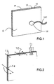
- distributed mode acoustic panel loud-speaker 10 is as described in WO97/09842 with panel member 11 having typical optimal near- (but off-) centre location for drive means transducer 12.
- the sandwich structure shown with core 14 and skins 15, 16 is exemplary only, there being many monolithic and/or reinforced and other structural possibilities. In any event, normal in-board transducer placement potentially limits clear area available, e.g. for such as transmission of light in the case of a transparent or translucent panel.
- Mainly transparent or translucent resonant mode acoustic panel members might use known transparent piezo-electric transducers, e.g. of lanthanum doped titanium zirconate.
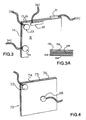
- these are relatively costly, hence the alternative approach thereof by which it is possible to leave the resonant mode acoustic panel member 10 mainly clear and unobstructed by optimising loudspeaker design from a choice of four types of excitation shown in Figure 2 directed to the margins or perimeter of the panel, and labelled as types T1 - T4, as follows:
- Figure 3 is a scrap view of composite panel 11 showing high tensile skins 15, 16 and structural core 14 with drive transducers/exciters 31 - 34 for the above-mentioned four types T1 - T4 of edge/marginal drive.
- An optimised panel may be driven by any one of the different drive types.
- a transparent or translucent edge-driven acoustic panel could be monolithic, e.g. of glass, or of skinned core structure using suitable translucent/transparent core and skin materials.
- a visual display unit may enable the screen also to be used as a loudspeaker, can have suitably high bending stiffness along with low mass if comprising a pair of skins 15A, 16A sandwiching a lightweight core of aerogel material 14A using transparent adhesive 15B, 16B.
- Aerogel materials are extremely light porous solid materials, say of silica.
- Transparent or translucent skin or skins may be of laminated structure and/or made from transparent plastics material such a polyester, or from glass. Conventional transparent VDU screens may be replaced by such a transparent acoustic radiator panel, including with acoustic excitation outside unobstructed main screen area.
- a particular suitable silica aerogel core material is (RTM) BASOGEL from BASF.
- Other feasible core materials could include less familiar aerogel-forming materials including metal oxides such as iron and tin oxide, organic polymers, natural gels, and carbon aerogels.
- a particular suitable plastics skin laminates may be of polyethylene terephthalate (RTM) MYLAR, or other transparent materials with the correct thickness, modulus and density. Very high shear modulus of aerogels allow extremely thin composites to be made to suit miniaturisation and other physically important factors and working under distributed mode acoustic principles.
- such transparent panel could be added to an existing VDU panel, say incorporated as an integral front plate.
- a plasma type display the interior is held at low gas pressure, close to vacuum, and is of very low acoustic impedance. Consequently there will be negligible acoustic interaction behind the sound radiator, resulting in improved performance, and the saving of the usual front plate.
- the front transparent window may be built using a distributed mode radiator while the display structures behind may be dimensioned and specified to include acoustic properties which aid the radiation of sound from the front panel. For example partial acoustic transparency for the rear display structures will reduce back wave reflection and improve performance for the distributed mode speaker element. In the case of the light emitting class of display, these may be deposited on the rear surface of the transparent distributed mode panel, without significant impediment to its acoustic properties, the images being viewed from the front side.
- a transparent distributed mode loudspeaker may also have application for rear projection systems where it may be additional to a translucent screen or this function may itself be incorporated with a suitably prepared surface for rear projection.
- the projection surface and the screen may be one component both for convenience and economy but also for optimising acoustic performance.
- the rear skin may be selected to take a projected image, or alternatively, the optical properties of the core may be chosen for projection use. For example in the case of a loudspeaker panel having a relatively thin core, full optical transparency may not be required or be ideal, allowing the choice of alternative light transmitting cores, e.g. other grades of aerogel or more economical substitutes. Special optical properties may be combined with the core and/or the skin surface to generate directional and brightness enhancing properties for the transmitted optical images.
- the transparent distributed mode speaker may be enhanced, for example, by the provision of conductive pads or regions, visible, or transparent, for user input of data or commands to the screen.
- the transparent panel may also be enhanced by optical coatings to reduce reflections and/or improve scratch resistance, or simply by anti scratch coatings.
- the core and skin for the transparent panel may be selected to have an optical tint, for colour shading or in a neutral hue to improve the visual contrast ratios for the display used with or incorporated in the distributed mode transparent panel speaker.
- invisible wiring e.g. in the form of micro-wires, or transparent conductive films, may be incorporated together with indicators, e.g.
- LED light emitting diodes
- LCD liquid crystal displays
- the transducer may be piezo-electric or electrodynamic according to design criteria including price and performance considerations, and are represented in Figure 3 as simple outline elements simply bonded to the panel by suitable adhesive(s).
- inertial transducer 31 is shown driving vertically directed compression waves into the panel 30.
- bending type of transducer 32 is shown operative for directly bending regionally to launch bending waves through the loudspeaker panel 30.
- inertial transducer 33 is shown serving to deflect the panel corner in driving into the diagonal and thence into the whole loudspeaker panel 30.
- another inertial transducer 34 is shown of block or semi-circular form serving to deflect an edge of the loudspeaker panel 30.
- Each type of excitation will engender its own characteristic drive to the panel 30 which is accounted for in the overall loudspeaker design including parameters of the panel 30 itself. It is envisaged that, according to the panel characteristics, including such as controlled loss for example and the location and type of marginal edge or near-edge drive, more than one audio channel may be applied to the panel 30 concerned .
- This multi-channel potential may be augmented by signal processing to optimise the sound quality, and/or to control the sound radiation properties and/or even to modify the perceived channel-to-channel separation and spatial effects.
- Figure 4 shows a panel 70 of core 74 and skins 75, 76 structure, and having near-corner-mounted transducer 72 with mass loading 78 substantially at an otherwise normal in-board preferential transducer, actually the one or in the group furthest away from the corner of excitation by the transducer 72, which is found to be particularly effective in appearing to behave as a "virtual" source of bending wave vibrations. It can be advantageous for the transducer to avoid or at least couple outside a position with a co-ordinate location substantially centred at 5% of side dimensions from the corner as such, where it has been established that many resonant mode(s) have nodes, i.e. low vibrational activity.
- FIG. 5 outline is indicated for an investigation involving select single positions for one edge or edge-adjacent transducer mounting, see at ST1 - ST4 for in-corner, half-side length, quarter-side length and three-eighths side-length, respectively; and select positions for edge-clamping/mass-loading at edge positions about the panel.
- An exciting transducer was used, see 92 in Figure 5A relative to panel 90, along with loads/clamps by way of panel flanking/gripping 93A/B magnets.
- Performance using the corner exciting transducer position ST1 was aided by mass-loading as in Figure 5A at positions Pos. 13, 14, 18, 19 - including in further combination with other positions.
- good single mass-loading positions are Pos. 6, 7, 8 perhaps 9, 11 particularly, 12, 15 - again including combinations with other positions.
- good single mass-loading positions are Pos. 5, 6, 7, 13, especially the combinations 5 + 13 and 10 + 13, the combination 6 + 18, and combinations/further combinations.
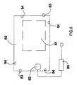
- Figure 6 shows a panel-form loudspeaker 80 having an in-board unobstructed region 81 extending throughout and beyond normal in-board preferential drive transducer locations, and a marginally located transducer 82.
- the region 81 may serve for display purposes directly, or represent something carried by the panel 80 without affecting acoustic performance, or something behind which the loudspeaker panel 80 passes, say in close spacing and/or transparent or translucent. Both of loudness and quality are readily enhanced, the former by additional drive transducers judiciously placed (not shown), and quality by localised edge clamping(s) 83 beneficially to control particular modal vibration points effectively as panel termination(s).
- the panel 80 is further indicated with localised resilient suspensions 84 located neutrally or even beneficially regarding achieved acoustic performance.
- High pass filtering 85 is preferred for input signals to drive transducer(s) 82, conveniently to limit to range of best reproduction, say not below 100Hz for A4-size or similar panels. Then, there should not be any problematic low-frequency panel/exciter vibration.
- acoustic performance it is advantageous in terms for acoustic performance to control acoustic impedance loading on the panel 80, say to be relatively low in the marginal or peripheral region, especially in the vicinity of the drive transducer(s) 82 where surface velocity tends to be high.
- Beneficial such control provision includes significant clearance to local planar members (say about 1 - 3 centimetre) and/or slots or other apertures in adjacent peripheral framing or support provision or grille elements.
- FIG. 7A, B A higher stiffness panel member is shown in the second column
- Figures 7A, B relate to the much lower stiffness panel member of the first column
- an intermediate stiffness panel member is shown in the third column.
- FIG. 7A An application for localised edge clamping is in relation to improving an unpromising transducer edge location, see bar charts Figures 7A, B showing right hand rather than left hand sides of the edge concerned as otherwise in the drawings.
- the cases concerned relate to the lower stiffness panel member, and are full clamping of three edges and seven point clamping, with a localised clamp varied along the same edge as the transducer means.
- useful improvement results at about the quarter length position from the corner more remote from the exciter - see reference bar at right hand side of Figure 7B for no clamping condition.
- the spread is greater for the full edge clamping case, see Figure 7A .
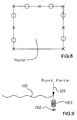
- the mechanical impedance (Zm) of a panel member determines the movement resulting for an applied point force, see 100, 101 in Figure 9 .
- An object associated with the panel with a mechanical impedance put very much less than, even approaching comparable to, the panel impedance will strongly offset panel motion where the object is located.
- Associating an exciting transducer of moving coil type with the panel is equivalent to connecting the panel to a grounded mass (the magnet cup of the transducer, see 102) via a spring (the voice coil suspension of the transducer, see 108).
- the impedance of such spring is too close to the panel impedance, it will in some part determine the panel motion at the transducer. In the limit of this spring wholly determining the point motion at the transducer, there would be no dependence of input power on exciter position.
- the transducer in part determines the impedance of the panel member, and smoothness of the output power is less dependent on the position of the transducer.
Landscapes
- Engineering & Computer Science (AREA)
- Multimedia (AREA)
- Physics & Mathematics (AREA)
- Acoustics & Sound (AREA)
- Signal Processing (AREA)
- Diaphragms For Electromechanical Transducers (AREA)
- Piezo-Electric Transducers For Audible Bands (AREA)
- Piezo-Electric Or Mechanical Vibrators, Or Delay Or Filter Circuits (AREA)
- Apparatuses For Generation Of Mechanical Vibrations (AREA)
- Soundproofing, Sound Blocking, And Sound Damping (AREA)
Applications Claiming Priority (7)
| Application Number | Priority Date | Filing Date | Title |
|---|---|---|---|
| GBGB9801057.2A GB9801057D0 (en) | 1998-01-20 | 1998-01-20 | Acoustic panels |
| GB9801057 | 1998-01-20 | ||
| GBGB9801054.9A GB9801054D0 (en) | 1998-01-20 | 1998-01-20 | Acoustic panels |
| GB9801054 | 1998-01-20 | ||
| GBGB9811100.8A GB9811100D0 (en) | 1998-05-23 | 1998-05-23 | Acoustic panels |
| GBGB9813293.9A GB9813293D0 (en) | 1998-06-20 | 1998-06-20 | Acoustic panels |
| EP99901055A EP1050190B1 (en) | 1998-01-20 | 1999-01-15 | Active acoustic devices comprising panel members |
Related Parent Applications (2)
| Application Number | Title | Priority Date | Filing Date |
|---|---|---|---|
| EP99901055.6 Division | 1999-01-15 | ||
| EP99901055A Division EP1050190B1 (en) | 1998-01-20 | 1999-01-15 | Active acoustic devices comprising panel members |
Publications (3)
| Publication Number | Publication Date |
|---|---|
| EP1414266A2 EP1414266A2 (en) | 2004-04-28 |
| EP1414266A3 EP1414266A3 (en) | 2006-08-16 |
| EP1414266B1 true EP1414266B1 (en) | 2008-02-13 |
Family
ID=27451742
Family Applications (2)
| Application Number | Title | Priority Date | Filing Date |
|---|---|---|---|
| EP04075008A Expired - Lifetime EP1414266B1 (en) | 1998-01-20 | 1999-01-15 | Active acoustic devices |
| EP99901055A Expired - Lifetime EP1050190B1 (en) | 1998-01-20 | 1999-01-15 | Active acoustic devices comprising panel members |
Family Applications After (1)
| Application Number | Title | Priority Date | Filing Date |
|---|---|---|---|
| EP99901055A Expired - Lifetime EP1050190B1 (en) | 1998-01-20 | 1999-01-15 | Active acoustic devices comprising panel members |
Country Status (22)
| Country | Link |
|---|---|
| EP (2) | EP1414266B1 (enExample) |
| JP (1) | JP4173283B2 (enExample) |
| KR (1) | KR100646191B1 (enExample) |
| CN (1) | CN1287766B (enExample) |
| AR (1) | AR014430A1 (enExample) |
| AT (1) | ATE280482T1 (enExample) |
| AU (1) | AU747693B2 (enExample) |
| BG (1) | BG104543A (enExample) |
| BR (1) | BR9907145A (enExample) |
| CA (1) | CA2318292A1 (enExample) |
| DE (2) | DE69921295T8 (enExample) |
| EA (1) | EA200000781A1 (enExample) |
| HU (1) | HUP0102858A3 (enExample) |
| IL (1) | IL136820A0 (enExample) |
| NO (1) | NO20003705L (enExample) |
| NZ (1) | NZ504133A (enExample) |
| PL (1) | PL341377A1 (enExample) |
| SK (1) | SK10822000A3 (enExample) |
| TR (1) | TR200002108T2 (enExample) |
| TW (1) | TW432889B (enExample) |
| WO (1) | WO1999037121A1 (enExample) |
| YU (1) | YU36800A (enExample) |
Families Citing this family (82)
| Publication number | Priority date | Publication date | Assignee | Title |
|---|---|---|---|---|
| AR019105A1 (es) * | 1998-04-28 | 2001-12-26 | New Transducers Ltd | Metodo para determinar el emplazamiento o emplazamientos ventajosos para posicionar un dispositivo transductor de ondas de flexion. |
| PL191378B1 (pl) | 1998-06-22 | 2006-05-31 | Slab Technology Ltd | Głośnik |
| DE69911961T2 (de) | 1998-07-03 | 2004-07-29 | New Transducers Ltd. | Plattenförmiger resonanter lautsprecher |
| JP2000092578A (ja) * | 1998-09-09 | 2000-03-31 | Fujitsu Ltd | スピーカ装置 |
| DE19917584A1 (de) * | 1999-04-19 | 2000-10-26 | Siemens Ag | Flächenlautsprecher und Verfahren zu dessen Betrieb |
| JP3512087B2 (ja) | 1999-06-15 | 2004-03-29 | 日本電気株式会社 | パネルスピーカ |
| JP3591578B2 (ja) | 1999-11-09 | 2004-11-24 | ヤマハ株式会社 | 音響放射体 |
| TW511391B (en) | 2000-01-24 | 2002-11-21 | New Transducers Ltd | Transducer |
| US7151837B2 (en) | 2000-01-27 | 2006-12-19 | New Transducers Limited | Loudspeaker |
| US6721436B1 (en) | 2000-03-29 | 2004-04-13 | Sound Advance Systems, Inc. | Remote edge-driven panel speaker |
| JP4683367B2 (ja) * | 2000-08-04 | 2011-05-18 | ヤマハ株式会社 | 線状加振装置及び該加振装置を備えたスピーカ |
| GB0019701D0 (en) * | 2000-08-11 | 2000-09-27 | New Transducers Ltd | Loudspeaker |
| GB0022913D0 (en) * | 2000-09-19 | 2000-11-01 | New Transducers Ltd | Loudspeaker |
| GB2369232B (en) | 2000-11-18 | 2005-01-12 | Talksign Ltd | Display signs |
| US20050084131A1 (en) * | 2001-05-11 | 2005-04-21 | Julian Fordham | Loudspeakers |
| FR2825882B1 (fr) * | 2001-06-12 | 2003-08-15 | Intelligent Vibrations Sa | Vitrage interactif avec fonctions microphones et haut-parleur |
| EP1274272A1 (en) * | 2001-06-19 | 2003-01-08 | Chao-Hsien Lin | The application of invisible speaker and the method for fabricating the same |
| EP1271998B1 (en) * | 2001-06-28 | 2008-04-16 | Matsushita Electric Industrial Co., Ltd. | Speaker system, mobile terminal device, and electronic device |
| DE10164509A1 (de) * | 2001-12-28 | 2003-07-17 | Webasto Vehicle Sys Int Gmbh | Lautsprechersystem für die Audioanlage eines Kraftfahrzeuges |
| US7548854B2 (en) | 2002-01-31 | 2009-06-16 | Awi Licensing Company | Architectural sound enhancement with pre-filtered masking sound |
| US6988339B2 (en) | 2002-02-06 | 2006-01-24 | Andersen Corporation | Specialty media window |
| US7426804B2 (en) | 2002-02-06 | 2008-09-23 | Andersen Corporation | Specialty display window |
| JP3886391B2 (ja) * | 2002-02-15 | 2007-02-28 | シャープ株式会社 | カード型装置、及び、それを備えた電子機器 |
| US6983819B2 (en) | 2002-04-02 | 2006-01-10 | Awi Licensing Company | Entertainment sound panels |
| EP1385354A1 (en) * | 2002-07-25 | 2004-01-28 | Kam, Tai-Yan | Transparent panel-form loudspeaker |
| EP1480489A3 (en) * | 2003-05-23 | 2009-07-01 | Alps Electric Co., Ltd. | Exciting device for producing sound |
| US20040240687A1 (en) * | 2003-05-30 | 2004-12-02 | Graetz Michael L. | Flat panel speaker |
| JP4196096B2 (ja) * | 2003-10-03 | 2008-12-17 | パナソニック株式会社 | スピーカモジュールおよびこれを用いた電子機器およびこのスピーカモジュールを用いた装置 |
| JP4196097B2 (ja) | 2003-10-06 | 2008-12-17 | パナソニック株式会社 | スピーカ、スピーカモジュールおよびこれを用いた電子機器 |
| GB0400323D0 (en) | 2004-01-08 | 2004-02-11 | New Transducers Ltd | Loudspeakers |
| GB0405475D0 (en) * | 2004-03-11 | 2004-04-21 | New Transducers Ltd | Loudspeakers |
| DE102004032223A1 (de) * | 2004-07-02 | 2006-01-19 | Siemens Ag | Audiovisuelle Anordnung |
| US10848118B2 (en) | 2004-08-10 | 2020-11-24 | Bongiovi Acoustics Llc | System and method for digital signal processing |
| US10158337B2 (en) | 2004-08-10 | 2018-12-18 | Bongiovi Acoustics Llc | System and method for digital signal processing |
| US11431312B2 (en) | 2004-08-10 | 2022-08-30 | Bongiovi Acoustics Llc | System and method for digital signal processing |
| US8284955B2 (en) | 2006-02-07 | 2012-10-09 | Bongiovi Acoustics Llc | System and method for digital signal processing |
| JP4700323B2 (ja) * | 2004-10-28 | 2011-06-15 | ホシデン株式会社 | フラットパネルスピーカ |
| JP4072542B2 (ja) * | 2005-03-14 | 2008-04-09 | Necアクセステクニカ株式会社 | スピーカ一体型ディスプレイ |
| US8180065B2 (en) | 2005-10-13 | 2012-05-15 | Magna Mirrors Of America, Inc. | Acoustical window assembly for vehicle |
| RU2436747C2 (ru) * | 2005-12-07 | 2011-12-20 | Агк Гласс Юроп | Звукогенерирующее остекление |
| US8389120B2 (en) | 2005-12-07 | 2013-03-05 | Agc Glass Europe | Sound-generating glazing |
| US10848867B2 (en) | 2006-02-07 | 2020-11-24 | Bongiovi Acoustics Llc | System and method for digital signal processing |
| US9615189B2 (en) | 2014-08-08 | 2017-04-04 | Bongiovi Acoustics Llc | Artificial ear apparatus and associated methods for generating a head related audio transfer function |
| US10069471B2 (en) | 2006-02-07 | 2018-09-04 | Bongiovi Acoustics Llc | System and method for digital signal processing |
| US11202161B2 (en) | 2006-02-07 | 2021-12-14 | Bongiovi Acoustics Llc | System, method, and apparatus for generating and digitally processing a head related audio transfer function |
| US10701505B2 (en) | 2006-02-07 | 2020-06-30 | Bongiovi Acoustics Llc. | System, method, and apparatus for generating and digitally processing a head related audio transfer function |
| DE102006056394B4 (de) * | 2006-11-29 | 2010-05-20 | Siemens Ag | Beleuchtungseinrichtung |
| GB2471474B (en) * | 2009-06-30 | 2014-11-19 | New Transducers Ltd | Actuator |
| JP5527878B2 (ja) * | 2009-07-30 | 2014-06-25 | トムソン ライセンシング | 表示装置及び音声出力装置 |
| FR2955226B1 (fr) * | 2010-01-08 | 2011-12-30 | Commissariat Energie Atomique | Dispositif de detection d'ondes acoustiques et systeme de localisation d'une source d'ondes acoustiques |
| CN102474691B (zh) * | 2010-04-15 | 2016-03-23 | 松下知识产权经营株式会社 | 压电式扬声器 |
| JP2012105021A (ja) * | 2010-11-09 | 2012-05-31 | Sony Corp | スピーカー装置 |
| US8983098B2 (en) * | 2012-08-14 | 2015-03-17 | Turtle Beach Corporation | Substantially planate parametric emitter and associated methods |
| US20150381024A9 (en) * | 2013-03-14 | 2015-12-31 | Lewis Athanas | Linear Loudspeaker Motor |
| US9883318B2 (en) | 2013-06-12 | 2018-01-30 | Bongiovi Acoustics Llc | System and method for stereo field enhancement in two-channel audio systems |
| US9264004B2 (en) | 2013-06-12 | 2016-02-16 | Bongiovi Acoustics Llc | System and method for narrow bandwidth digital signal processing |
| US9906858B2 (en) | 2013-10-22 | 2018-02-27 | Bongiovi Acoustics Llc | System and method for digital signal processing |
| US9615813B2 (en) | 2014-04-16 | 2017-04-11 | Bongiovi Acoustics Llc. | Device for wide-band auscultation |
| US10639000B2 (en) | 2014-04-16 | 2020-05-05 | Bongiovi Acoustics Llc | Device for wide-band auscultation |
| US10820883B2 (en) | 2014-04-16 | 2020-11-03 | Bongiovi Acoustics Llc | Noise reduction assembly for auscultation of a body |
| US9564146B2 (en) | 2014-08-01 | 2017-02-07 | Bongiovi Acoustics Llc | System and method for digital signal processing in deep diving environment |
| US9660596B2 (en) * | 2015-01-23 | 2017-05-23 | Tectonic Audio Labs | Audio transducer stabilization system and method |
| US9638672B2 (en) | 2015-03-06 | 2017-05-02 | Bongiovi Acoustics Llc | System and method for acquiring acoustic information from a resonating body |
| CN104789473B (zh) * | 2015-05-18 | 2018-02-09 | 宁波大学 | 一种用于微藻冻存的非渗透保护剂 |
| US9906867B2 (en) | 2015-11-16 | 2018-02-27 | Bongiovi Acoustics Llc | Surface acoustic transducer |
| US9621994B1 (en) | 2015-11-16 | 2017-04-11 | Bongiovi Acoustics Llc | Surface acoustic transducer |
| EP3565275B1 (en) | 2016-12-27 | 2023-07-19 | Sony Group Corporation | Display device |
| US11115740B2 (en) | 2016-12-27 | 2021-09-07 | Sony Corporation | Flat panel speaker and display unit |
| WO2019070005A1 (ja) * | 2017-10-04 | 2019-04-11 | Agc株式会社 | ディスプレイ装置およびテレビジョン装置 |
| JP7322712B2 (ja) | 2017-12-28 | 2023-08-08 | ソニーグループ株式会社 | 表示装置 |
| US11579833B2 (en) | 2017-12-28 | 2023-02-14 | Sony Corporation | Display apparatus and signal generation apparatus |
| CN108510436B (zh) * | 2018-03-28 | 2020-09-15 | 清华大学 | 一种冷冻电镜三维重构中重构参数搜索方法和系统 |
| US11211043B2 (en) | 2018-04-11 | 2021-12-28 | Bongiovi Acoustics Llc | Audio enhanced hearing protection system |
| US10959035B2 (en) | 2018-08-02 | 2021-03-23 | Bongiovi Acoustics Llc | System, method, and apparatus for generating and digitally processing a head related audio transfer function |
| CN110913319B (zh) * | 2018-09-18 | 2021-10-01 | 乐金显示有限公司 | 显示设备 |
| US11438704B2 (en) * | 2018-10-13 | 2022-09-06 | The University Of Rochester | Method, system and devices for selective modal control for vibrating structures |
| US10782731B1 (en) * | 2019-02-28 | 2020-09-22 | Google Llc | Modal frequency shifting for loudspeaker devices |
| RU2743892C1 (ru) * | 2020-06-16 | 2021-03-01 | Сотис АГ | Плоский громкоговоритель |
| US12352102B2 (en) | 2020-08-07 | 2025-07-08 | Cardinal Cg Company | Aerogel glazing adhesion and IG unit technology |
| EP4323318A1 (en) | 2021-04-15 | 2024-02-21 | Cardinal CG Company | Flexible aerogel, flexible glass technology |
| US20230286810A1 (en) | 2022-03-09 | 2023-09-14 | Cardinal Cg Company | Silica wet gel and aerogel |
| AT525365B1 (de) | 2022-05-25 | 2023-03-15 | Cale3D Prime Gmbh | Elektroakustischer Wandler |
Family Cites Families (5)
| Publication number | Priority date | Publication date | Assignee | Title |
|---|---|---|---|---|
| US3247925A (en) * | 1962-03-08 | 1966-04-26 | Lord Corp | Loudspeaker |
| DE1132593B (de) * | 1965-04-05 | 1962-07-05 | Bolt Beranek & Newman | Akustisch wirksame Platte, insbesondere zur Ankopplung an einen elektroakustischen Wandler |
| JPS6161598A (ja) * | 1984-09-03 | 1986-03-29 | Matsushita Electric Ind Co Ltd | 音響装置 |
| WO1992003024A1 (en) * | 1990-08-04 | 1992-02-20 | The Secretary Of State For Defence In Her Britannic Majesty's Government Of The United Kingdom Of Great Britain And Northern Ireland | Panel-form loudspeaker |
| UA51671C2 (uk) * | 1995-09-02 | 2002-12-16 | Нью Транзд'Юсез Лімітед | Акустичний пристрій |
-
1999
- 1999-01-15 HU HU0102858A patent/HUP0102858A3/hu unknown
- 1999-01-15 EP EP04075008A patent/EP1414266B1/en not_active Expired - Lifetime
- 1999-01-15 PL PL99341377A patent/PL341377A1/xx unknown
- 1999-01-15 TR TR2000/02108T patent/TR200002108T2/xx unknown
- 1999-01-15 IL IL13682099A patent/IL136820A0/xx unknown
- 1999-01-15 EA EA200000781A patent/EA200000781A1/ru unknown
- 1999-01-15 WO PCT/GB1999/000143 patent/WO1999037121A1/en not_active Ceased
- 1999-01-15 YU YU36800A patent/YU36800A/sh unknown
- 1999-01-15 AT AT99901055T patent/ATE280482T1/de not_active IP Right Cessation
- 1999-01-15 EP EP99901055A patent/EP1050190B1/en not_active Expired - Lifetime
- 1999-01-15 JP JP2000540693A patent/JP4173283B2/ja not_active Expired - Lifetime
- 1999-01-15 BR BR9907145-2A patent/BR9907145A/pt not_active IP Right Cessation
- 1999-01-15 NZ NZ504133A patent/NZ504133A/en unknown
- 1999-01-15 CA CA002318292A patent/CA2318292A1/en not_active Abandoned
- 1999-01-15 SK SK1082-2000A patent/SK10822000A3/sk unknown
- 1999-01-15 KR KR1020007007968A patent/KR100646191B1/ko not_active Expired - Fee Related
- 1999-01-15 DE DE69921295T patent/DE69921295T8/de active Active
- 1999-01-15 CN CN998019070A patent/CN1287766B/zh not_active Expired - Lifetime
- 1999-01-15 AU AU20681/99A patent/AU747693B2/en not_active Ceased
- 1999-01-15 DE DE69839134T patent/DE69839134T2/de not_active Expired - Lifetime
- 1999-01-19 AR ARP990100197A patent/AR014430A1/es not_active Application Discontinuation
- 1999-01-22 TW TW088101010A patent/TW432889B/zh not_active IP Right Cessation
-
2000
- 2000-06-16 BG BG104543A patent/BG104543A/bg unknown
- 2000-07-19 NO NO20003705A patent/NO20003705L/no not_active Application Discontinuation
Also Published As
Similar Documents
| Publication | Publication Date | Title |
|---|---|---|
| EP1414266B1 (en) | Active acoustic devices | |
| US6522760B2 (en) | Active acoustic devices | |
| AU754818B2 (en) | Resonant panel-form loudspeaker | |
| US6332029B1 (en) | Acoustic device | |
| EP0847661B2 (en) | Acoustic device | |
| CN1195456A (zh) | 带有扬声器的布告牌 | |
| CZ57698A3 (cs) | Reproduktor obsahující panelové akustické vyzařující prvky | |
| AU2002300608B2 (en) | Active Acoustic Devices Comprising Panel Members | |
| HK1029247B (en) | Active acoustic devices comprising panel members | |
| MXPA00007086A (en) | Active acoustic devices comprising panel members | |
| CZ20002588A3 (cs) | Aktivní akustická zařízení obsahující panelové členy | |
| HK1008636B (en) | Acoustic device |
Legal Events
| Date | Code | Title | Description |
|---|---|---|---|
| PUAI | Public reference made under article 153(3) epc to a published international application that has entered the european phase |
Free format text: ORIGINAL CODE: 0009012 |
|
| AC | Divisional application: reference to earlier application |
Ref document number: 1050190 Country of ref document: EP Kind code of ref document: P |
|
| AK | Designated contracting states |
Kind code of ref document: A2 Designated state(s): AT BE CH DE DK ES FI FR GB IE IT LI NL PT SE |
|
| RAP1 | Party data changed (applicant data changed or rights of an application transferred) |
Owner name: NEW TRANSDUCERS LIMITED |
|
| PUAL | Search report despatched |
Free format text: ORIGINAL CODE: 0009013 |
|
| AK | Designated contracting states |
Kind code of ref document: A3 Designated state(s): AT BE CH DE DK ES FI FR GB IE IT LI NL PT SE |
|
| RIC1 | Information provided on ipc code assigned before grant |
Ipc: H04R 7/10 20060101ALI20060711BHEP Ipc: H04R 7/00 20060101ALI20060711BHEP Ipc: H04R 7/06 20060101AFI20060711BHEP |
|
| 17P | Request for examination filed |
Effective date: 20061026 |
|
| 17Q | First examination report despatched |
Effective date: 20061201 |
|
| AKX | Designation fees paid |
Designated state(s): DE FR GB NL |
|
| GRAP | Despatch of communication of intention to grant a patent |
Free format text: ORIGINAL CODE: EPIDOSNIGR1 |
|
| GRAS | Grant fee paid |
Free format text: ORIGINAL CODE: EPIDOSNIGR3 |
|
| GRAA | (expected) grant |
Free format text: ORIGINAL CODE: 0009210 |
|
| AC | Divisional application: reference to earlier application |
Ref document number: 1050190 Country of ref document: EP Kind code of ref document: P |
|
| AK | Designated contracting states |
Kind code of ref document: B1 Designated state(s): DE FR GB NL |
|
| REG | Reference to a national code |
Ref country code: GB Ref legal event code: FG4D |
|
| REF | Corresponds to: |
Ref document number: 69839134 Country of ref document: DE Date of ref document: 20080327 Kind code of ref document: P |
|
| ET | Fr: translation filed | ||
| PLBE | No opposition filed within time limit |
Free format text: ORIGINAL CODE: 0009261 |
|
| STAA | Information on the status of an ep patent application or granted ep patent |
Free format text: STATUS: NO OPPOSITION FILED WITHIN TIME LIMIT |
|
| 26N | No opposition filed |
Effective date: 20081114 |
|
| PGFP | Annual fee paid to national office [announced via postgrant information from national office to epo] |
Ref country code: FR Payment date: 20120206 Year of fee payment: 14 |
|
| PGFP | Annual fee paid to national office [announced via postgrant information from national office to epo] |
Ref country code: NL Payment date: 20120125 Year of fee payment: 14 |
|
| REG | Reference to a national code |
Ref country code: NL Ref legal event code: V1 Effective date: 20130801 |
|
| REG | Reference to a national code |
Ref country code: FR Ref legal event code: ST Effective date: 20130930 |
|
| PG25 | Lapsed in a contracting state [announced via postgrant information from national office to epo] |
Ref country code: NL Free format text: LAPSE BECAUSE OF NON-PAYMENT OF DUE FEES Effective date: 20130801 |
|
| PG25 | Lapsed in a contracting state [announced via postgrant information from national office to epo] |
Ref country code: FR Free format text: LAPSE BECAUSE OF NON-PAYMENT OF DUE FEES Effective date: 20130131 |
|
| PGFP | Annual fee paid to national office [announced via postgrant information from national office to epo] |
Ref country code: DE Payment date: 20140130 Year of fee payment: 16 |
|
| REG | Reference to a national code |
Ref country code: DE Ref legal event code: R119 Ref document number: 69839134 Country of ref document: DE |
|
| PG25 | Lapsed in a contracting state [announced via postgrant information from national office to epo] |
Ref country code: DE Free format text: LAPSE BECAUSE OF NON-PAYMENT OF DUE FEES Effective date: 20150801 |
|
| PGFP | Annual fee paid to national office [announced via postgrant information from national office to epo] |
Ref country code: GB Payment date: 20180129 Year of fee payment: 20 |
|
| REG | Reference to a national code |
Ref country code: GB Ref legal event code: PE20 Expiry date: 20190114 |
|
| PG25 | Lapsed in a contracting state [announced via postgrant information from national office to epo] |
Ref country code: GB Free format text: LAPSE BECAUSE OF EXPIRATION OF PROTECTION Effective date: 20190114 |
|
| P01 | Opt-out of the competence of the unified patent court (upc) registered |
Effective date: 20230520 |