EP1414137A1 - Procede de fabrication d'un moteur et appareil d'insertion d'un enroulement - Google Patents
Procede de fabrication d'un moteur et appareil d'insertion d'un enroulement Download PDFInfo
- Publication number
- EP1414137A1 EP1414137A1 EP02751809A EP02751809A EP1414137A1 EP 1414137 A1 EP1414137 A1 EP 1414137A1 EP 02751809 A EP02751809 A EP 02751809A EP 02751809 A EP02751809 A EP 02751809A EP 1414137 A1 EP1414137 A1 EP 1414137A1
- Authority
- EP
- European Patent Office
- Prior art keywords
- coil
- unipolar
- motor
- spool
- motor core
- Prior art date
- Legal status (The legal status is an assumption and is not a legal conclusion. Google has not performed a legal analysis and makes no representation as to the accuracy of the status listed.)
- Withdrawn
Links
Images


Classifications
-
- H—ELECTRICITY
- H02—GENERATION; CONVERSION OR DISTRIBUTION OF ELECTRIC POWER
- H02K—DYNAMO-ELECTRIC MACHINES
- H02K15/00—Methods or apparatus specially adapted for manufacturing, assembling, maintaining or repairing of dynamo-electric machines
- H02K15/0025—Shaping or compacting conductors or winding heads after the installation of the winding in the core or machine ; Applying fastening means on winding heads
- H02K15/0037—Shaping or compacting winding heads
-
- H—ELECTRICITY
- H02—GENERATION; CONVERSION OR DISTRIBUTION OF ELECTRIC POWER
- H02K—DYNAMO-ELECTRIC MACHINES
- H02K15/00—Methods or apparatus specially adapted for manufacturing, assembling, maintaining or repairing of dynamo-electric machines
- H02K15/06—Embedding prefabricated windings in machines
-
- H—ELECTRICITY
- H02—GENERATION; CONVERSION OR DISTRIBUTION OF ELECTRIC POWER
- H02K—DYNAMO-ELECTRIC MACHINES
- H02K15/00—Methods or apparatus specially adapted for manufacturing, assembling, maintaining or repairing of dynamo-electric machines
- H02K15/04—Methods or apparatus specially adapted for manufacturing, assembling, maintaining or repairing of dynamo-electric machines of windings, prior to mounting into machines
- H02K15/0435—Wound windings
- H02K15/0442—Loop windings
-
- H—ELECTRICITY
- H02—GENERATION; CONVERSION OR DISTRIBUTION OF ELECTRIC POWER
- H02K—DYNAMO-ELECTRIC MACHINES
- H02K15/00—Methods or apparatus specially adapted for manufacturing, assembling, maintaining or repairing of dynamo-electric machines
- H02K15/06—Embedding prefabricated windings in machines
- H02K15/062—Windings in slots; salient pole windings
- H02K15/065—Windings consisting of complete sections, e.g. coils, waves
- H02K15/066—Windings consisting of complete sections, e.g. coils, waves inserted perpendicularly to the axis of the slots or inter-polar channels
-
- Y—GENERAL TAGGING OF NEW TECHNOLOGICAL DEVELOPMENTS; GENERAL TAGGING OF CROSS-SECTIONAL TECHNOLOGIES SPANNING OVER SEVERAL SECTIONS OF THE IPC; TECHNICAL SUBJECTS COVERED BY FORMER USPC CROSS-REFERENCE ART COLLECTIONS [XRACs] AND DIGESTS
- Y10—TECHNICAL SUBJECTS COVERED BY FORMER USPC
- Y10T—TECHNICAL SUBJECTS COVERED BY FORMER US CLASSIFICATION
- Y10T29/00—Metal working
- Y10T29/49—Method of mechanical manufacture
- Y10T29/49002—Electrical device making
- Y10T29/49009—Dynamoelectric machine
- Y10T29/49012—Rotor
-
- Y—GENERAL TAGGING OF NEW TECHNOLOGICAL DEVELOPMENTS; GENERAL TAGGING OF CROSS-SECTIONAL TECHNOLOGIES SPANNING OVER SEVERAL SECTIONS OF THE IPC; TECHNICAL SUBJECTS COVERED BY FORMER USPC CROSS-REFERENCE ART COLLECTIONS [XRACs] AND DIGESTS
- Y10—TECHNICAL SUBJECTS COVERED BY FORMER USPC
- Y10T—TECHNICAL SUBJECTS COVERED BY FORMER US CLASSIFICATION
- Y10T29/00—Metal working
- Y10T29/49—Method of mechanical manufacture
- Y10T29/49002—Electrical device making
- Y10T29/4902—Electromagnet, transformer or inductor
- Y10T29/49071—Electromagnet, transformer or inductor by winding or coiling
-
- Y—GENERAL TAGGING OF NEW TECHNOLOGICAL DEVELOPMENTS; GENERAL TAGGING OF CROSS-SECTIONAL TECHNOLOGIES SPANNING OVER SEVERAL SECTIONS OF THE IPC; TECHNICAL SUBJECTS COVERED BY FORMER USPC CROSS-REFERENCE ART COLLECTIONS [XRACs] AND DIGESTS
- Y10—TECHNICAL SUBJECTS COVERED BY FORMER USPC
- Y10T—TECHNICAL SUBJECTS COVERED BY FORMER US CLASSIFICATION
- Y10T29/00—Metal working
- Y10T29/49—Method of mechanical manufacture
- Y10T29/49002—Electrical device making
- Y10T29/4902—Electromagnet, transformer or inductor
- Y10T29/49073—Electromagnet, transformer or inductor by assembling coil and core
-
- Y—GENERAL TAGGING OF NEW TECHNOLOGICAL DEVELOPMENTS; GENERAL TAGGING OF CROSS-SECTIONAL TECHNOLOGIES SPANNING OVER SEVERAL SECTIONS OF THE IPC; TECHNICAL SUBJECTS COVERED BY FORMER USPC CROSS-REFERENCE ART COLLECTIONS [XRACs] AND DIGESTS
- Y10—TECHNICAL SUBJECTS COVERED BY FORMER USPC
- Y10T—TECHNICAL SUBJECTS COVERED BY FORMER US CLASSIFICATION
- Y10T29/00—Metal working
- Y10T29/53—Means to assemble or disassemble
- Y10T29/5313—Means to assemble electrical device
- Y10T29/53143—Motor or generator
- Y10T29/53152—Means to position insulation
-
- Y—GENERAL TAGGING OF NEW TECHNOLOGICAL DEVELOPMENTS; GENERAL TAGGING OF CROSS-SECTIONAL TECHNOLOGIES SPANNING OVER SEVERAL SECTIONS OF THE IPC; TECHNICAL SUBJECTS COVERED BY FORMER USPC CROSS-REFERENCE ART COLLECTIONS [XRACs] AND DIGESTS
- Y10—TECHNICAL SUBJECTS COVERED BY FORMER USPC
- Y10T—TECHNICAL SUBJECTS COVERED BY FORMER US CLASSIFICATION
- Y10T29/00—Metal working
- Y10T29/53—Means to assemble or disassemble
- Y10T29/5313—Means to assemble electrical device
- Y10T29/53143—Motor or generator
- Y10T29/53157—Means to stake wire to commutator or armature
-
- Y—GENERAL TAGGING OF NEW TECHNOLOGICAL DEVELOPMENTS; GENERAL TAGGING OF CROSS-SECTIONAL TECHNOLOGIES SPANNING OVER SEVERAL SECTIONS OF THE IPC; TECHNICAL SUBJECTS COVERED BY FORMER USPC CROSS-REFERENCE ART COLLECTIONS [XRACs] AND DIGESTS
- Y10—TECHNICAL SUBJECTS COVERED BY FORMER USPC
- Y10T—TECHNICAL SUBJECTS COVERED BY FORMER US CLASSIFICATION
- Y10T29/00—Metal working
- Y10T29/53—Means to assemble or disassemble
- Y10T29/5313—Means to assemble electrical device
- Y10T29/53143—Motor or generator
- Y10T29/53161—Motor or generator including deforming means
Definitions
- the present invention relates to a motor manufacturing method, and more particularly to an insertion method of a coil into a motor core.
- Conventional coil insertion methods mainly consist of so-called inserter methods such as disclosed in, for example, Japanese Patent Laid-Open Publication No. 2000-125522, Japanese Patent Laid-Open Publication No. 2000-116078, Japanese Patent Laid-Open Publication No. 9-322492 and the like.
- a ring-shaped stator core 1 is placed horizontally and a coil 8 is also placed substantially horizontally downward of an axial direction thereof.
- a jig (not shown) is raised from below the coil 8 into the inside of the stator core 1 and an inner end 81 of the coil 8 is hooked by the jig and moved upward. Consequently, the coil 8 is moved to gradually change from a horizontal state to a vertical state such that it rubs the inner peripheral surface of the stator core 1, and is inserted into slots 10 of the stator core 1.
- the coil 8 is inserted into the slots 10 of the stator core 1 while changing the state of the coil 8 as described above, therefore, a state occurs in which the coil 8 is inserted obliquely en route.
- the dimension of the coil 8 needs to have at least an allowance of a length L0 in a vertical direction thereof.
- the present invention has been achieved in view of the foregoing problems, and it is an object of the present invention to provide a motor manufacturing method in which the amount of protrusion of the coil from the stator core can be reduced, and the motor length in the axial direction can be shortened.
- a motor manufacturing method has a stator formed by inserting coils into slots provided in an inner peripheral surface of a ring-shaped motor core, the motor manufacturing method characterized by including:
- each unipolar coil is disposed such that the coil inserting portion is substantially parallel to inner peripheral opening portion in the respective slots. Then, the unipolar coil is moved substantially linearly toward the motor core. Finally, the coil inserting portion of the unipolar coil is inserted into the slot.
- the coil in the coil insertion step, the coil can be inserted by its linear moving without greatly changing the orientation of the unipolar coil. Since the so-called linear inserting method can be carried out, the vertical length of the unipolar coil does not need to be made longer than required. Thus, the lengths of the coil inserting portion and the coil end portion of the unipolar coil can be set to optimum lengths for a state in which they are mounted on the motor core. Moreover, the length of a part in the axial direction formed by mounting the coil onto the motor core, and the entire motor length in the axial direction can be shortened.
- a motor manufacturing method has a stator formed by inserting coils into slots provided in an inner peripheral surface of a ring-shaped motor core, the motor manufacturing method characterized by including:
- a motor manufacturing method has a stator formed by inserting coils into slots provided in an inner peripheral surface of a ring-shaped motor core, the motor manufacturing method characterized by including:
- a motor manufacturing method has a stator formed by inserting coils into slots provided in an inner peripheral surface of a ring-shaped motor core, the motor manufacturing method characterized by including:
- the coil insertion step enables the coil to be inserted by its linear moving without greatly changing the orientation of the unipolar coil. Since the so-called linear inserting method can be carried out, the vertical length of the unipolar coil does not need to be made longer than required. Thus, the length of the coil inserting portion and the coil end portion of the unipolar coil can be set to optimum lengths for a state in which they are mounted on the motor core. Moreover, the length of a part in the axial direction formed by mounting the coil onto the motor core, and the entire motor length in the axial direction can be shortened.
- a coil insertion apparatus is provided using a coil holding mechanism provided with a coil holding groove at a position opposing a motor core, inserting a coil inserting portion of a unipolar coil inserted into the coil holding groove so the coil holding mechanism holds the unipolar coil, in order to insert the unipolar coil into a slot in the motor core from the coil holding mechanism, in a state where the motor core that is ring-shaped is disposed on an outer periphery side of the coil holding mechanism, the coil insertion apparatus characterized by including:
- the aforementioned unipolar coil in the coil insertion step it is preferable for moving of the aforementioned unipolar coil in the coil insertion step to be carried out with an angle formed between the coil inserting portion and the axial direction of the motor core maintained in a state less than 5 degrees. If the angle between the coil inserting portion and the axial direction of the motor core exceeds 5 degrees, there is concern that an effect reducing the length of the coil end portion may be lowered.
- the coil insertion step preferably, only the unipolar coil is inserted into the slots in the motor core. Namely, in a state where the coil is wound around a bobbin or the like, it is preferable for only the coil to be moved to the motor core, without moving the entire bobbin. Consequently, a distance between the motor core and each coil (unipolar coil) can be reduced, which is advantageous for the formation of a highly efficient magnetic circuit.
- the unipolar coil in the coil insertion step, preferably, is held by a coil holding mechanism during or after the coil formation step so that the coil inserting portion opposes inner peripheral opening portions of respective slots, and the unipolar coil is disposed such that it is substantially parallel to the axial direction of the motor core. Then, the coil inserting portion is moved substantially linearly toward a motor core so as to remove the unipolar coil from the coil holding mechanism. In this case as well, it is easy to mount only the unipolar coil on the motor core without the bobbin.
- the motor has the ring-shaped motor core provided with a plurality of slots in its inner peripheral surface and coil groups of plural phases; the coil group of each phase is constituted by a plurality of unipolar coils composing a single pole, and each unipolar coil is inserted in and disposed on the motor core such that it straddles two respective slots; and further, the unipolar coils belonging to coil groups of different phases mutually overlap on portions of the respective coil end portions in a state mounted on the motor core so as to form a distribution winding type motor.
- a linear inserting method is extremely effective for constructing the coil end portion, which is a protruding portion of the coil, in a compact form.
- the aforementioned motor core prefferably be a stator core.
- the stator core and the rotor core are available as motor cores; however, particularly in the case of the stator core, the demand for making the length in the axial direction compact is strong, and for which the operation and effect of the present invention are extremely effective.
- the coil insertion step uses a magazine as the coil holding mechanism having a disc shape capable of being disposed on an inner side of an inner peripheral surface of the motor core, which is provided with coil holding grooves positioned opposing the slot of the motor core on an outer peripheral surface thereof, inserts the coil inserting portions of a plurality of the unipolar coils into the coil holding grooves so the coils are held by the magazine, disposes the magazine in an inner portion of the motor core such that the coil holding groove of the magazine opposes the slot of the motor core, and moves all the unipolar coils from the coil holding grooves to the slots in the motor core by contacting the coil inserting mechanism with all the unipolar coils on the magazine, and advancing a contact portion thereof in a direction from a center of the magazine toward an outer periphery.
- the coil is inserted into the coil holding groove in the magazine.
- the coil holding groove is provided on the outer peripheral surface of the magazine.
- an apparatus having a flexible structure not restricted by space can be used and a flexible operation method can be adopted.
- the mounting of the coil into the coil holding groove in the magazine can be carried out with relative ease.
- the coil inserting mechanism is moved inward to contact the coil, and moved outward. Consequently, the coil held by the coil holding groove in the magazine is pushed linearly by the coil inserting mechanism so that it is pressed into an opposing slot in the motor core without any change in orientation. Namely, moving of the coil inserting mechanism enables linear motion of the coil to be executed easily.
- the coil inserting mechanism is composed of insertion blades capable of being inserted into the coil holding grooves in the magazine, and the coil inserting portion is moved from the coil holding groove to the slot in the motor core by inserting the insertion blade into the coil holding groove and advancing from the center toward the outer periphery.
- insertion blade when the coil is mounted on the magazine, a gap remains between the bottom portion of the coil holding groove and the coil. Consequently, the insertion blade can be disposed within the coil holding groove. Then, by inserting the insertion blade into the coil holding groove, the insertion blade can come into contact with the coil inserting portion located in the coil holding groove, so that stable moving of the coil can be realized. Further, insertion timing for inserting the insertion blade into the coil holding groove may be at the same time the magazine is disposed within the motor core, or at a period before or after that.
- the insertion blade is structured to be inserted from either the front or rear surface side of the magazine. Consequently, the insertion blade moving mechanism can be obtained easily.
- the coil inserting mechanism is composed of a pair of divided insertion blades capable of being inserted from respective front and rear surface sides of the magazine into the coil holding grooves, and the pair of divided insertion blades are inserted into the respective coil holding grooves from the front and rear surface sides of the magazine so that they make contact with the coil inserting portion, and by advancing that contact portion from the center to the outer periphery, the coil inserting portion is moved from the coil holding groove into the slots in the motor core.
- the pair of divided insertion blades inserted into the coil holding groove from the front and rear surface sides of the magazine can be moved from the center to the outer periphery, or as shown in an embodiment described below, it is possible to move the coil linearly by only vertically inserting the pair of divided insertion blades having a tapered portion.
- the coil inserting mechanism is composed of a pair of divided insertion hooks separated on the front and rear surface sides of the magazine, and makes contact with the respective coil end portions projected to the front and rear surface sides of the magazine; the pair of divided insertion hooks are advanced from the center of the magazine toward the outer periphery so as to move the coil inserting portion from the coil holding groove into the slot in the motor core.
- the coil inserting mechanism it is not necessary for the coil inserting mechanism to be inserted into the coil holding groove, and the coil can be supported from the front and rear surface sides of the magazine easier and with more stability.
- a preliminary formation step for pressing and deforming the coil end portion by advancing a preliminary forming mechanism disposed between adjacent coil holding grooves from the center of the magazine toward the outer periphery at the same time or after the coil inserting portion is moved from the coil holding groove into the slot is executed.
- the preliminary formation step in which the coil end portion that is a protruding portion from the coil is pushed outward and deformed each time the coil is mounted on the motor core can be carried out easily. Consequently, the coil end portion approaches the surface of the motor core so that the length in the axial direction of the coil end portion can be further reduced.
- the apparatus and the step can be simplified.
- a preliminary forming groove is provided in the magazine in line with the coil holding groove, and as the preliminary forming mechanism, a preliminary formation blade capable of being inserted into the preliminary forming groove is employed in the preliminary formation step executed by inserting the preliminary formation blade into the preliminary forming groove and advancing it from the center toward the outer periphery.
- the apparatus structure can be obtained easily by the combination of the preliminary forming groove and the preliminary formation blade.
- the preliminary forming mechanism is composed of a pair of divided preliminary formation blades separated on the front and rear surface sides of the magazine, and the preliminary formation step is executed by advancing the pair of divided preliminary formation blades from the center of the magazine to the outer periphery on the front and rear surface sides.
- the preliminary formation can be stably executed from the front and rear sides of the coil.
- the coil inserting mechanism is composed of a pair of divided insertion blades separated on the front and rear surface sides of the magazine, and structured such that the divided insertion blades interlock with the divided preliminary formation blades.
- the coil inserting mechanism and the preliminary forming mechanism are divided on both front and rear surface sides of the magazine, it is preferable for the mechanisms present on the same surface side to be linked such that they interlock with each other. Consequently, the moving mechanisms for the coil inserting mechanism and the preliminary forming mechanism can be integrated, thereby enabling simplification of the apparatus structure.
- a main formation step that arranges the coil end portion by pressing formers, which have a forming face for arranging the coil end portion into a desired shape, against the motor core is executed.
- the entire coil subjected to the preliminary forming can be finally formed into a desired shape by only pressing the former onto the motor core.
- the main formation step can be executed easily. Since the coil end portion protruding from the motor core can be formed so as to be nearer the motor core with this main formation step, the dimension in the axial direction can be further reduced.
- the former is provided with a notch portion for preventing interference between the coil inserting mechanism and the preliminary forming mechanism, and the former is pressed against the motor core while maintaining a state in which the coil inserting mechanism and the preliminary forming mechanism are advanced.
- the coil can be fixed during the coil main formation step, so that the main formation step can be stably executed. Further, since the main formation step can be conducted continuously after the preliminary formation step is completed, the manufacturing process can be further streamlined.
- the motor is a 3-phase DC brushless motor, and in the coil insertion step, unipolar coils corresponding to a phase are simultaneously inserted into the slots in the motor core.
- coils corresponding to a phase can all be handled at one time using the magazine.
- all three phases can be accommodated so that the insertion operation of the coils into the motor core can be completed through repeating the operation three times.
- the winding jig for use in the coil formation step can be used.
- the coil formation step can use a winding jig having a base holder and a plurality of spools provided radially on an outer peripheral surface of the base holder, in which spools are disposed retractably with respect to the base holder, and include a spool projection step for advancing such that one spool among the plurality of spools projects more than other spools; a winding step for supplying wire to the projected spool from a single direction, and forms a unipolar coil by rotating the entire winding jig around an axis of the spool to wind the wire around the spool; a spool retraction step for retracting the spool on which the unipolar coil is formed, wherein the spool projection step, the winding step, and the spool retraction step are sequentially executed repeatedly for adjacent spools, with a rotation direction of the winding jig is sequentially reversed in the winding step; and the winding jig
- the coil is formed with the winding jig having a plurality of spools provided radially.
- this winding jig is disposed in an inner portion of the motor core.
- the spools possessed by the winding jig are disposed radially as described above, when the winding jig is disposed within the ring-shaped motor core, each unipolar coil can easily be made to oppose an insertion slot.
- the unipolar coil can be moved directly from the spool into the slot in the motor core, without transferring it from the winding jig to another transfer device or the like.
- the winding jig with the unique structure having the base holder and the spool is used.
- the spool projection step, the winding step, and the spool retraction step are conducted for each spool in that order.
- the winding step is conducted by rotating the entire winding jig around the axis of the projected spool.
- wire can be supplied from a single direction as described above, thereby eliminating the necessity of conventionally turning the wire itself.
- the unipolar coil can be formed around the spool without twisting the wire.
- the winding step is conducted after the spool projection step, and after the winding step, the spool retraction step is conducted.
- the spool when changing the spool undergoing the winding step, the spool can be changed by advancing or retracting the spool in the spool projection step or the spool retraction step, thereby eliminating the need to specially provide a space between adjacent spools for supplying wire.
- the length of the crossover wire obtained between the unipolar coils can be kept sufficiently short.
- the base holder of the winding jig is disc-shaped and the plurality of spools are disposed retractably along the axes extending radially from the center point of the base holder.
- the entire winding jig need only be rotated slightly around the center point of the base holder.
- the operation of changing the rotation center when the spool subjected to winding is changed is facilitated.
- each of the spools has a fan shape, the width of which spreads along the axis.
- the shape of the unipolar coil formed on each spool can be of a shape with a width expanding along the axis.
- each of the spools has a detachable forming block for arranging the shape of the wound unipolar coil.
- a detachable forming block for arranging the shape of the wound unipolar coil.
- a visible outline formed by ends of the respective spools is circular with its center as the center point of the base holder.
- the winding jig is disposed on the side of an inner surface of the ring-shaped motor core, the gap between the winding jig and the inner surface of the motor core can be reduced, thereby allowing smoother moving of the coil.
- a separation plate extending from the outer peripheral surface of the base holder is disposed on both sides of each of the spools, and a predetermined gap is maintained between the separation plate and the spool.
- the coil can be disposed in the space of the predetermined gap between the separation plate and the spool, so that the coil can be held on the winding jig in a condition where excellent coil shape is maintained.
- the coil holding mechanism includes one or plural preliminary forming grooves provided between a pair of coil holding grooves for holding a unipolar coil; the coil insertion apparatus having one or plural preliminary formation blades capable of being inserted into the preliminary forming groove provided between a pair of insertion blades corresponding to the pair of coil holding grooves; and the blade driving mechanism advancing and retracting the preliminary formation blade interlockingly with the insertion blade along the preliminary forming groove.
- preliminary formation can be simultaneously conducted with the insertion of the unipolar coil.
- the coil insertion apparatus may be structured such that it includes a first arm and a second arm each having a swing supporting point at the bottom end, in which the insertion blade is connected to a top end of the first arm while a preliminary formation blade is connected to a top end of the second arm; the first arm and the second arm contain a first elongated hole portion and a second elongated hole portion having respective partial inclinations; a hoisting member lifted up and down by an actuator is disposed on an inner side the first arm and the second arm, in which the hoisting member has a first pin and a second pin slidably engaging the first elongated hole portion and the second elongated hole portion; and when the hoisting member is lifted up and down by the actuator, engagement positions between the first pin and the second pin and the first elongated hole portion and the second elongated hole portion respectively are changed so as to swing the first arm and the second arm, thereby advancing or retracting the insertion blade and the preliminary formation blade by this swinging.
- the motor manufacturing method of this embodiment includes a ring-shaped motor core (stator core) 1 (Figs. 9-12) provided with a plurality of slots 10 in an inner peripheral surface, and coil groups of three phases (phase U, phase V, phase W) (Figs. 16 and 17).
- the coil group of each phase is composed of a plurality of unipolar coils 8 constituting a pole, and each unipolar coil 8 is inserted in and disposed on the stator core 1 such that it straddles two respective slots 10.
- the unipolar coils 8 belonging to coil groups of different phases, a portion of coil end portions 802 mutually overlap in a state mounted on the stator core 1 core so as to form a motor.
- the manufacturing method of this embodiment includes a coil formation step and a coil insertion step.
- the coil formation step is a step for forming a coil including the unipolar coil 8 having coil inserting portions 801 that are inserted into the slots 10 in two places, and coil end portions 802 disposed on an outer portion of the stator core 1 such that they connect with the coil inserting portions 801 in two places.
- the coil insertion step is a step for disposing a plurality of unipolar coils 8 such that the coil inserting portions 801 are substantially parallel to opening portions in the inner peripheral surface of the respective slots 10, and by simultaneously moving the plurality of unipolar coils 8 substantially linearly toward the stator core 1 in a state where an angle formed between the coil inserting portion and the axial direction of the stator core 1 is maintained at less than 5 degrees, the coil inserting portions 801 of the plurality of unipolar coils 8 are simultaneously inserted into the slots 10.
- a magazine 2 is used having a disc shape which allows it to be disposed on an inner side of an inner peripheral surface of the stator core 1, and coil holding grooves 20 that are provided at positions opposing the slots 10 of the stator core 1 on an outer peripheral surface thereof.
- the coil 8 (coil inserting portion 801) is inserted into the coil holding groove 20, and the magazine 2 is disposed in an inner portion of the stator core 1 such that the coil holding grooves 20 in the magazine 2 oppose the slots 10 in the stator core 1.
- a motor to be manufactured according to the present invention is a 3-phase DC brushless motor.
- the stator core 1 of this embodiment is produced by laminating ring-shaped electromagnetic steel plates, and as shown in Figs. 9-12 and 16, an inner peripheral surface thereof contains the slots 10 in a total of 72 places.
- a total of 36 unipolar coils 8 are divided into three groups composed of 12 corresponding to a single phase.
- the unipolar coils 8 belonging to the second and third groups are respectively disposed shifted by two slots and four slots in the circumferential direction from the first group arrangement state. Consequently, as shown in Fig. 16, in the stator core 1, a portion of the coil end portion 802 of the unipolar coil 8 belonging to the phase V overlaps the coil end portion 802 of the unipolar coil 8 belonging to the phase U from an inner portion of the stator core 1. Further, a portion of the coil end portion 802 of the unipolar coil 8 belonging to the phase W overlaps the coil end portion 802 of the unipolar coil 8 belonging to the phase V from an inner portion of the stator core 1, so that all the unipolar coils 8 are mounted on the stator core 1. Finally, as shown in Fig. 17, the coil end portions 802 of the respective phases are accommodated compactly in a state deformed outward from the slots 10 through a preliminary formation step and a main formation step, which will be described later.
- a group for a phase
- 12 unipolar coils 8 are handled at one time using the magazine 2, and a total of 36 unipolar coils 8 are mounted onto the stator core 1 by repeating the operation three times.
- the magazine 2 of this embodiment includes a right and left pair of coil holding grooves 20, a right and left pair of auxiliary grooves 22 having a shallow depth located therebetween, and a right and left pair of preliminary forming grooves 24 further located therebetween. If these six grooves are assumed to be one group, then 12 groups are provided adjacent in the entire outer peripheral surface of the magazine 2. In addition, all the adjacent grooves are provided such that they oppose the slots 10 in the stator core 1 (partially omitted in Figs. 8-12).
- each auxiliary groove 22 is provided along the radial direction, and all grooves are oriented radially in different directions.
- the coil holding groove 20 is provided paired and mutually parallel with the coil holding groove 20 disposed adjacent so as to enable the adjacent unipolar coil 8 to be inserted.
- the pair of preliminary forming grooves 24 are provided mutually parallel.
- a winding step for forming the coil is executed prior to the operation using the magazine 2 having such a structure.
- this winding step three unipolar coils 8 are formed at one time time.
- spools 5 Upon executing the winding step of this embodiment, as shown in Fig. 1, three spools 5 provided aligned and a winding arm 59 for supplying and winding wire (electric wire) 88 around the spool 5 are used.
- each spool 5 has four pawl portions 51 on the right, left, top and bottom, and notch portions 52 are provided in right and left side surfaces thereof to facilitate insertion of a transfer device 6, which will be described later.
- the pawl portions 51 are structured to open and close in the right and left directions, and when wounding wire, open in the right and left directions and expand their outer diameter.
- each spool 5 is capable of entire advancing and retracting, and each spool 5 is further structured so as to swing in the right and left directions.
- the winding arm 59 is structured such that it supplies wire 88 while rotating around the spool 5 in an advanced state. Further, it is structured such that its rotation direction can be changed.
- the spool 5 on the left end is advanced more than others (not shown), and the winding arm 59 supplies wire 88 while rotating in the clockwise direction with the spool 5 on the left end as a center. Consequently, a first unipolar coil 8 is formed.
- the spool 5 on the left end is retracted while the spool 5 in the center is advanced (not shown).
- the winding arm 59 supplies wire 88 while rotating in the counterclockwise direction with the spool 5 in the center as a center. Consequently, a second unipolar coil 8 is formed.
- the central spool 5 is retracted while the spool 5 on the right end is advanced.
- the winding arm 59 supplies wire 88 while again rotating in the clockwise direction (direction of arrow A) with the spool 5 on the right end as a center. Consequently, a third unipolar coil 8 is formed.
- the spool 5 on the right end is retracted so that the above-described three spools 5 are aligned in a row.
- the spools 5 on the right and left are swung slightly to an outer side to apply tensile force to the three unipolar coils 8, thereby reforming the shapes of the coils.
- the three unipolar coils 8 formed on the three spools 5 are transferred to the magazine 2 from the spools 5 using the transfer device 6.
- the transfer device 6 includes two base plates 61 and clamp plates 62 respectively disposed outward thereof.
- the base plates 61 and the clamp plates 62 are provided capable of swinging in a horizontal direction and an opening and closing movement.
- the base plates 61 are positioned parallel corresponding to the gap between the spool 5 and the unipolar coil 8.
- the clamp plates 62 open end sides to the right and left so that gaps between the clamp plates 62 and the base plates 61 are opened.
- the base plate 61 of the transfer device 6 is inserted into a gap between the spool 5 and the unipolar coil 8.
- the clamp plates 62 are closed so that the unipolar coil 8 is clamped between the clamp plate 62 and the base plate 61.
- the transfer device 6 is provided opposing the outer peripheral surface of the magazine 2 such that outer side faces 610 of the base plate 61 are substantially parallel to the inner side surfaces of the coil holding grooves 20.
- the clamp plates 62 are opened slightly so that the unipolar coil 8 is movable.
- the unipolar coil 8 is pushed with a pusher (not shown), so that the unipolar coil 8 is transferred into the coil holding grooves 20 in the magazine 2.
- the unipolar coil 8 is not pressed to the bottom of the coil holding groove 20, and provides a gap between the unipolar coil 8 and a bottom portion 29 of the coil holding groove 20 into which the insertion blade 3 can be inserted, which will be described later.
- three unipolar coils 8 can be formed on three spools 5 and transferred to the magazine 2 side at the same time.
- the respective unipolar coils 8 can naturally be transferred one by one using the transfer device 6.
- the magazine 2 is disposed in an inner portion of the stator core 1 such that the coil holding grooves 20 in the magazine 2 oppose the slots 10 in the stator core 1.
- all unipolar coils 8 in the magazine 2 are disposed such that coil inserting portions 801 thereof are substantially parallel to respective corresponding slots 10.
- An angle formed between the coil inserting portion 801 and the slot 10 at this time is maintained at less than 5 degrees.
- the insertion blades 3 are inserted into the aforementioned gaps in the coil holding grooves 20 in the magazine 2.
- the preliminary formation blades 34 are inserted into the preliminary forming grooves 24 in the magazine 2.
- the insertion blades 3 are advanced within the coil holding grooves 20 from the center toward the outer periphery and at the same time, the preliminary formation blades 34 are advanced within the preliminary forming grooves 24 from the center toward the outer periphery. Consequently, the unipolar coil 8 is pushed by the insertion blades 3 so that it moves from the coil holding groove 20 to the slots 10 in the stator core 1.
- the upper and lower coil end portions 802 of the unipolar coil 8 protruding from the stator core 1 are pushed by the preliminary formation blades 34 and subjected to preliminary forming so that they are deformed outward.
- Such an advancement operation of the insertion blades 3 and the preliminary formation blades 34 is simultaneously carried out for all 12 unipolar coils 8, so that the 12 unipolar coils 8 of a single group are inserted into the slots 10 in the stator core 1 at the same time.
- each coil inserting portion 801 and slot 10 is maintained at less than 5 degrees during movement. Therefore, all unipolar coils 8 are simultaneously moved substantially linearly to the stator core 1, and the coil inserting portions 801 of all unipolar coils 8 are inserted into the slots 10 at the same time.
- a second preliminary formation step is executed using a pair of upper and lower formers 66 as well for use in the main formation step.
- the former 66 has a ring shape and a forming face 660 for arranging the coil to a desired shape on a side opposing the stator core 1. More specifically, each of the upper and lower formers 66 has the forming face 660 with a tapered shape such that an inner peripheral portion thereof protrudes toward the stator core 1. Then, the formers 66 are structured such that by advancing the formers 66 toward the stator core 1, the coils 8 are formed outward along the tapered shape of the forming face 660.
- each former 66 is provided with notch portions 665 for preventing interference with the insertion blades 3 and the preliminary formation blades 34.
- the formers 66 can be pressed against the stator core 1 while the insertion blades 3 and the preliminary formation blades 34 maintain an advanced state.
- the pair of upper and lower formers 66 having such a structure are respectively advanced toward the stator core 1 from above and below, and pressed against the stator core 1. Consequently, the coil end portion 802, protruding from above and below the stator core 1 of each of the 12 unipolar coils 8 disposed on the stator core 1 as described above, falls toward the stator core 1 such that a second preliminary forming is achieved.
- the magazine 2 is disposed in an inner portion of the stator core 1 such that the coil holding grooves 20 in the magazine 2 oppose the slots 10 in the stator core 1.
- the magazine 2 and the stator core 1 are disposed at positions shifted relative to each other, such that the first phase coils of the first group described above are shifted from coils of the second group.
- moving of the coil 8 using the insertion blade 3, and preliminary forming using the preliminary formation blade 34 are carried out.
- a second preliminary forming is executed using a pair of upper and lower formers 66 identical to the above description.
- the second preliminary formation for the third group is accordingly, a main formation step. Namely, when the coils of the third group are inserted into the stator coil 1, all 36 unipolar coils 8 are in a mounted state on the stator core 1. The preliminary formation using the preliminary formation blade 34 is directly carried out for only the 12 unipolar coils 8 of the third group. Meanwhile, formation using the formers 66 as the second preliminary formation is executed for all 36 unipolar coils 8, and is a main formation step for arranging the entire coil shape.
- the operation from formation of the 12 unipolar coils of each group to the second preliminary formation is carried out as a sequential operation.
- the operation from coil formation to insertion of the coils into the magazine 2 using three groups of the magazines 2 with three groups in parallel is naturally possible in order to streamline the operation.
- a so-called linear inserting process can be executed easily and stably by using the magazine 2 and the insertion blade 3.
- the coil 8 can be inserted into the slot 10 linearly without changing the orientation of the coil 8.
- a dimension L1 in the vertical direction of the coil 8 inserted into the stator core 1 can be sufficiently shortened more than a conventional dimension L0 in the vertical direction shown in Fig. 58.
- the preliminary forming grooves 24 are provided in the magazine 2, and preliminary formation is carried out by moving the preliminary formation blades 34. Consequently, each time the unipolar coil 8 is mounted on the stator core 1, the coil end portion 802 of the coil is pressed outward and deformed, thereby facilitating the preliminary formation. Further, this operation can be carried out at the same time the coil is transferred, thereby enabling simplification of the apparatus and process.
- the second preliminary formation and the main formation on the coil 2 are executed by pressing the formers 66 against the stator core 1. Consequently, the entire coil subjected to the preliminary formation can be arranged to a desired shape all at once, by only pressing the formers 66 against the stator core 1. Since the second preliminary formation and the main formation enable the coil end portion protruding from the stator core 1 to be arranged such that it becomes closer to the stator core 1, the aforementioned dimension in the axial direction can be reduced.
- the former 66 is provided with the notch portion, thereby allowing the formers 66 to be pressed against the stator core 1 while maintaining the insertion blades 3 and the preliminary formation blades 34 in an advanced state.
- the second preliminary formation and the main formation can be carried out continuously subsequent to the insertion of the coil 8 into the stator core 1 and preliminary formation, thereby streamlining the manufacturing process.
- the insertion blade 3 is used as the coil inserting mechanism, while the preliminary formation blade 34 is used as the preliminary forming mechanism.
- divided insertion blades or divided insertion hooks, and divided preliminary formation blades or divided preliminary formation hooks that are separated on a front side and a rear side of the magazine 2 may be used instead.
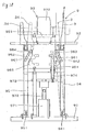
- a coil insertion apparatus 9 of this embodiment as shown in Fig. 18, has an upper plate portion 92 fixed via a supporting column (not shown) provided extended from a bottom plate portion 91, and a magazine 2 cradle 93 is provided on an upper portion thereof for holding the magazine.
- the magazine cradle 93 includes a flange portion 931, and a central protruding portion 932 having a cylindrical shape with a diameter smaller than the flange portion 931.
- the bottom plate portion 91 has a plurality of first arms 94 disposed swingably with a fulcrum 941 as a center, and a plurality of second arms 95 disposed swingably with a fulcrum 951 as a center.
- the first arm 94 has the insertion blade 3 on a top end thereof
- the second arm 95 has the preliminary formation blade 34 on a top end thereof.
- the first arm 94 has an elongated hole portion 942 capable of engaging a pin 963 provided in a hoisting plate 961.
- the second arm 95 has an elongated hole portion 952 capable of engaging a pin 964 provided in a second hoisting plate 962.
- the hoisting plate 961 is structured such that it is connected with a cylinder 971, a hoisting rod 972, a base plate 973, a connecting rod 974, and the like disposed on the bottom plate portion 91, and is lifted up and down with the rise and fall of the hoisting rod 972 driven by the cylinder 971.
- the elongated hole portions 942 and 952 provided in the first arm 94 and the second arm 95 have inclined elongated hole portions.
- engaging positions between the pins 963 and 964 and the elongated hole portions 942 and 952 shift from each other, whereby the first arm 94 and the second arm 95 are structured so as to swing with the fulcrums 941 and 951 as centers.
- the shapes of the elongated hole portion 942 in the first arm 94 and the elongated hole portion 952 in the second arm 95 are changed slightly, so that the swing amount or the like of the first arm 94 and the second arm 95 are different.
- each first arm 94 is provided with two parallel insertion blades 3, and the two insertion blades 3 are structured so as to move parallel together with the swing direction of the first arm 94.
- the swing direction of all first arms 94 is a direction along a radial direction A passing through the center of a tooth 15 located between two slots 10 in the stator 1.
- each second arm 95 is provided with two parallel preliminary formation blades 34, and the two preliminary formation blades 34 are structured so as to move parallel together with the swing direction of the second arm 95.
- the swing direction of all second arms 95 is a direction along a radial direction B passing through the center of the tooth 15 located between two slots 10 in the stator 1.
- a noteworthy point of this coil insertion apparatus 9, as shown in Fig. 18, is an angle of inclination ⁇ with respect to the vertical direction at a swing startup position of the insertion blade 3 is set to less than 5 degrees, and an angle of inclination with respect to the vertical direction at a swing end position is set to 0 degrees.
- all unipolar coils 8 can be simultaneously moved substantially linearly toward the stator core 1, with an angle formed between the coil inserting portion 801 in contact with the insertion blade 3 and the slot 10 in the stator 1 always maintained in a state less than 5 degrees.
- This embodiment is an example showing another example of the above-described insertion blade.
- an insertion blade 302 of this embodiment has a substantially L-shaped, and is composed of base portion 303 extending in the horizontal direction and a vertical blade portion 304 extending in the vertical direction. Also, a contact face 305 of the vertical base portion 304 is provided as a vertical plane. By moving the base portion 303 in the horizontal direction, the vertical blade 304 is structured so as to advance or retract while maintaining the vertical state of the contact portion 305.
- the angle formed between the coil inserting portion 801 and the slot 10 can be maintained at substantially 0 when in contact with the coil inserting portion 801, as well as when insertion into the slot 10 in the stator core 1 is completed.
- This embodiment is an example using a pair of upper and lower divided insertion blades 320 and 330 as the insertion blade, as shown in Figs. 21 and 22.
- the divided insertion blades 320 and 330 of this embodiment are a pair of upper and lower strips having tapered portions 325 and 335 on the sides of ends thereof, in which the ends are provided mutually opposing.
- Fig. 21 shows the motion of the divided insertion blades 320 and 330 and the unipolar coil 8 viewed from the radial direction of the stator core 1.
- Fig. 22 is an explanatory view showing the width dimensions of the portions in contact with the coil 8 of the divided insertion blades 320 and 330, which correspond to each operation of Fig. 21, as viewed from the axial direction of the stator core 1.
- the divided insertion blades 320 and 330 approach each other and overlap in the progression from (a) to (c).
- the width dimension of the contact portion with the unipolar coil 8 increases gradually along the tapered portions 325 and 335 so that the unipolar coil 8 is pressed gradually into the slot 10 in the stator core 1.
- An insertion pressure applied to the unipolar coil 8 is applied to four positions substantially symmetrical with respect to a winding center point of the unipolar coil 8 as shown in Fig. 29, which will be described later. Consequently, after reaching a state in which it is disposed substantially parallel to the slot 10, the unipolar coil 8 can be moved linearly while substantially maintaining that orientation.
- This embodiment is an example employing a magazine 202 having a different structure from the magazine of the first embodiment.
- the magazine 202 of this embodiment has a supporting rod portion 203 for forming a coil holding groove to hold the unipolar coil 8.
- a coil insertion step identical to the first embodiment can be carried out by a plurality of unipolar coils 8 held as shown in Figs. 23 and 24.
- This embodiment is an example employing a magazine 204 having a different structure from the magazine of the first embodiment as shown in Figs. 26 to 28.
- the magazine 204 of this embodiment has a pair of upper and lower magazine plates 205 extending from the outer radial direction to an inner peripheral surface for each pole.
- the unipolar coil 8 for a pole is held on a magazine plate 205 of the magazine 204, and mounted vertically in the axial direction of the stator core 1. Then, the unipolar coil 8 is moved into the slot 10 by pressing with an insertion blade or the like. Thereafter, the coil insertion step can be executed by the operation of pulling the magazine plate 205 holding each unipolar coil 8 one pole at a time, or a plurality of poles simultaneously in an outer radial direction.
- this embodiment shows examples of positions on the unipolar coil 8 to which an insertion pressure is applied in the coil insertion step.
- Fig. 29 is an example in which the insertion pressure is applied to a plurality of positions substantially symmetrical with respect to the winding center point of the unipolar coil 8, namely, pressure receiving regions F on four comers that are border portions between the coil inserting portion 801 and the coil end portion 802 of the unipolar coil 8.
- Fig. 30 is an example in which the insertion pressure is applied to a plurality of positions substantially symmetrical with respect to the winding center point of the unipolar coil 8, namely, the pressure receiving regions F on two comers of the four comers that are border portions between the coil inserting portion 801 and the coil end portion 802 of the unipolar coil 8.
- Figs. 31 and 34 are examples in which the insertion pressure is applied to the pressure receiving regions F on two coil end portions 802 of the unipolar coil 8.
- Figs. 32 and 33 are examples in which the insertion pressure is applied to the pressure receiving regions F on two coil inserting portions 801 of the unipolar coil 8.
- the unipolar coil 8 can be moved linearly while an angle formed between the coil inserting portion 801 of the unipolar coil 8 and the slot 10 is maintained at less than 5 degrees.
- the examples shown in Figs. 29 to 34 are mere examples, and the pressure receiving regions F, which are positions on which the insertion pressure is to be applied, can naturally be further changed.
- This embodiment is an example showing the divided insertion hook employed as the coil inserting mechanism instead of the insertion blade 3 of the first embodiment, as shown in Figs. 35 and 36.
- Fig. 35 shows one divided insertion hook 350 of a pair of divided insertion hooks separated on the front and rear surface sides of the magazine.
- This divided insertion hook 350 has a shape with an L-shaped cross section for hooking both end portions of the coil end portion 801, and is structured such that the insertion pressure is applied to the pressure receiving regions F on the four comers as described above in Fig. 29.
- Fig. 36 also shows one divided insertion hook 352 of a pair of divided insertion hooks separated on the front and rear surface sides of the magazine.
- This divided insertion hook 352 has a shape with a U-shaped cross section for hooking the entire coil end portions 801, and is structured such that the insertion pressure is applied as described above in Fig. 34.
- This embodiment is an example in which, as shown in Figs. 37 to 55, the coil formation step is carried out using a magazine (winding jig) 7 having a special structure that also functions as a winding jig for use in the coil formation step as the magazine.
- a winding jig (magazine) 7 and rotating device 74 are used as a coil forming device for forming motor coils composed of three unipolar coils 8 formed by winding wire 88 in a loop formation (see Fig. 50).
- the winding jig 7 has a base holder 70 and a plurality of spools 4 disposed on an outer peripheral surface of the base holder 70.
- Each spool 4 is disposed retractably with respect to the base holder 70, and structured such that any one spool 4 is capable of projecting from the other spools.
- the rotating device 74 is structured so as to rotate the entire winding jig 7 around an axis C in the advancing and retracting direction of the protruding spool 4.
- the base holder 70 has a disc shape.
- the base plate 70 includes a pair of upper and lower ring-shaped plates 71 and 72, and each ring-shaped plate has respective central through holes 710 and 720 and a plurality of positioning holes 712 and 722 in a periphery thereof.
- the central through holes 710 and 720 and the positioning holes 712 and 722 in a periphery thereof are used for determining an engagement position with the rotating device 74, which will be described later.
- the pair of upper and lower ring-shaped plates 71 and 72 are joined through separation plates 79 disposed along directions extending radially from the center thereof.
- four separation plates 79 are disposed at pitch with a 30-degree inner angle, and the four separation plates 79 are further disposed at a pitch with a 30-degree inner angle in opposing positions.
- respective spools 4 are disposed in a space with an approximately 30-degree inner angle provided between adjacent separation plates 79.
- three spools 4 are disposed adjacent to each other at opposing positions so that a total of six spools 4 are provided.
- the winding jig 7 of this embodiment is structured such that the separation plates 9 and the spools 4 can be further disposed at open positions on the outer peripheral surface of the disc-shaped base holder 70, so that a maximum of 12 spools 4 can be provided.
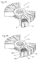
- each spool 4 is disposed retractably along the axis extending radially from the center point of the base holder 70. Further, each spool 4 has a fan-like shape expanding in width along the axis.
- each spool 4 is substantially fan-like in its entire shape as viewed from a front surface and rear surface thereof, and has a frame main body portion 42 providing a notch portion 420 in the center portion thereof. Further, step portions 425 are provided on both sides of the frame main body portion 42, such that when the unipolar coil 8 is formed, positioning thereof is carried out.
- forming blocks 43 and 44 are disposed detachably on the front and rear surface sides of the frame main body portion 42 in order to arrange the shape of the wound unipolar coil. These forming blocks 43 and 44 are also substantially fan-shaped and have notch portions 430 and 440 in the center portion thereof. The forming blocks 43 and 44 are fixed to the frame main body portion 42 by driving screws (not shown).
- the forming blocks 43 and 44 of this embodiment are formed thicker as the outer periphery becomes the inner periphery, such that the height of the formed unipolar coil increases as it approaches the inner periphery.
- the frame main body portion 42 has a rectangular through hole 429 in the axial direction from the notch portion 420 to the base holder 70.
- rod holes 428 which are circular through holes, are provided above and below the through hole 429.
- the spool 4 is disposed retractably on the base holder 70 by fixing a guide plate 41 via the through hole 429 onto the base holder 70.
- the guide plate 41 is composed of a base end portion 415 fixed to the base holder 70, and an end portion 410, the vertical dimension of which is increased in a substantial T-shape for restricting the advancing position of the spool 4. Then, the base end portion 415 of this guide plate 41 passes through the through hole 429 that opens to the bottom portion of the notch portion 420 of the frame main body portion 42, and rods 45 mounted with springs 46 pass through the rod holes 428 provided above and below the through hole 429 of the frame main body portion 42.
- the base end portion 415 of the guide plate 41 is held and fixed between the pair of upper and lower ring-shaped plates 71 and 72 of the base holder 70, and the ends of two rods 45 are fixed to the ring-shaped plates 71 and 72 ,while the other ends are fixed to the end portion 410 of the guide plate 41. Consequently, the spool 4 is fixed retractably with respect to the base holder 70.
- the spool 4 has positioning pins 48 above and below, which can advance and retract a pin end portion 481 by plucking and operating a pin head portion 480.
- the guide plate 41 has pin holes 418 and 419 capable of engaging the pin end portion 481.
- the spool 4 in a state where the pin end portion 481 of the positioning pin 48 is engaged with the pin hole 418, the spool 4 maintains a retracted state near the base holder 70.
- the positioning pin 48 is retracted so as to release the engaged state between the pin end portion 481 and the pin hole 418 ,and the spool 4 is advanced resisting the spring 46.
- the positioning pin 48 is then advanced again to engage the pin end portion 481 with the pin hole 419. Consequently, the spool 4 is structured such that it advances in the axial direction thereof, and is fixed at a position away from the base holder 70.
- the separation plates 79 provided extending from the outer peripheral surface of the base holder 70 exist on both sides of each spool 4 disposed as described above. Between the separation plate 79 and the spool 4, a predetermined gap is maintained that functions as the coil holding groove, which will be described later.
- the winding jig 7 of this embodiment a visible outline formed by the ends of the spools 4 when all spools 4 are retracted is circular around the center point of the base holder 70.
- the winding jig 7 of this embodiment is a shape capable of being disposed with each spool 4 opposing the inner peripheral surface of the stator core, which will be described later.
- the rotating device 74 of this embodiment includes a straight portion 741 provided extending from a drive shaft (not shown), and a bent portion 76 connected to the straight portion 741 via flanges 751 and 752, in which an end of the bent portion 76 has a connecting flange 77 for connecting with the winding jig 7.
- the bent portion 76 includes a first part 761 extending coaxially with the straight portion 741, a second part 762 provided extending and bent 90 degrees from the first part, a third part 763 bent a further 90 degrees from the second part 762 and parallel to the straight portion 741, and a fourth part 764 bent a further 90 degrees from the third part 763.
- the connecting flange 77 is disposed at an end of the fourth part 764.
- the connecting flange 77 is adjusted in position such that when it is connected to the base holder 70 of the winding jig 7, the center points in the direction of thickness and the radial direction of the base holder 70 are located on the axis of the straight portion 741.
- the fixing position of the winding jig 7 in its circumferential direction and the connecting flange 77 are structured appropriately adjustable at a position in which the axis C of the spool 4 coincides with a rotation center C2 of the straight portion 741 of the rotating device 74.
- a spool projection step for advancing the first spool 4a such that it protrudes from other spools 4 is carried out as shown in Fig. 41.
- the positioning pin 48 (Figs. 51 to 53) fixing the spool 4a at its retracted position is released so as to allow the spool 4a to advance resisting the spring 46, and it is then fixed again at its advanced position with the positioning pin 48.
- the wire 88 is supplied in a single direction from above, and an end thereof is fixed to the winding jig 7.
- a fixing method it may be fixed at a specific position with a special fixing device, or it may be tied up at an arbitrary position of the spool 7. In this embodiment, the latter method was adopted.
- the winding step is executed by supplying the wire 88 to the projected spool 4a from a single direction, and driving the rotation device 74 to rotate the entire winding jig 7 around the axis C of the spool 4a. Consequently, as shown in Fig. 43, the wire 88 wound around the projected spool 4a completes the formation of the first unipolar coil 8.
- a spool retraction step for retracting the first spool 4a on which the unipolar coil 8 is formed is executed.
- the spool 4a is fixed at its retracted position by again operating the positioning pin 48 (Figs. 51 to 53).
- the coil end portions 802 located above and below the loop thereof are exposed on the front and rear of the spool 4, while the coil inserting portions 801 located on the right and left are accommodated between the separation plate 79 and the spool 4.
- a second spool 4b adjacent to the first spool 4a that formed the unipolar coil 8 is advanced along the axis C, so that it is projected outward from the other spool.4, and fixed at an advanced position as described above.
- the engagement position between the winding jig 7 and the rotating device 74 is changed so that the rotation center of the rotating device 74 is made to coincide with the axis center of the second spool 4b.
- a crossover wire 885 continuous from the unipolar coil 8 held by the first spool 4a passes below the second spool 4b, and the wire 88 continuous from this is supplied from a single direction above identical to the previous description.
- the winding step of supplying the wire 88 to the projected spool 4b from a single direction, and rotating the entire winding jig 7 around the axis C of the spool 4b is executed.
- the rotation direction at this time is the reverse of the direction in the case of the first spool 4a. Consequently, as shown in Fig. 47, the wire 88 is wound around the projected spool 4b, so that formation of a second unipolar coil 8, the winding direction of which is opposite to the first unipolar coil 8, is completed.
- the second spool 4b that formed the unipolar coil 8 is retracted and fixed at its retracted position as described above.
- the coil end portions 802 located above and below the loop thereof are exposed on the front and rear of the spool 4, and the coil inserting portions 801 located on the right and left are accommodated in a gap between the separation plate 79 and the spool 4.
- a third spool 4c adjacent to the second spool 4b is advanced along the axis C so that it is projected outward from the other spools 4, and fixed at an advanced position. Further, in this case as well, by changing the engagement position between the winding jig 7 and the rotating device 74 before or after the spool projection step, the rotation center C2 (Figs. 37 and 38) of the rotating device 74 is made to coincide with the axis C of the third spool 4c.
- the wire 88 continuous from the crossover wire 885 extending from the unipolar coil 8 held by the second spool 4b is supplied from a single direction above identical to the above description.
- the winding step is carried out by supplying the wire 88 to the projected spool 4c from a single direction as shown in Figs. 48 and 49, and rotating the entire winding jig 7 around the axis C of the spool 4c.
- the rotation direction at this time is the reverse of the direction in the case of the second spool 4c. Consequently, as shown in Fig. 49, the wire 88 is wound around the projected spool 4c, so that formation of a third unipolar coil 8, the winding direction of which is opposite to the second unipolar coil 8, is completed.
- the third spool 4c that formed the unipolar coil 8 is retracted as shown in Fig. 50, and is retracted and fixed at its retracted position as described above.
- the coil inserting portion 801 of the third unipolar coil 8 formed around the spool 4c is accommodated in a gap between the separation plate 79 and the spool 4.
- the coil is completed by combining the three unipolar coils 8 together such that their winding directions are alternately reversed.
- another coil can be completed by combining three unipolar coils 8 together with their winding directions alternately reversed according to the same procedure as described above.
- the winding jig 7 having the above-described structure including the base holder 70 and the spool 4, and the rotating device 74 are employed. Further, as described above, the spool projection step, the winding step, and the spool retraction step are carried out in succession for each spool.
- the winding step is carried out by rotating the entire winding jig around the axis C of the projected spool 4.
- the wire 88 can be supplied from a single direction, and the unipolar coil 8 can be formed on the spool 4 without twisting the wire 88.
- the winding step is carried out after the spool projection step and the spool retraction step is carried out after the winding step. Namely, when changing the spool 4 undergoing the winding step, it can be changed by advancing or retracting the spool 4 in the spool projection step or the spool retraction step, thereby eliminating the need to specially provide a space between adjacent spools 4 for supplying wire. Moreover, the length of the crossover wire 885 obtained between the unipolar coils 8 can be kept sufficiently short.
- each spool 4 of the winding jig 7 has a substantially fan-like shape as described above, and the forming blocks 43 and 44 are disposed on the front and rear surface sides thereof.
- the forming blocks 43 and 44, as described above, have increasing thickness in the direction from outward to inward.
- the shape of a plurality of wire loops constituting this unipolar coil changes along the axis C of the spool 4.
- the width of the wire loops constituting the unipolar coil 8 increases along the fan-shaped spool 4 as it proceeds outward, and the height thereof decreases along the shape of the forming blocks 43 and 44. Therefore, as described above, the arrangement of the coil end portion 802 when the coil is mounted on the stator core can be optimized.
- a visible outline formed by the ends of the spools 4 is circular, and each spool 4 can be positioned opposing the inner peripheral surface of the stator core, which will be described later.
- the separation plates 79 provided extending from the outer peripheral surface of the base holder 70 exist on both sides of each spool 4.
- a gap between the separation plate 79 and the spool 4 functions as the coil holding groove.
- the coil (see Fig. 50) is inserted into and disposed on the slots 10 provided in the inner peripheral surface of the ring-shaped stator core 1.
- representation of the coil (unipolar coil 8) is omitted in order to clarify the motion of the insertion blades 3 and the like, which will be described later.
- the motor constituted with the stator core 1 is a 3-phase DC brushless motor.
- the stator core 1 of this embodiment is also produced by laminating ring-shaped electromagnetic steel plates, and as shown in Figs. 54 and 55, includes the slots 10 into which the coil is inserted on an inner peripheral surface thereof.
- the stator core 1 is provided with 72 slots 10 for disposing a total of 36 unipolar coils 8. Every 12 unipolar coils 8 is of a single phase. As described above, in this embodiment, coils constituted of a combination of three unipolar coils 8 are produced in pair by the winding jig 7, and these are simultaneously mounted on the stator core 1. Executing this operation six times mounts all necessary unipolar coils 8 onto the stator core 1.
- the winding jig 7 is disposed in an inner portion of the stator core 1 such that a coil holding groove 790 formed between the spool 4 and the separation plate 79 on the winding jig 7 opposes the slot 10 in the stator core 1.
- the insertion blade 3 is inserted into the coil holding groove 790 of the winding jig 7.
- the notch portion 420 provided in the frame main body portion 42 of the spool 4 of the winding jig 7, and the notch portions 430 and 440 (see Fig. 39) provided in the upper and lower forming blocks 43 and 44 serve as a preliminary forming groove 795 into which the preliminary formation blade 34 is inserted.
- the insertion blade 3 is advanced in a direction from the center to the outer periphery of the coil holding groove 790, while the preliminary formation blade 34 is advanced in a direction from the center to the outer periphery of the preliminary forming groove 795. Consequently, the unipolar coil 8 is pushed by the insertion blade 3, so that it is moved substantially linearly from the coil holding groove 790 into the slot 10 in the stator core 1. Further, the above and below coil end portions 802 (Fig. 50) protruding from the stator core 1 of the unipolar coil 8 are subjected to preliminary formation in which they are pressed by the preliminary formation blades 34 to be deformed outward.
- Such advancing actions of the insertion blade 3 and the preliminary formation blade 34 are simultaneously carried out for six unipolar coils 8, so that the six unipolar coils 8 are inserted into the slots 10 in the stator core 1 at the same time.
- the second preliminary formation is carried out with the pair of upper and lower formers 66 (see Fig. 12) identical to the first embodiment.
- the former 66 has a ring shape, and a forming face 660 for arranging the coil into a desired shape provided on a side opposing the stator core 1.
- each former 66 is provided with a notch portion 665 for preventing interference between the insertion blade 3 and the preliminary formation blade 34. The former can be pressed against the stator core 1, while maintaining the insertion blade 3 and the preliminary formation blade 34 in an advanced state.
- the pair of upper and lower formers 66 having such a structure are respectively advanced to the stator core 1 from above and below, and pressed against the stator core 1. Consequently, as described above, the second preliminary formation is carried out such that the coil end portions 802 protruding from above and below the stator core 1 of the six unipolar coils 8 disposed on the stator core 1 falls toward the stator core 1.
- a pair of coils constituted of a combination of three new unipolar coils 8 are formed on the winding jig 7 with the above-described coil forming apparatus.
- moving of the coil directly to the stator core 1 from the winding jig 7, in addition to the preliminary formation and the second preliminary formation are carried out.
- a total of 36 unipolar coils 8 are mounted on the stator core 1.
- the formation by the formers, which is carried out as a final second preliminary formation, is executed on all 36 unipolar coils, which is a main formation step for arranging the entire coil.
- the formation of the six unipolar coils to the second preliminary formation is carried out as a sequential operation, and this operation is repeated six times; however, a plurality of winding jigs 7 may be employed to raise efficiency. Further, the process can be streamlined by increasing the quantity of the spools 4 from 6 to 12, and moving the 12 unipolar coils 8 to the stator core 1 all at once.
- the unipolar coil 8 can be linearly inserted into the slot 10 without changing the orientation of the unipolar coil 8. Therefore, the length of the coil in the vertical direction does not have to be made longer than required.
- the coil can be directly moved from the spool 4 to the stator core 1 after forming the coil. Then, after forming the coil, the coil can be mounted on the stator core extremely effectively without necessitating transfer of the coil to another coil transfer device from the spool. As already explained above, this is due to the excellent structure of the winding jig 7 described above.
- the coil can be directly inserted from the winding jig 7 into the stator core 1, the coil can be moved easily even if the length of the crossover wire for connecting the unipolar coils 8 to each other is short.
Landscapes
- Engineering & Computer Science (AREA)
- Manufacturing & Machinery (AREA)
- Power Engineering (AREA)
- Manufacture Of Motors, Generators (AREA)
Applications Claiming Priority (3)
| Application Number | Priority Date | Filing Date | Title |
|---|---|---|---|
| JP2001232571 | 2001-07-31 | ||
| JP2001232571 | 2001-07-31 | ||
| PCT/JP2002/007749 WO2003012961A1 (fr) | 2001-07-31 | 2002-07-30 | Procede de fabrication d'un moteur et appareil d'insertion d'un enroulement |
Publications (1)
| Publication Number | Publication Date |
|---|---|
| EP1414137A1 true EP1414137A1 (fr) | 2004-04-28 |
Family
ID=19064474
Family Applications (3)
| Application Number | Title | Priority Date | Filing Date |
|---|---|---|---|
| EP02755693A Withdrawn EP1414139A1 (fr) | 2001-07-31 | 2002-07-30 | Procede de fabrication d'un moteur |
| EP02751810A Expired - Fee Related EP1414138B1 (fr) | 2001-07-31 | 2002-07-30 | Procédé de production de moteurs |
| EP02751809A Withdrawn EP1414137A1 (fr) | 2001-07-31 | 2002-07-30 | Procede de fabrication d'un moteur et appareil d'insertion d'un enroulement |
Family Applications Before (2)
| Application Number | Title | Priority Date | Filing Date |
|---|---|---|---|
| EP02755693A Withdrawn EP1414139A1 (fr) | 2001-07-31 | 2002-07-30 | Procede de fabrication d'un moteur |
| EP02751810A Expired - Fee Related EP1414138B1 (fr) | 2001-07-31 | 2002-07-30 | Procédé de production de moteurs |
Country Status (6)
| Country | Link |
|---|---|
| US (3) | US20040055139A1 (fr) |
| EP (3) | EP1414139A1 (fr) |
| JP (3) | JP4259322B2 (fr) |
| KR (2) | KR100895781B1 (fr) |
| CN (2) | CN1465127A (fr) |
| WO (3) | WO2003012961A1 (fr) |
Cited By (2)
| Publication number | Priority date | Publication date | Assignee | Title |
|---|---|---|---|---|
| EP1526630A1 (fr) * | 2002-07-30 | 2005-04-27 | Aisin Aw Co., Ltd. | Procede de fabrication de moteur |
| US7275299B2 (en) | 2002-07-30 | 2007-10-02 | Aisin Aw Co., Ltd. | Motor manufacturing process |
Families Citing this family (37)
| Publication number | Priority date | Publication date | Assignee | Title |
|---|---|---|---|---|
| JP3752431B2 (ja) * | 2001-02-28 | 2006-03-08 | 株式会社日立製作所 | 回転電機及びその製造方法 |
| DE102004010446A1 (de) * | 2004-03-01 | 2005-09-22 | Elektra Gmbh | Polspulen für die Statorwicklung eines geschalteten Reluktanzmotors |
| JP3913242B2 (ja) * | 2004-09-13 | 2007-05-09 | 日特エンジニアリング株式会社 | 多極電機子の巻線方法及び巻線装置 |
| FR2896352B1 (fr) * | 2006-01-16 | 2014-08-22 | Valeo Equip Electr Moteur | Dispositif de transfert radial d'un bobinage de stator |
| JP4234749B2 (ja) * | 2006-10-19 | 2009-03-04 | 株式会社日立製作所 | 回転電機、クランク形状の連続巻きコイル、分布巻き固定子及びそれらの形成方法 |
| JP4940252B2 (ja) * | 2009-02-03 | 2012-05-30 | 株式会社日立製作所 | 回転電機の製造方法 |
| JP5530121B2 (ja) * | 2009-05-15 | 2014-06-25 | 日特エンジニアリング株式会社 | ステータコイル及びその製造方法及び巻き線機 |
| EP2449658A4 (fr) * | 2009-06-29 | 2016-03-02 | Tm4 Inc | Systèmes et procédés d'insertion d'isolateurs et de bobines dans les encoches du stator d'une machine électrique |
| KR101084349B1 (ko) * | 2009-10-21 | 2011-11-17 | 주식회사 자온지 | 히트파이프형 방열장치의 제조방법 |
| WO2011132228A1 (fr) | 2010-04-22 | 2011-10-27 | 日立オートモティブシステムズ株式会社 | Stator et son procédé de fabrication |
| JP5059165B2 (ja) * | 2010-05-14 | 2012-10-24 | 日立オートモティブシステムズ株式会社 | 回転電機 |
| CN103430259B (zh) * | 2011-03-18 | 2016-05-11 | Sht有限公司 | 自动卷线机、空芯线圈及其卷线方法 |
| JP2012257410A (ja) * | 2011-06-09 | 2012-12-27 | Toyota Motor Corp | モータ固定子の製造方法、モータ固定子の製造装置 |
| JP5648611B2 (ja) | 2011-09-06 | 2015-01-07 | 株式会社豊田自動織機 | 回転電機のステータの製造装置 |
| US9118225B2 (en) | 2012-08-24 | 2015-08-25 | Caterpillar Inc. | Coil with twisted wires and stator assembly of a rotary electric machine |
| JP5936270B2 (ja) | 2012-09-20 | 2016-06-22 | 日特エンジニアリング株式会社 | 巻線装置及び巻線方法 |
| DE102013212892A1 (de) * | 2013-07-02 | 2015-01-08 | Robert Bosch Gmbh | Stator für eine elektrische Maschine |
| JP6344761B2 (ja) * | 2014-05-20 | 2018-06-20 | 日特エンジニアリング株式会社 | ステータの製造装置 |
| CN105305743B (zh) * | 2014-07-30 | 2017-09-29 | 东元电机股份有限公司 | 定子绕线工具及其绕线方法 |
| JP6315808B2 (ja) * | 2014-08-08 | 2018-04-25 | 日特エンジニアリング株式会社 | コイル製造装置 |
| EP3145058B8 (fr) * | 2014-09-01 | 2018-12-19 | Aisin Aw Co., Ltd. | Procédé d'assemblage d'un stator et stator |
| DE102016111478B4 (de) | 2015-12-15 | 2022-05-19 | Grob-Werke Gmbh & Co. Kg | Verfahren für den Einbau eines Drahtpaketes in eine elektrische Maschine |
| CN105720761B (zh) * | 2016-04-09 | 2018-05-01 | 哈尔滨工业大学 | 一种紧凑型永磁无刷电机分块式铁心绕线方法 |
| CA3035592A1 (fr) * | 2016-09-02 | 2018-03-08 | Ats Automation Tooling Systems Inc. | Procede et systeme d'assemblage de conducteurs en epingle a cheveux avec un noyau de stator |
| JP2018098925A (ja) * | 2016-12-14 | 2018-06-21 | トヨタ自動車株式会社 | 固定子製造装置 |
| US11196312B2 (en) * | 2017-02-21 | 2021-12-07 | Panasonic Intellectual Property Management Co., Ltd. | Motor |
| CN108521205B (zh) * | 2018-04-23 | 2019-08-02 | 昆山富通电子有限公司 | 一种铁芯绕线设备 |
| CN108494193B (zh) * | 2018-04-23 | 2019-08-02 | 昆山富通电子有限公司 | 一种铁芯绕线设备的旋转装置 |
| CN108494194B (zh) * | 2018-04-23 | 2019-08-02 | 昆山富通电子有限公司 | 一种用于铁芯绕线的旋转装置 |
| DE102018220216A1 (de) | 2018-07-30 | 2020-01-30 | Sms Group Gmbh | Rolle für einen Rollenherdofen |
| JPWO2020195156A1 (fr) * | 2019-03-27 | 2020-10-01 | ||
| JP7373891B2 (ja) * | 2019-05-09 | 2023-11-06 | Nittoku株式会社 | コイル挿入装置及びコイル挿入方法 |
| CN110266161B (zh) * | 2019-07-04 | 2020-12-11 | 超仪科技股份有限公司 | 漆包线的数控绕线工艺 |
| US11411477B2 (en) * | 2020-06-22 | 2022-08-09 | Yoshio Kato | Coil insertion method and coil insertion device |
| CN111786520B (zh) * | 2020-07-10 | 2023-03-24 | 陕西航空电气有限责任公司 | 一种发电机定子集中绕组嵌线工装及其嵌线方法 |
| CN112967873B (zh) * | 2021-02-02 | 2022-03-08 | 中国科学院电工研究所 | 组合式变压器线圈支撑系统 |
| DE102022101153A1 (de) * | 2022-01-19 | 2023-07-20 | Schaeffler Technologies AG & Co. KG | Verfahren für das Wickeln von windungsspezifischen Drahtlängen und Rotor oder Stator mit einer Spulenwicklung mit windungsspezifischen Drahtlängen |
Family Cites Families (13)
| Publication number | Priority date | Publication date | Assignee | Title |
|---|---|---|---|---|
| US3324536A (en) * | 1965-05-03 | 1967-06-13 | Donald E Hill | Coil assembling apparatus |
| US3685118A (en) * | 1970-04-13 | 1972-08-22 | Industra Products | Wire coil stripper and inserting device |
| JPS51138803A (en) * | 1975-05-28 | 1976-11-30 | Hitachi Ltd | Inserting device of coil into electric motor |
| JPS5594567A (en) * | 1979-01-10 | 1980-07-18 | Nippon Denso Co Ltd | Winding method for winding unit of rotary machine |
| JPS5619363A (en) * | 1979-07-19 | 1981-02-24 | Matsushita Electric Ind Co Ltd | Inserting method for coil winding and inserting device for coil winding |
| JPS5846850A (ja) | 1981-09-11 | 1983-03-18 | Toshiba Corp | コイル巻枠 |
| JPS631349A (ja) * | 1986-06-20 | 1988-01-06 | Yaskawa Electric Mfg Co Ltd | 巻線装置 |
| JPH07118887B2 (ja) * | 1986-09-08 | 1995-12-18 | 株式会社三ツ葉電機製作所 | 回転電機のステータコイル巻装装置 |
| US4908541A (en) * | 1986-08-28 | 1990-03-13 | Mitsuba Electric Mfg., Co., Ltd. | Air-cooled layered coil vehicle AC generator stator |
| US4750258A (en) * | 1986-10-14 | 1988-06-14 | Emerson Electric Co. | Apparatus for and method of simultaneously, axially inserting multiple pole, multiple phase windings |
| JPH099588A (ja) * | 1995-06-21 | 1997-01-10 | Toyota Motor Corp | モータのステータ作製方法 |
| US6389678B1 (en) * | 1996-05-31 | 2002-05-21 | Emerson Electric Co. | Method of constructing a salient pole motor |
| JP3791426B2 (ja) * | 2001-02-20 | 2006-06-28 | 日産自動車株式会社 | コイル挿入方法および装置 |
-
2002
- 2002-07-30 EP EP02755693A patent/EP1414139A1/fr not_active Withdrawn
- 2002-07-30 US US10/433,092 patent/US20040055139A1/en not_active Abandoned
- 2002-07-30 EP EP02751810A patent/EP1414138B1/fr not_active Expired - Fee Related
- 2002-07-30 WO PCT/JP2002/007749 patent/WO2003012961A1/fr not_active Application Discontinuation
- 2002-07-30 JP JP2003518018A patent/JP4259322B2/ja not_active Expired - Fee Related
- 2002-07-30 US US10/433,048 patent/US7185413B2/en not_active Expired - Fee Related
- 2002-07-30 CN CN02802559A patent/CN1465127A/zh active Pending
- 2002-07-30 KR KR1020037004617A patent/KR100895781B1/ko not_active IP Right Cessation
- 2002-07-30 WO PCT/JP2002/007750 patent/WO2003012962A1/fr not_active Application Discontinuation
- 2002-07-30 EP EP02751809A patent/EP1414137A1/fr not_active Withdrawn
- 2002-07-30 JP JP2003518019A patent/JP4259323B2/ja not_active Expired - Fee Related
- 2002-07-30 WO PCT/JP2002/007751 patent/WO2003012963A1/fr active Application Filing
- 2002-07-30 JP JP2003518017A patent/JP4403801B2/ja not_active Expired - Fee Related
- 2002-07-30 US US10/433,097 patent/US20040098856A1/en not_active Abandoned
- 2002-07-30 CN CN028025601A patent/CN1465128B/zh not_active Expired - Fee Related
- 2002-07-30 KR KR10-2003-7004618A patent/KR20040018299A/ko not_active Application Discontinuation
Non-Patent Citations (1)
| Title |
|---|
| See references of WO03012961A1 * |
Cited By (3)
| Publication number | Priority date | Publication date | Assignee | Title |
|---|---|---|---|---|
| EP1526630A1 (fr) * | 2002-07-30 | 2005-04-27 | Aisin Aw Co., Ltd. | Procede de fabrication de moteur |
| EP1526630A4 (fr) * | 2002-07-30 | 2006-10-25 | Aisin Aw Co | Procede de fabrication de moteur |
| US7275299B2 (en) | 2002-07-30 | 2007-10-02 | Aisin Aw Co., Ltd. | Motor manufacturing process |
Also Published As
| Publication number | Publication date |
|---|---|
| EP1414138A4 (fr) | 2009-04-29 |
| EP1414138B1 (fr) | 2012-10-24 |
| JPWO2003012963A1 (ja) | 2004-11-25 |
| JPWO2003012962A1 (ja) | 2004-11-25 |
| WO2003012962A1 (fr) | 2003-02-13 |
| KR20040018299A (ko) | 2004-03-03 |
| JP4259322B2 (ja) | 2009-04-30 |
| WO2003012961A1 (fr) | 2003-02-13 |
| CN1465127A (zh) | 2003-12-31 |
| KR100895781B1 (ko) | 2009-05-07 |
| JP4403801B2 (ja) | 2010-01-27 |
| US20040068858A1 (en) | 2004-04-15 |
| EP1414139A1 (fr) | 2004-04-28 |
| KR20040028639A (ko) | 2004-04-03 |
| JP4259323B2 (ja) | 2009-04-30 |
| CN1465128A (zh) | 2003-12-31 |
| US20040055139A1 (en) | 2004-03-25 |
| US7185413B2 (en) | 2007-03-06 |
| JPWO2003012961A1 (ja) | 2004-11-25 |
| EP1414138A1 (fr) | 2004-04-28 |
| US20040098856A1 (en) | 2004-05-27 |
| WO2003012963A1 (fr) | 2003-02-13 |
| CN1465128B (zh) | 2010-04-21 |
Similar Documents
| Publication | Publication Date | Title |
|---|---|---|
| EP1414137A1 (fr) | Procede de fabrication d'un moteur et appareil d'insertion d'un enroulement | |
| JP4492347B2 (ja) | コイル形成装置及びコイル形成方法 | |
| KR100965500B1 (ko) | 모터의 제조방법 | |
| KR100965696B1 (ko) | 권선 방법 및 권선 장치 | |
| US7275299B2 (en) | Motor manufacturing process | |
| US20180040421A1 (en) | Winding method | |
| JP2007006677A (ja) | ステータコアの巻線方法および巻線装置 | |
| US7467648B2 (en) | Coil forming and inserting device and coil forming and inserting method | |
| JP2003164122A (ja) | 固定子の製造方法及び製造装置 | |
| JP4192727B2 (ja) | コイル巻線機 | |
| JP4259066B2 (ja) | モータの製造方法 | |
| JP2005318694A (ja) | ステータ鉄心の巻線装置、及びステータの製造方法 | |
| KR20230025025A (ko) | 권선 장치 및 권선 방법 | |
| JP2003158844A (ja) | コイル形成装置及びコイル形成方法 |
Legal Events
| Date | Code | Title | Description |
|---|---|---|---|
| PUAI | Public reference made under article 153(3) epc to a published international application that has entered the european phase |
Free format text: ORIGINAL CODE: 0009012 |
|
| 17P | Request for examination filed |
Effective date: 20030813 |
|
| AK | Designated contracting states |
Kind code of ref document: A1 Designated state(s): AT BE BG CH CY CZ DE DK EE ES FI FR GB GR IE IT LI LU MC NL PT SE SK TR |
|
| STAA | Information on the status of an ep patent application or granted ep patent |
Free format text: STATUS: THE APPLICATION IS DEEMED TO BE WITHDRAWN |
|
| 18D | Application deemed to be withdrawn |
Effective date: 20070201 |