EP1413039B1 - Switched-mode power supply with a damping network - Google Patents
Switched-mode power supply with a damping network Download PDFInfo
- Publication number
- EP1413039B1 EP1413039B1 EP02754893A EP02754893A EP1413039B1 EP 1413039 B1 EP1413039 B1 EP 1413039B1 EP 02754893 A EP02754893 A EP 02754893A EP 02754893 A EP02754893 A EP 02754893A EP 1413039 B1 EP1413039 B1 EP 1413039B1
- Authority
- EP
- European Patent Office
- Prior art keywords
- diode
- switched
- power supply
- mode power
- secondary winding
- Prior art date
- Legal status (The legal status is an assumption and is not a legal conclusion. Google has not performed a legal analysis and makes no representation as to the accuracy of the status listed.)
- Expired - Lifetime
Links
- 238000013016 damping Methods 0.000 title description 27
- 239000003990 capacitor Substances 0.000 claims description 51
- 238000004804 winding Methods 0.000 claims description 49
- 238000000034 method Methods 0.000 description 6
- 230000010355 oscillation Effects 0.000 description 4
- 238000004146 energy storage Methods 0.000 description 3
- 230000033228 biological regulation Effects 0.000 description 1
- 238000006243 chemical reaction Methods 0.000 description 1
- 230000008878 coupling Effects 0.000 description 1
- 238000010168 coupling process Methods 0.000 description 1
- 238000005859 coupling reaction Methods 0.000 description 1
- 230000001419 dependent effect Effects 0.000 description 1
- 238000011161 development Methods 0.000 description 1
- 230000018109 developmental process Effects 0.000 description 1
- 230000000694 effects Effects 0.000 description 1
- 238000011084 recovery Methods 0.000 description 1
- 230000006641 stabilisation Effects 0.000 description 1
- 238000011105 stabilization Methods 0.000 description 1
- 238000011144 upstream manufacturing Methods 0.000 description 1
Images

Classifications
-
- H—ELECTRICITY
- H02—GENERATION; CONVERSION OR DISTRIBUTION OF ELECTRIC POWER
- H02M—APPARATUS FOR CONVERSION BETWEEN AC AND AC, BETWEEN AC AND DC, OR BETWEEN DC AND DC, AND FOR USE WITH MAINS OR SIMILAR POWER SUPPLY SYSTEMS; CONVERSION OF DC OR AC INPUT POWER INTO SURGE OUTPUT POWER; CONTROL OR REGULATION THEREOF
- H02M3/00—Conversion of DC power input into DC power output
- H02M3/22—Conversion of DC power input into DC power output with intermediate conversion into AC
- H02M3/24—Conversion of DC power input into DC power output with intermediate conversion into AC by static converters
- H02M3/28—Conversion of DC power input into DC power output with intermediate conversion into AC by static converters using discharge tubes with control electrode or semiconductor devices with control electrode to produce the intermediate AC
-
- H—ELECTRICITY
- H02—GENERATION; CONVERSION OR DISTRIBUTION OF ELECTRIC POWER
- H02M—APPARATUS FOR CONVERSION BETWEEN AC AND AC, BETWEEN AC AND DC, OR BETWEEN DC AND DC, AND FOR USE WITH MAINS OR SIMILAR POWER SUPPLY SYSTEMS; CONVERSION OF DC OR AC INPUT POWER INTO SURGE OUTPUT POWER; CONTROL OR REGULATION THEREOF
- H02M1/00—Details of apparatus for conversion
- H02M1/32—Means for protecting converters other than automatic disconnection
- H02M1/34—Snubber circuits
-
- H—ELECTRICITY
- H02—GENERATION; CONVERSION OR DISTRIBUTION OF ELECTRIC POWER
- H02M—APPARATUS FOR CONVERSION BETWEEN AC AND AC, BETWEEN AC AND DC, OR BETWEEN DC AND DC, AND FOR USE WITH MAINS OR SIMILAR POWER SUPPLY SYSTEMS; CONVERSION OF DC OR AC INPUT POWER INTO SURGE OUTPUT POWER; CONTROL OR REGULATION THEREOF
- H02M3/00—Conversion of DC power input into DC power output
- H02M3/22—Conversion of DC power input into DC power output with intermediate conversion into AC
- H02M3/24—Conversion of DC power input into DC power output with intermediate conversion into AC by static converters
- H02M3/28—Conversion of DC power input into DC power output with intermediate conversion into AC by static converters using discharge tubes with control electrode or semiconductor devices with control electrode to produce the intermediate AC
- H02M3/325—Conversion of DC power input into DC power output with intermediate conversion into AC by static converters using discharge tubes with control electrode or semiconductor devices with control electrode to produce the intermediate AC using devices of a triode or a transistor type requiring continuous application of a control signal
- H02M3/335—Conversion of DC power input into DC power output with intermediate conversion into AC by static converters using discharge tubes with control electrode or semiconductor devices with control electrode to produce the intermediate AC using devices of a triode or a transistor type requiring continuous application of a control signal using semiconductor devices only
-
- H—ELECTRICITY
- H02—GENERATION; CONVERSION OR DISTRIBUTION OF ELECTRIC POWER
- H02M—APPARATUS FOR CONVERSION BETWEEN AC AND AC, BETWEEN AC AND DC, OR BETWEEN DC AND DC, AND FOR USE WITH MAINS OR SIMILAR POWER SUPPLY SYSTEMS; CONVERSION OF DC OR AC INPUT POWER INTO SURGE OUTPUT POWER; CONTROL OR REGULATION THEREOF
- H02M1/00—Details of apparatus for conversion
- H02M1/32—Means for protecting converters other than automatic disconnection
- H02M1/34—Snubber circuits
- H02M1/346—Passive non-dissipative snubbers
-
- Y—GENERAL TAGGING OF NEW TECHNOLOGICAL DEVELOPMENTS; GENERAL TAGGING OF CROSS-SECTIONAL TECHNOLOGIES SPANNING OVER SEVERAL SECTIONS OF THE IPC; TECHNICAL SUBJECTS COVERED BY FORMER USPC CROSS-REFERENCE ART COLLECTIONS [XRACs] AND DIGESTS
- Y02—TECHNOLOGIES OR APPLICATIONS FOR MITIGATION OR ADAPTATION AGAINST CLIMATE CHANGE
- Y02B—CLIMATE CHANGE MITIGATION TECHNOLOGIES RELATED TO BUILDINGS, e.g. HOUSING, HOUSE APPLIANCES OR RELATED END-USER APPLICATIONS
- Y02B70/00—Technologies for an efficient end-user side electric power management and consumption
- Y02B70/10—Technologies improving the efficiency by using switched-mode power supplies [SMPS], i.e. efficient power electronics conversion e.g. power factor correction or reduction of losses in power supplies or efficient standby modes
Definitions
- the invention is based on a switched-mode power supply having a transformer and having a switching transistor, which is connected in series with the primary winding of the transformer.
- Switched-mode power supplies of this type are used, for example, in televisions, video recorders or computer monitors, and preferably operate as flyback converters, in a power range from about 50 to 150 watts.
- This network normally has a capcitor in parallel with the primary winding, which capcitor is charged when the switching transistor is switched off, and whose energy is then emitted to an energy-storage capacitor on the input side, or is consumed in a resistor and converted into heat.
- a damping network of this type is known, by way of example, from DE-A-40 29 221.
- EP-A-0 695 023 discloses a switched-mode power supply which, in addition to a damping network in parallel with the primary winding, also has a second damping network in parallel with a winding on the secondary side of the transformer.
- a series circuit formed by a capcaitor and a second diode is connected in parallel with a rectifying diode, which produces a desired output voltage across a charge-storage capacitor, and the centre point of this series circuit is connected to a reference potential via a diode and an inductance. Energy is in this case likewise transferred to the charge-storage capacitor via this capacitor, for energy recovery purposes, when the switching transistor switches off.
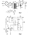
- This switched-mode power supply has a network connection UN, to which a network rectifier 1 followed by an energy-storage capacitor C0 are connected, across which a DC voltage U0 is produced. This is applied to a primary winding WP of a transformer TR, in series with which a switching transistor T1 is connected.
- the switching transistor T1 is driven in a known manner by a driver circuit 2, illustrated only symbolically here, with switching pulses 3.
- the switched-mode power supply in this case operates in particular in the flyback converter mode, in which energy is transferred from the transformer TR to one or more secondary windings during the phase in which the switching transitor T1 is switched off.
- a damping network for damping voltage spikes when the transistor T1 is switched off is connected in parallel with the primary winding WP.
- This damping network has a series circuit formed by a capacitor Cs and a diode Ds, with a resistor Rs being connected in parallel with its diode.
- the voltage spikes which are produced when the switching transistor T1 switches off are in this case absorbed by the capacitor Cs and are partially fed back via the diode Ds to the energy-storage capacitor C0, while the remainder is converted into heat in the resistor Rs.
- the switched-mode power supply has a secondary winding W1, which provides a desired output voltage U1 across a rectifier diode D1 and a charge-storage capacitor C1.
- a damping network is likewise coupled to the secondary winding W1.
- This damping network has a first series circuit with a capacitor C2 and a diode D2 in parallel with the diode D1, as well as a second series circuit with an inductance L1 and a diode D4, which is arranged between a tap a on the first series circuit and a reference potential.
- a resistor R1 is also connected in parallel with the inductance L1 and is used to damp oscillations between this inductance and the capacitor C2.
- the network on the secondary side operates as follows: during the phase in which the switching transistor T1 is switched on, the voltage Us on the secondary winding W1 is negative, so that the capacitor C2 is charged via the inductance L1 and the diode D4. Thus, in the process, energy is stored in the capacitor C2, with the inductance L1 limiting the current rise during the charging process.
- the switching transistor T1 is switched off, the voltage Us rises rapidly, until, in the end, the voltage U1 is reached, and the diode D1 changes to the forward-biased state, with the charge-storage capacitor C1 thus once again being recharged.
- a further damping network with a damping network on the primary side and a damping network on the secondary side is known from EP-A-0 279 335.
- the object of the present invention is to reduce the power losses in a damping network on the secondary side of the previous type.
- the damping network has a connection for a second secondary winding, via which energy is transferred from this damping network, for example, to a charge-storage capacitor which is coupled to this secondary winding.
- the connection is advantageously produced via a rectifying element, for example a diode, which is coupled after the rectifying diode of the second secondary winding, thus preventing this secondary winding from having any reaction on the damping network.
- the diode in the series circuit which is connected in parallel with the rectifier diode of the first secondary winding is not coupled to the charge-storage capacitor for the first secondary winding, but is likewise coupled to the charge-storage capacitor for the second secondary winding.
- This is particularly advantageous when the operating voltage of the first secondary winding is considerably higher than the operating voltage of the second secondary winding, so that this capacitor is discharged to a greater extent, and the damping characteristics of the network when the switching transistor is switched off are improved.
- An LC low-pass filter is also arranged, in particular, in the connection between this capacitor and the charge-storage capacitor for the second secondary winding, and is used to prevent disturbing voltage spikes on this charge-storage capacitor.
- the switched-mode power supply according to the invention operates, by way of example, on the flyback converter principle, with a switching transistor in series with a primary winding of the transformer, as explained with reference to Figure 1.
- a switching transistor in series with a primary winding of the transformer
- FIG. 1 It is not restricted to this principle.
- FIG. 1 It is not restricted to this principle.
- FIG. 1 shows preferred exemplary embodiments of the invention, which relate to an improved damping network arranged on the secondary side. Identical components are thus provided with the same reference symbols.
- the part of the switched-mode power supply which is on the primary side as well as further details of the secondary side, in particular regulation elements for voltage stabilization and further secondary windings, are not shown, since these do not relate to the present invention.
- FIG. 2 shows, schematically, a transformer TR for a switched-mode power supply with secondary windings W1 and W2, and arranged on the secondary side.
- the secondary winding W1 in this case produces a first operating voltage U1 via a diode D1 and a charge-storage capacitor C1
- the secondary winding W2 produces a second operating voltage U2 via a diode D5 and a charge-storage capacitor C3.
- the operating voltages U1 and U2 are used in particular for supplying electronic circuits in a television.
- the circuit as shown in Figure 2 has a damping network DN, which is coupled on the input side to the secondary winding W1 and on the output side to the charge-storage capacitors C1 and C3. It contains a series circuit comprising a capacitor C2 and a diode D2 in parallel with the diode D1, by means of which energy is transferred from the secondary winding W1 to the charge-storage capcitor C1, as already described in the introduction.
- DN damping network
- a series circuit comprising an inductance L1, for example a coil with an inductance of 100 ⁇ H, and a diode D4 is coupled to a junction point a between the capacitor C2 and the diode D2, thus allowing a current to flow from a reference potential in the direction of the junction point a.
- a resistor R1 is also connected in parallel with the inductance L1.
- a junction point between the junction point a and the inductance L1 in this exemplary embodiment a junction point b between the diode D4 and L1, is now connected to a second,secondary winding W2 of the transformer TR.
- the connection is in this case produced via a diode D3, by means of which the inductance L1 is coupled to the charge-storage capacitor C3.
- This circuit in this case operates as follows: when the switching transistor in the switched-mode power supply is switched on, the voltage Us on the secondary winding W1 is negative, so that the capacitor C2 is charged via the diode D4 and the inductance L1, corresponding to the negative forward voltage on this secondary winding.
- L1 in this case limits the charging current and in consequence results in the capacitor C2 being charged slowly when the switching transistor switches on.
- the diode D2 When the switching transistor switches off, the voltage Us rises very rapidly and, when the voltage at the junction point a reaches the voltage U1, the diode D2 becomes forward-biased, so that the capacitor C2 is discharged in the direction of the charge-storage capacitor C1. In the process, the diode D2 becomes forward-biased as a result of the positive voltage across the capacitor C2 upstream of the diode D1 so that, in consequence, the voltage rise of the voltage Us is limited, and the coupling between the transformer windings WP, W1 likewise limits the voltage rise across the switching transistor T1. The charge which the capacitor C2 taps off from the secondary winding W1 in the process is in consequence fed back into the system once again, and is thus not lost.
- Figure 3 shows a further exemplary embodiment of a damping network according to the invention, arranged on the secondary side.
- the diode D2 is not coupled to the charge-storage capacitor C1 but, in the same way as the diode D3, is likewise coupled to the charge-storage capacitor C3 for the secondary winding W2.
- the voltage U1 is considerably greater than the voltage U2.
- the voltage U1 is the system voltage Usys of, by way of example, 130 volts
- the operating voltage U2 is a voltage of 10 volts, so that the capacitor C2 can be discharged to a greater extent when the voltage Us on the secondary winding W1 is high. This achieves a greater damping effect.
- the operating voltage U2 is used as a video supply voltage
- a filter element comprising an inductance L3 and a capacitor C4 is also arranged between the diode D2 and the charge-storage capacitor C3. This avoids picture interference resulting from voltage spikes on the supply voltage U2.
- the diode D2 may also be connected to a further secondary winding of the transformer TR, instead of being connected to the secondary winding W2.
- diodes are preferably used as the rectifying elements.
- other rectifying elements for example transistors which are switched for voltage rectification purposes, may also be used instead of diodes.
Landscapes
- Engineering & Computer Science (AREA)
- Power Engineering (AREA)
- Dc-Dc Converters (AREA)
- Power Conversion In General (AREA)
Applications Claiming Priority (3)
| Application Number | Priority Date | Filing Date | Title |
|---|---|---|---|
| DE10137176A DE10137176A1 (de) | 2001-07-31 | 2001-07-31 | Schaltnetzteil mit Dämpfungsnetzwerk |
| DE10137176 | 2001-07-31 | ||
| PCT/EP2002/007917 WO2003012965A1 (en) | 2001-07-31 | 2002-07-17 | Switched-mode power supply with a damping network |
Publications (2)
| Publication Number | Publication Date |
|---|---|
| EP1413039A1 EP1413039A1 (en) | 2004-04-28 |
| EP1413039B1 true EP1413039B1 (en) | 2005-11-30 |
Family
ID=7693652
Family Applications (1)
| Application Number | Title | Priority Date | Filing Date |
|---|---|---|---|
| EP02754893A Expired - Lifetime EP1413039B1 (en) | 2001-07-31 | 2002-07-17 | Switched-mode power supply with a damping network |
Country Status (9)
| Country | Link |
|---|---|
| US (1) | US7019994B2 (enExample) |
| EP (1) | EP1413039B1 (enExample) |
| JP (1) | JP2004537250A (enExample) |
| KR (1) | KR20040021656A (enExample) |
| CN (1) | CN100350730C (enExample) |
| DE (2) | DE10137176A1 (enExample) |
| ES (1) | ES2249609T3 (enExample) |
| MX (1) | MXPA04000911A (enExample) |
| WO (1) | WO2003012965A1 (enExample) |
Families Citing this family (9)
| Publication number | Priority date | Publication date | Assignee | Title |
|---|---|---|---|---|
| JP2010508002A (ja) | 2006-10-23 | 2010-03-11 | コンティ テミック マイクロエレクトロニック ゲゼルシャフト ミット ベシュレンクテル ハフツング | 電気回路 |
| US8310329B1 (en) * | 2010-05-28 | 2012-11-13 | Edward Herbert | Interleaved common mode transformer with common mode capacitors |
| CN103064033A (zh) * | 2011-10-19 | 2013-04-24 | 鸿富锦精密工业(深圳)有限公司 | 电源测试电路 |
| CN103427616A (zh) * | 2013-08-28 | 2013-12-04 | 苏州汇川技术有限公司 | 大型变频器及其控制电源的上电缓冲电路 |
| DE102017201364A1 (de) | 2017-01-27 | 2018-08-02 | BSH Hausgeräte GmbH | Vorrichtung und Verfahren zur Unterdrückung elektrischer Schwingungen |
| JP6976768B2 (ja) * | 2017-08-09 | 2021-12-08 | キヤノン株式会社 | 電源装置及び画像形成装置 |
| DE102017129755B4 (de) | 2017-12-13 | 2020-09-10 | Elmos Semiconductor Aktiengesellschaft | Snubber-Netzwerk zur Dämpfung der Schwingungen an einer Konverterinduktivität eines Spannungsreglers und zugehöriges Verfahren |
| DE102017129745B4 (de) | 2017-12-13 | 2020-09-10 | Elmos Semiconductor Aktiengesellschaft | Snubber-Netzwerk zur Dämpfung der Schwingungen an einer Konverterinduktivität eines Spannungsreglers und zugehöriges Verfahren |
| CN112202332A (zh) * | 2020-11-30 | 2021-01-08 | 深圳英飞源技术有限公司 | 全桥滤波电路、直流转换器及充电终端 |
Family Cites Families (8)
| Publication number | Priority date | Publication date | Assignee | Title |
|---|---|---|---|---|
| DE3705392A1 (de) * | 1987-02-20 | 1988-09-01 | Thomson Brandt Gmbh | Schaltnetzteil |
| DE4029221B4 (de) * | 1990-09-14 | 2004-12-30 | Deutsche Thomson-Brandt Gmbh | Elektronisches Schaltnetzteil |
| US5278748A (en) * | 1991-07-12 | 1994-01-11 | Nec Corporation | Voltage-resonant DC-DC converter |
| JPH05260739A (ja) * | 1992-03-11 | 1993-10-08 | Nec Corp | フォワードコンバータ |
| EP0695023B1 (de) * | 1994-07-27 | 2002-01-23 | Deutsche Thomson-Brandt Gmbh | Schaltnetzteil mit Snubber-Netzwerk |
| KR0144540B1 (ko) * | 1994-08-25 | 1998-10-01 | 김광호 | 스위칭 모드 파워 써플라이의 서지 보호 회로 |
| JP3390902B2 (ja) * | 1997-03-04 | 2003-03-31 | 大平電子株式会社 | 共振スナバ回路 |
| US5898581A (en) * | 1997-08-27 | 1999-04-27 | Lucent Technologies Inc. | Active snubber for buck-based converters and method of operation thereof |
-
2001
- 2001-07-31 DE DE10137176A patent/DE10137176A1/de not_active Withdrawn
-
2002
- 2002-07-17 CN CNB028147731A patent/CN100350730C/zh not_active Expired - Fee Related
- 2002-07-17 US US10/485,499 patent/US7019994B2/en not_active Expired - Fee Related
- 2002-07-17 KR KR10-2004-7001178A patent/KR20040021656A/ko not_active Ceased
- 2002-07-17 MX MXPA04000911A patent/MXPA04000911A/es active IP Right Grant
- 2002-07-17 JP JP2003518021A patent/JP2004537250A/ja active Pending
- 2002-07-17 EP EP02754893A patent/EP1413039B1/en not_active Expired - Lifetime
- 2002-07-17 ES ES02754893T patent/ES2249609T3/es not_active Expired - Lifetime
- 2002-07-17 DE DE60207724T patent/DE60207724T2/de not_active Expired - Fee Related
- 2002-07-17 WO PCT/EP2002/007917 patent/WO2003012965A1/en not_active Ceased
Also Published As
| Publication number | Publication date |
|---|---|
| WO2003012965A1 (en) | 2003-02-13 |
| DE60207724T2 (de) | 2006-07-06 |
| CN1535496A (zh) | 2004-10-06 |
| KR20040021656A (ko) | 2004-03-10 |
| DE60207724D1 (de) | 2006-01-05 |
| US20040184290A1 (en) | 2004-09-23 |
| EP1413039A1 (en) | 2004-04-28 |
| US7019994B2 (en) | 2006-03-28 |
| JP2004537250A (ja) | 2004-12-09 |
| ES2249609T3 (es) | 2006-04-01 |
| CN100350730C (zh) | 2007-11-21 |
| DE10137176A1 (de) | 2003-02-13 |
| MXPA04000911A (es) | 2004-04-02 |
Similar Documents
| Publication | Publication Date | Title |
|---|---|---|
| JP3201324B2 (ja) | スイッチング電源装置 | |
| EP0336725B1 (en) | Switching power supply | |
| EP1161789B1 (en) | Clamping circuit and method for synchronous rectification | |
| US6788556B2 (en) | Switching power source device | |
| EP0837546B1 (en) | Power circuit | |
| EP1642381B1 (en) | Switched mode power supply | |
| CN109586575B (zh) | 虚拟参数高压侧mosfet驱动器 | |
| US5896284A (en) | Switching power supply apparatus with a return circuit that provides a return energy to a load | |
| JP2001197740A (ja) | スイッチング電源装置 | |
| US5909362A (en) | Resonant power converter | |
| EP1413039B1 (en) | Switched-mode power supply with a damping network | |
| KR20250083520A (ko) | 보조 권선에 기초하여 스위치 전원의 제어 회로에 전력을 공급하기 위한 회로 | |
| EP1671414B1 (en) | Isolated switched-mode power supply | |
| JP5012404B2 (ja) | 同期整流型dc−dcコンバータ | |
| HK1000978A1 (en) | Freely oscillating converter | |
| US5343378A (en) | Power circuit | |
| US6515873B2 (en) | Switched-mode power supply | |
| EP1032968B1 (en) | Switched-mode power supply | |
| JP3303753B2 (ja) | スイッチング電源装置 | |
| KR20070121827A (ko) | 1차측 표유 에너지의 복귀를 갖는 스위칭된 모드 전원을동작시키는 방법 | |
| US5936853A (en) | Power converter having a low-loss clamp and method of operation thereof | |
| JP5076997B2 (ja) | 絶縁型dc−dcコンバータ | |
| US11817790B2 (en) | High-side synchronous rectifier driver with reduced controller power supply charging efficiency and reduced EMI | |
| JPH07284271A (ja) | スイッチング電源装置 | |
| US6233164B1 (en) | Protection circuit for a switched-mode power supply |
Legal Events
| Date | Code | Title | Description |
|---|---|---|---|
| PUAI | Public reference made under article 153(3) epc to a published international application that has entered the european phase |
Free format text: ORIGINAL CODE: 0009012 |
|
| 17P | Request for examination filed |
Effective date: 20040117 |
|
| AK | Designated contracting states |
Kind code of ref document: A1 Designated state(s): AT BE BG CH CY CZ DE DK EE ES FI FR GB GR IE IT LI LU MC NL PT SE SK TR |
|
| AX | Request for extension of the european patent |
Extension state: AL LT LV MK RO SI |
|
| 17Q | First examination report despatched |
Effective date: 20040720 |
|
| GRAP | Despatch of communication of intention to grant a patent |
Free format text: ORIGINAL CODE: EPIDOSNIGR1 |
|
| RBV | Designated contracting states (corrected) |
Designated state(s): DE ES FR GB IT TR |
|
| RAP1 | Party data changed (applicant data changed or rights of an application transferred) |
Owner name: THOMSON LICENSING |
|
| GRAS | Grant fee paid |
Free format text: ORIGINAL CODE: EPIDOSNIGR3 |
|
| GRAA | (expected) grant |
Free format text: ORIGINAL CODE: 0009210 |
|
| AK | Designated contracting states |
Kind code of ref document: B1 Designated state(s): DE ES FR GB IT TR |
|
| REG | Reference to a national code |
Ref country code: GB Ref legal event code: FG4D |
|
| REF | Corresponds to: |
Ref document number: 60207724 Country of ref document: DE Date of ref document: 20060105 Kind code of ref document: P |
|
| REG | Reference to a national code |
Ref country code: GB Ref legal event code: 746 Effective date: 20051221 |
|
| REG | Reference to a national code |
Ref country code: ES Ref legal event code: FG2A Ref document number: 2249609 Country of ref document: ES Kind code of ref document: T3 |
|
| ET | Fr: translation filed | ||
| PLBE | No opposition filed within time limit |
Free format text: ORIGINAL CODE: 0009261 |
|
| STAA | Information on the status of an ep patent application or granted ep patent |
Free format text: STATUS: NO OPPOSITION FILED WITHIN TIME LIMIT |
|
| 26N | No opposition filed |
Effective date: 20060831 |
|
| PGFP | Annual fee paid to national office [announced via postgrant information from national office to epo] |
Ref country code: ES Payment date: 20070824 Year of fee payment: 6 |
|
| PGFP | Annual fee paid to national office [announced via postgrant information from national office to epo] |
Ref country code: IT Payment date: 20070727 Year of fee payment: 6 |
|
| PG25 | Lapsed in a contracting state [announced via postgrant information from national office to epo] |
Ref country code: IT Free format text: LAPSE BECAUSE OF NON-PAYMENT OF DUE FEES Effective date: 20080717 |
|
| PGFP | Annual fee paid to national office [announced via postgrant information from national office to epo] |
Ref country code: TR Payment date: 20090624 Year of fee payment: 8 |
|
| REG | Reference to a national code |
Ref country code: ES Ref legal event code: FD2A Effective date: 20080718 |
|
| PG25 | Lapsed in a contracting state [announced via postgrant information from national office to epo] |
Ref country code: ES Free format text: LAPSE BECAUSE OF NON-PAYMENT OF DUE FEES Effective date: 20080718 |
|
| PGFP | Annual fee paid to national office [announced via postgrant information from national office to epo] |
Ref country code: FR Payment date: 20090722 Year of fee payment: 8 |
|
| PGFP | Annual fee paid to national office [announced via postgrant information from national office to epo] |
Ref country code: DE Payment date: 20090721 Year of fee payment: 8 Ref country code: GB Payment date: 20090629 Year of fee payment: 8 |
|
| GBPC | Gb: european patent ceased through non-payment of renewal fee |
Effective date: 20100717 |
|
| REG | Reference to a national code |
Ref country code: FR Ref legal event code: ST Effective date: 20110331 |
|
| PG25 | Lapsed in a contracting state [announced via postgrant information from national office to epo] |
Ref country code: DE Free format text: LAPSE BECAUSE OF NON-PAYMENT OF DUE FEES Effective date: 20110201 |
|
| REG | Reference to a national code |
Ref country code: DE Ref legal event code: R119 Ref document number: 60207724 Country of ref document: DE Effective date: 20110201 |
|
| PG25 | Lapsed in a contracting state [announced via postgrant information from national office to epo] |
Ref country code: FR Free format text: LAPSE BECAUSE OF NON-PAYMENT OF DUE FEES Effective date: 20100802 |
|
| PG25 | Lapsed in a contracting state [announced via postgrant information from national office to epo] |
Ref country code: GB Free format text: LAPSE BECAUSE OF NON-PAYMENT OF DUE FEES Effective date: 20100717 |
|
| PG25 | Lapsed in a contracting state [announced via postgrant information from national office to epo] |
Ref country code: TR Free format text: LAPSE BECAUSE OF NON-PAYMENT OF DUE FEES Effective date: 20100717 |