EP1411611A2 - Anordnung zur Verlegung von Kabeln im Fussbodenbereich eines Verkehrsflugzeuges - Google Patents
Anordnung zur Verlegung von Kabeln im Fussbodenbereich eines Verkehrsflugzeuges Download PDFInfo
- Publication number
- EP1411611A2 EP1411611A2 EP03022073A EP03022073A EP1411611A2 EP 1411611 A2 EP1411611 A2 EP 1411611A2 EP 03022073 A EP03022073 A EP 03022073A EP 03022073 A EP03022073 A EP 03022073A EP 1411611 A2 EP1411611 A2 EP 1411611A2
- Authority
- EP
- European Patent Office
- Prior art keywords
- seat rail
- cable
- longitudinal
- arrangement according
- cover
- Prior art date
- Legal status (The legal status is an assumption and is not a legal conclusion. Google has not performed a legal analysis and makes no representation as to the accuracy of the status listed.)
- Granted
Links
Images





Classifications
-
- H—ELECTRICITY
- H02—GENERATION; CONVERSION OR DISTRIBUTION OF ELECTRIC POWER
- H02G—INSTALLATION OF ELECTRIC CABLES OR LINES, OR OF COMBINED OPTICAL AND ELECTRIC CABLES OR LINES
- H02G3/00—Installations of electric cables or lines or protective tubing therefor in or on buildings, equivalent structures or vehicles
- H02G3/30—Installations of cables or lines on walls, floors or ceilings
- H02G3/34—Installations of cables or lines on walls, floors or ceilings using separate protective tubing
-
- B—PERFORMING OPERATIONS; TRANSPORTING
- B64—AIRCRAFT; AVIATION; COSMONAUTICS
- B64C—AEROPLANES; HELICOPTERS
- B64C1/00—Fuselages; Constructional features common to fuselages, wings, stabilising surfaces or the like
- B64C1/18—Floors
-
- B—PERFORMING OPERATIONS; TRANSPORTING
- B64—AIRCRAFT; AVIATION; COSMONAUTICS
- B64D—EQUIPMENT FOR FITTING IN OR TO AIRCRAFT; FLIGHT SUITS; PARACHUTES; ARRANGEMENT OR MOUNTING OF POWER PLANTS OR PROPULSION TRANSMISSIONS IN AIRCRAFT
- B64D11/00—Passenger or crew accommodation; Flight-deck installations not otherwise provided for
- B64D11/06—Arrangements of seats, or adaptations or details specially adapted for aircraft seats
- B64D11/0624—Arrangements of electrical connectors, e.g. for earphone, internet or electric supply
-
- H—ELECTRICITY
- H02—GENERATION; CONVERSION OR DISTRIBUTION OF ELECTRIC POWER
- H02G—INSTALLATION OF ELECTRIC CABLES OR LINES, OR OF COMBINED OPTICAL AND ELECTRIC CABLES OR LINES
- H02G3/00—Installations of electric cables or lines or protective tubing therefor in or on buildings, equivalent structures or vehicles
- H02G3/02—Details
- H02G3/04—Protective tubing or conduits, e.g. cable ladders or cable troughs
- H02G3/0437—Channels
Definitions
- the invention relates to an arrangement for laying cables in the floor area of a commercial aircraft, longitudinal guidance elements and transverse guidance elements are provided, which form cable channels.
- a current cable laying with usual Cable ducts are relatively complex, allowing exposed and thus unprotected Cable lines and can not flexibly meet the requirements for improved Seat cable routing suffice as part of an ever increasing improvement the information and entertainment options at the passenger seat are increasing Number of data and supply lines in a passenger cabin Aircraft.
- the present invention is therefore based on the object of an arrangement for Laying cables that meet the requirements of larger cable diameters to be able to install and an increase in the number of to be installed To enable cables, with minimal installation effort becomes. Furthermore, flexible installation paths must be made possible, which continuously Provide protected laying of cables.
- the invention Components can be individually combined due to their design and therefore too Routing routes for cables and cable bundles can be assembled according to requirements are. Precise and quick laying of cables and wires to the supply units on the passenger seats is feasible. A consistent one Protection of the cables and lines is guaranteed, i.e. also in the connection area the seat frames on the seat rails, between the seats or from Row of seats to row of seats within an aircraft passenger cabin is a fixed one and protected installation route can be reached with little installation effort.
- FIG 1 is a schematic representation of a plan view of an aircraft passenger cabin 2 shown.
- An arrangement for laying Cable 1 is formed with a laying path 4 for a commercial aircraft, such as for an Airbus A318, the layout of which is shown in plan view.
- the cables are laid here in the area of the non-visible passenger seating groups in longitudinal guide elements 10 and transverse guide elements 20. At the crossing points 18 between the longitudinal and transverse guide elements 10 and 20 Cable switches 19 (shown for example in Fig. 8) are provided.
- the above Components can be individually combined due to their design and thus to laying routes for cables and cable bundles according to the requirements joined together. Precise and quick laying of cables and wires to the supply units on the passenger seats is feasible.
- FIG. 2 shows a passenger seat group 3 in a view from the front the aircraft floor 13 is fastened in longitudinal seat rails 5.
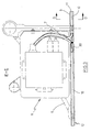
- a row of seats is supplied with data and electrical energy on the seat frame, in the A supply unit 8 is provided in the area of the seat base 6.
- 3 is the Supply unit 8 - also called connection box - shown as a detail. Data and supply lines 7 are available due to the seat providing information and entertainment options for the supply unit 8 relocate.
- the course of the cable laying in the area of a seat rail 5 can be seen in a sectional view in FIG. 4.
- the seat base 6 is fastened in the seat rail 5, as shown in dashed lines.
- a seat rail cover 9 is provided in the areas of the seat rail 5 between the rows of seats that do not accommodate any parts of the seat frame 6.
- longitudinal guide elements 10 are arranged on both sides and parallel to the seat rail 5.
- the longitudinal guide elements 10 each consist of an upper part 11 and a lower part 12.
- the upper parts 11 and lower parts 12 can be provided in standard lengths and can be assembled in a modular manner to the required lengths. They are preferably extruded parts, which enables inexpensive production.
- a plastic, preferably polyamide, can be used as the material.
- the lower part 12 or a plurality of lower parts 12 arranged one behind the other are attached to a laying path 4 on the aircraft floor 13, the cables and lines 7 are laid and the upper part 11 covers the line path 4.
- the lower part 12 of the longitudinal guide element 10 has a central web 121 and laterally spaced parallel side webs 122. A cable channel 123 is thus formed on the left and right of the central web 121.
- the upper part 11 of the longitudinal guide element 10 has a snap-in element 111 corresponding to the central web 121. Starting from the snap-in element 111, lateral cover elements 112 are provided, which serve to cover the cable channels 123 and can snap into place on the side webs 122.
- each side cover element 112 projects beyond the respective cable duct 123 and is designed to be flexible, resilient and flexible. It is thus possible to arrange one end of a floor covering 14, for example a carpet edge 15, when the lateral covering element 112 is directed outwards, ie directed away from the seat rail 5. This ensures an orderly, clean finish and the edge web 113 of the side cover element 112 holds the carpet 14 in position by appropriate design of the carpet edge 15 or prevents the carpet 14 from folding up, which at the same time eliminates a danger or trip hazard for the passengers.
- the seat rail cover 9 is in the areas that are not part of the seat frame 6 record a seat rail cover 9 arranged.
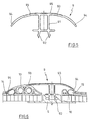
- 5 is the Seat rail cover 9 shown in a detail view.
- the seat rail cover 9 has a central part 91 with latching elements 92.
- the locking elements 92 engage in the seat rail 5 and thus hold the cover 9 in a corresponding manner Position.
- lateral covers 93 are provided, the respective edge area 94 flexibly resilient in the direction of the floor is trained.
- the middle area of the seat rail cover 9 is with a Anti-slip surface 95 provided or designed to prevent slipping to avoid going passengers.
- a Anti-slip surface 95 provided or designed to prevent slipping to avoid going passengers.
- the Edge area 94 of the cover strips of the seat rail cover 9 with the outer Shape of the upper part 11 of the longitudinal guide element 10 corresponds.
- the seat rail cover 9 at least partially covers the parallel to the seat rail 5 extending longitudinal guide elements 10, wherein the edge region 94 of the seat rail cover 9 at least partially overlaps the upper part 11 in the longitudinal direction. Because of longitudinally introduced in the upper part 11 114 between the edge region 94 of the seat rail cover 9 and the top the upper part 11 is not noticeable transition, which is a trip or Prevents snagging on the cover parts.
- the seat rail cover covers 9 after the engagement of the locking elements 92 in the seat rail 5 with a lateral Cover strip 93 a longitudinal guide element 10, as already described.
- a lateral Cover strip 93 With the other side cover strip 93 are parallel to the seat rail 5
- a flexible, flexible design of the edge regions 94 can the edge area 94 extends over the covering edge 15 and the carpet 14 Secure it against folding up or rolling up and hold it in position.
- Material for a seat rail cover 9 is a plastic, preferably polyamide, usable.
- Fig. 7 is a detail of an end cap 17 in three views seen.
- the longitudinal guide element 10 can in the end region of a cable laying path 4 be provided with such an end cap 17. Using a locking pin 171 it can be snapped into cable channels 123 by longitudinal guide elements 10 and This closes the corresponding line path (cable duct). Such one Completion prevents dirt from entering the installation path and thus protects the cables and lines to be laid 7.
- FIG. 8 is a top view of the cable laying arrangement 1 of the partial area of the cross feed.
- a connection module 22 in the area of the Dado panel i.e. the wall covering 23 in the area of the floor of a passenger cabin provides, among other things, electrical energy and signals for entertainment systems for the supply unit 8 on the corresponding passenger seating group Available.
- the connection modules 22 are provided about every fifth row of seats and appropriate cable routing to the passenger seats is necessary.
- the supply line 7 is connected via at least one longitudinal guide element 10 Area of the Dado Panel 23 to the location of the cross feed in the direction of the seat rails guided. This is followed by a cable switch 19 which either continues the line 7 in longitudinal areas or a deflection of the Line 7 to a transverse guide element 20 allows.
- the transverse guide element 20 can consist of elements with standard lengths according to the necessary length or be cut to length. Another one closes Cable switch 19, which continue at the corresponding crossing point 18 the lines or cables 7 to at least one longitudinal guide element 10 enables (an example is shown in Fig. 14).
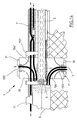
- Fig. 9 is a sectional view according to the section V-V in Fig. 8 is a longitudinal guide element 10 in the area of the side wall cladding 23 of the aircraft passenger cabin 2 shown.
- the longitudinal guide element 10 is identical to the longitudinal guide elements in the seat rail area, as shown by way of example in FIG. 4. By the use of the same components can reduce manufacturing and assembly costs be optimized. With a small number of different standard components to create a laying route according to individual requirements Cable routing can be made. It can be seen that the Lower part 12 of the longitudinal guide element 10 over the edge region of the floor element 13 protrudes and thus a transition to the side panel foot angle 23A reached. With the upper part 11, the open cable channels 123 closed after laying the cable 7.
- the edge 15 is covered by the floor covering 14 and held on the aircraft floor 13.
- the longitudinal guide elements 10 in the wall area of the passenger cabin 2 is thus in addition to the cable routing function an advantageous completion of the floor laying is achieved.
- Figs. 10 and 11 is the cable switch 19 with its two essential Components - a subsection 191 and an upper section 192 - each shown in three views.
- Fig. 10 shows the subsection 191, which for Recording of the cables and lines is provided and a transverse Recording area 193 and a longitudinal recording area 194 having.
- the cables or lines 7 can be longitudinal Recording area 194 are continued in the longitudinal direction or over the transversely extending receiving area 193 directed to a transverse guide element 20 become.
- connecting means 195 are provided which can be plugged together enable the next guide element.
- stiffening ribs 196 at the subsection 191 provided that form a stiffening area.
- a cover of the Subsection 191 is provided with top section 192, which is shown in FIG can be seen.
- the upper section 192 is to cover the longitudinal one Recording area 194 provided.
- Inner locking elements 197 and outer Locking elements 198 can be placed in corresponding holders 199 on the subsection 191 snap in and thus enable stable, tread-proof protection of the cables.
- the transverse receiving area 193 and the adjoining one Cross guide element 20 are in the installed state (see FIGS. 13 and 14) arranged below the floor covering 14, which is an additional cover this area is not necessary.
- FIG. 12 shows the transverse guide element 20 in a detail representation.
- a cross-sectional representation can be seen in FIG. 13. It is planned in the middle area of the transverse guide element 20 is a cable duct 201. Preferably through a Cover strip 203, the cable duct 201 is closed. At the side of the cable duct transition slopes 202 are provided. This is for laying in the floor area the risk of tripping for passengers is reduced. To achieve a The transition bevels 202 form sufficient tread resistance together with the side webs of the cable duct 201 and a base plate 205 a closed Triangular profile. It can be seen in FIG. 13 that the transverse guide element 20 is preferably arranged below the floor covering 14. The connection to the cable switch 19 is made possible with the connecting means 195 and 204. As well is a connection of several transverse guide elements 20 by means of the connecting means 204 provided.
- the 14 is in a cable laying arrangement 1 in the region of a seat rail 5 in shown a top view.
- the course of the cables can be seen or lines 7, 7 'starting from a cross feed from one side of the Seat rail 5 around a seat frame or seat base 6 on the other side of the Seat rail 5.
- the lines 7 and 7 ' are from the transverse receiving area 193 of the cable switch 19 added, leave the cable switch 19 on Exit of longitudinal area 194 and are below the seat rail cover 9 continued in a 180 ° turn.
- the second cable switch 19 ' divides the lines 7 and 7'.
- the line 7 is over the longitudinal Area 194 'led to a longitudinal guide element 10 which a Leading the line 7 parallel to the seat rail 5 to another row of seats allows.
- the lower parts 12 of the longitudinal guide elements 10 are made by upper parts 11 covered.
- a cover in the area of the cable switch 19 is with the Upper section 192 is provided.
Landscapes
- Engineering & Computer Science (AREA)
- Aviation & Aerospace Engineering (AREA)
- Architecture (AREA)
- Civil Engineering (AREA)
- Structural Engineering (AREA)
- Mechanical Engineering (AREA)
- Details Of Indoor Wiring (AREA)
- Installation Of Indoor Wiring (AREA)
- Seats For Vehicles (AREA)
- Insulated Conductors (AREA)
Abstract
Description
Es zeigen im einzelnen:
- Fig. 1
- eine Draufsicht auf eine Passagierkabine eines Flugzeuges mit einer Anordnung zur Verlegung von Kabeln,
- Fig. 2
- eine Darstellung einer Sitzgruppe in einer Passagierkabine in einer Ansicht von vorn,
- Fig. 3
- eine Versorgungeinheit am Sitzfuß einer Sitzgruppe gemäß Schnitt E-E der Sitzgruppendarstellung in Fig. 2,
- Fig. 4
- eine Schnittdarstellung gemäß Schnitt D-D mit der Ansicht von Kabelführungselementen im Bereich von Sitzschienen,
- Fig. 5
- eine Einzelheitdarstellung einer Sitzschienenabdeckung der Kabelverlegungsanordnung,
- Fig. 6
- Kabelführungselemente im Bereich von Sitzschienen in einer zweiten Ausführungsform,
- Fig. 7
- eine Einzelheitdarstellung einer Endkappe als Abschlusselement eines Kabelführungselementes,
- Fig. 8
- eine Draufsicht auf die Kabelverlegungsanordnung im Bereich einer Anschlusseinheit mit querverlaufenden Kabelführungselementen,
- Fig. 9
- eine Schnittdarstellung mit der Ansicht von Kabelführungselementen im Bereich der Seitenverkleidung der Passagierkabine,
- Fig. 10
- eine Einzelheitdarstellung eines Unterabschnitts einer Kabelweiche,
- Fig. 11
- eine Einzelheitdarstellung eines Oberabschnitts einer Kabelweiche,
- Fig. 12
- das querverlaufende Kabelführungselement in einer Einzelheitdarstellung,
- Fig. 13
- das querverlaufende Kabelführungselement gemäß Fig. 12 in einer Anwendungsdarstellung und
- Fig. 14
- ein Ausführungsbeispiel einer Kabelverlegungsanordnung im Bereich einer Sitzschiene.
Das Unterteil 12 des Längsführungselementes 10 weist einen Mittelsteg 121 sowie seitlich beabstandet parallel verlaufende Seitenstege 122 auf. Damit ist jeweils links und rechts des Mittelsteges 121 ein Kabelkanal 123 gebildet. Das Oberteil 11 des Längsführungselementes 10 weist ein mit dem Mittelsteg 121 korrespondierendes Einrastelement 111 auf. Ausgehend vom Einrastelement 111 sind seitliche Abdeckelemente 112 vorgesehen, die der Abdeckung der Kabelkanäle 123 dienen und an den Seitenstegen 122 einrasten können. Der Randbereich 113 jeweils eines seitlichen Abdeckelementes 112 ragt über den jeweiligen Kabelkanal 123 hinaus und ist flexibel federnd und biegsam ausgebildet. Damit ist es möglich, beim nach außen gerichteten, d.h. weg von der Sitzschiene 5 gerichteten seitlichen Abdeckelement 112 unterhalb des Randbereichs 113 ein Ende eines Fußbodenbelages 14, beispielsweise einen Teppichrand 15 anzuordnen. Damit ist ein geordneter, sauberer Abschluss erzielt und der Randsteg 113 des seitlichen Abdeckelementes 112 hält durch entsprechende Gestaltung des Teppichrandes 15 den Teppich 14 in Position oder verhindert das Hochklappen des Teppichs 14, was gleichzeitig eine Gefahren- oder Stolperstelle für die Passagiere ausschaltet. Das nach innen, d.h. zur Sitzschiene 5 hin gerichtete Abdeckelement 112 liegt mit seinem Randbereich 113 am Außenrand des Unterteils 12 an.
- 1 -
- Anordnung zur Verlegung von Kabeln
- 2 -
- Flugzeugpassagierkabine
- 21 -
- Flugzeugwand
- 22 -
- Anschlussmodul
- 23 -
- Fußverkleidung (Dado-Panel)
- 23A -
- Seitenverkleidungsfusswinkel
- 3 -
- Sitzgruppe
- 4 -
- Verlegeweg für Kabel und Leitungen
- 5 -
- Sitzschienen
- 6 -
- Sitzgestell/Sitzfuß
- 7 -
- Leitungen
- 8 -
- Versorgungseinheit (Anschlussbox)
- 9 -
- Sitzschienenabdeckung
- 91 -
- Mittelteil
- 92 -
- Rastelemente
- 93 -
- seitliche Abdeckleisten
- 94 -
- Randbereich der Abdeckleisten
- 95 -
- Antirutschfläche
- 10 -
- Längsführungselement
- 11 -
- Oberteil
- 111 -
- Einrastelement
- 112 -
- seitliche Abdeckelemente
- 113 -
- Randbereich
- 114 -
- Absetzung
- 12 -
- Unterteil
- 121 -
- Mittelsteg
- 122 -
- Seitensteg
- 123 -
- Kabelkanal
- 124 -
- Halteelemente
- 13 -
- Flugzeugfußboden
- 14 -
- Fußbodenbelag (Teppich)
- 15 -
- Teppichrand
- 16 -
- Kabelführungen
- 17 -
- Endkappe
- 171 -
- Rastzapfen
- 18 -
- Kreuzungspunkt
- 19 -
- Kabelweiche
- 191 -
- Unterabschnitt
- 192 -
- Oberabschnitt
- 193 -
- querverlaufender Aufnahmebereich
- 194 -
- längsverlaufende Bereiche
- 195 -
- Verbindungsmittel
- 196 -
- Versteifungsrippen
- 197 -
- innere Rastelemente
- 198 -
- äußere Rastelemente
- 199 -
- Halterungen
- 20 -
- Querführungselement
- 201 -
- Kabelkanal
- 202 -
- Übergangsschrägen
- 203 -
- Abdeckleisten für Kabelkanal
- 204 -
- Verbindungsmittel
- 205 -
- Bodenplatte
Claims (14)
- Anordnung zur Verlegung von Kabeln im Fußbodenbereich eines Verkehrsflugzeuges, wobei Längsführungselemente und Querführungselemente vorgesehen sind, die Kabelkanäle bilden, dadurch gekennzeichnet, dass die Längsführungselemente (10) sowie die Querführungselemente (20) jeweils aus Unterteilen (12; 201) sowie Oberteilen (11; 203) gebildet sind, die Unterteile (12; 201) auf dem Flugzeugfußboden (13) befestigt sind und die Oberteile (11; 203) an den Unterteilen (12; 201) angeordnet sind, an mindestens einem Kreuzungspunkt (18) von Längs- und Querführungselementen (10; 20) eine Kabelweiche (19) vorgesehen ist, die mit den Längs- und Querführungselementen (10; 20) einen Kabelverlegungsweg (4) bildet.
- Anordnung nach Anspruch 1, dadurch gekennzeichnet, dass
das Unterteil (12) des Längsführungselementes (10) einen Mittelsteg (121) sowie seitlich beabstandet parallel verlaufende Seitenstege (122) aufweist, die jeweils links und rechts des Mittelsteges (121) zumindest einen Kabelkanal (123) bilden, das Oberteil (11) des Längsführungselementes (10) ein mit dem Mittelsteg (121) korrespondierendes Einrastelement (111) aufweist, ausgehend vom Einrastelement (111) seitliche Abdeckelemente (112) zur Abdeckung der Kabelkanäle (123) vorgesehen sind, wobei der Randbereich (113) eines seitlichen Abdeckelementes (112) über den jeweiligen Kabelkanal (123) hinausragt und flexibel federnd biegsam ist. - Anordnung nach Anspruch 1 oder 2, dadurch gekennzeichnet, dass die Längsführungselemente (10) im wesentlichen parallel zu im Flugzeugfußboden (13) vorgesehenen Sitzschienen (5) verlaufen, wobei das nach außen gerichtete seitliche Abdeckelement (112) mit seinem Randbereich (113) oberhalb eines Fußbodenbelagrandes (15) anordenbar ist und das nach innen gerichtete Abdeckelement (112) mit seinem Randbereich (113) zur Sitzschiene (5) gerichtet ist.
- Anordnung nach einem der Ansprüche 1 bis 3, dadurch gekennzeichnet, dass oberhalb der Sitzschiene (5) eine Sitzschienenabdeckung (9) angeordnet ist, die ein Mittelteil (91) mit Rastelementen (92) aufweist, welche in die Sitzschiene (5) eingreifen, ausgehend vom Mittelteil (91) seitliche Abdeckleisten (93) vorgesehen sind, deren jeweiliger Randbereich (94) flexibel federnd in Richtung des Fußbodens (13) ausgebildet ist.
- Anordnung nach Anspruch 4, dadurch gekennzeichnet, dass der Randbereich (94) der Sitzschienenabdeckung (9) sowie die äußere Form des Oberteils (11) des Längsführungselementes (10) einander korrespondierend ausgebildet sind.
- Anordnung nach einem der Ansprüche 1 bis 5, dadurch gekennzeichnet, dass die Sitzschienenabdeckung (9) nach dem Eingreifen in die Sitzschiene (5) die parallel zur Sitzschiene (5) verlaufenden Längsführungselemente (10) zumindest teilweise abdeckt, wobei der Randbereich (94) der Sitzschienenabdeckung (9) zumindest teilweise das Oberteil (11) des Längsführungselementes (10) in Längsrichtung überlappt und in eine Absetzung (114) einfügbar ist.
- Anordnung nach einem der Ansprüche 1 bis 6, dadurch gekennzeichnet, dass die Sitzschienenabdeckung (9) nach dem Eingreifen in die Sitzschiene (5) parallel zur Sitzschiene (5) verlaufende Kabelführungen (16) und/oder Fußbodenbelagränder (15) zumindest teilweise abdeckt, wobei der Randbereich (94) der Sitzschienenabdeckung (9) sich über den Belagrand (15) erstreckt und diesen abdeckt bzw. hält.
- Anordnung nach einem der Ansprüche 1 bis 7, dadurch gekennzeichnet, dass zumindest die flexibel federnden Bereiche der Sitzschienenabdeckung (9) sowie die Oberteile (11) aus Kunststoff, vorzugsweise Polyamid bestehen.
- Anordnung nach einem der Ansprüche 1 bis 8, dadurch gekennzeichnet, dass das Längsführungselement (10) im Endbereich einer Kabelverlegungsanordnung (1) mit einer in einen Kabelkanal (123) einrastbaren Endkappe (17) versehen ist.
- Anordnung nach einem der Ansprüche 1 bis 9, dadurch gekennzeichnet, dass das Querführungselement (20) im Mittelbereich einen Kabelkanal (201) vorsieht, der seitlich angeordnete Übergangsschrägen (202) aufweist.
- Anordnung nach einem der Ansprüche 1 bis 10, dadurch gekennzeichnet, dass Verbindungsmittel (204) am Querführungselement (20) vorgesehen sind.
- Anordnung nach einem der Ansprüche 1 bis 11, dadurch gekennzeichnet, dass die Kabelweiche (19) aus einem Unterabschnitt (191) zur Aufnahme der Kabel und Leitungen und einem Oberabschnitt (192) zur Abdeckung gebildet ist, wobei an der querverlaufenden Aufnahme (193) des Unterabschnitts Verbindungsmittel (195) vorgesehen sind, die mit Verbindungsmitteln (204) des Querführungselementes (20) in Wirkverbindung stehen.
- Anordnung nach einem der Ansprüche 10 bis 12, dadurch gekennzeichnet, dass das Querführungselement (20) sowie die querverlaufende Aufnahme (193) des Unterabschnitts (191) unterhalb des Fußbodenbelags (14) anordenbar sind.
- Anordnung nach einem der Ansprüche 12 und 13, dadurch gekennzeichnet, dass der Oberabschnitt (192) als Abdeckung des längsverlaufenden Bereichs (194) vorgesehen ist, wobei Rastelemente (197, 198) an einem Versteifungsbereich (196, 199) des Unterabschnitts (191) und an Halterungen (199) im längsverlaufenden Bereich (194) des Unterabschnitts (191 ) angreifen.
Applications Claiming Priority (2)
| Application Number | Priority Date | Filing Date | Title |
|---|---|---|---|
| DE10248241 | 2002-10-16 | ||
| DE10248241A DE10248241A1 (de) | 2002-10-16 | 2002-10-16 | Anordnung zur Verlegung von Kabeln im Fußbodenbereich eines Verkehrsflugzeuges |
Publications (3)
| Publication Number | Publication Date |
|---|---|
| EP1411611A2 true EP1411611A2 (de) | 2004-04-21 |
| EP1411611A3 EP1411611A3 (de) | 2005-06-15 |
| EP1411611B1 EP1411611B1 (de) | 2007-08-22 |
Family
ID=32038724
Family Applications (1)
| Application Number | Title | Priority Date | Filing Date |
|---|---|---|---|
| EP03022073A Expired - Lifetime EP1411611B1 (de) | 2002-10-16 | 2003-10-01 | Anordnung zur Verlegung von Kabeln im Fussbodenbereich eines Verkehrsflugzeuges |
Country Status (4)
| Country | Link |
|---|---|
| US (1) | US6875916B2 (de) |
| EP (1) | EP1411611B1 (de) |
| AT (1) | ATE371286T1 (de) |
| DE (2) | DE10248241A1 (de) |
Cited By (2)
| Publication number | Priority date | Publication date | Assignee | Title |
|---|---|---|---|---|
| EP1732188A2 (de) | 2005-06-10 | 2006-12-13 | The Boeing Company | Verfahren und Vorrichtung zum fixieren einen elektrisch angetriebenen Sitzschienendeckel mit und durch der Sitzschieneneinheit |
| FR2964748A1 (fr) * | 2010-09-15 | 2012-03-16 | Airbus Operations Sas | Procede et architecture de detection d'anomalies electriques par reflectometrie |
Families Citing this family (60)
| Publication number | Priority date | Publication date | Assignee | Title |
|---|---|---|---|---|
| DE10360807B4 (de) * | 2003-12-19 | 2007-09-06 | Airbus Deutschland Gmbh | Sitzschiene |
| US7370832B2 (en) * | 2004-03-29 | 2008-05-13 | The Boeing Company | Payload to support track interface and fitting apparatus and methods |
| US7506855B2 (en) * | 2004-03-29 | 2009-03-24 | The Boeing Company | Non-protruding seat track apparatus |
| US7195201B2 (en) * | 2004-03-29 | 2007-03-27 | The Boeing Company | Adaptable payload enabling architecture |
| US7063562B2 (en) * | 2004-08-19 | 2006-06-20 | The Boeing Company | Seat power outlets integrated into floor |
| US7207523B2 (en) * | 2004-09-08 | 2007-04-24 | The Boeing Company | Seat power bus with discrete connection ports |
| US7185850B2 (en) * | 2004-09-16 | 2007-03-06 | The Boeing Company | Cut to fit powered seat track cover |
| DE102004045964B4 (de) * | 2004-09-22 | 2006-12-14 | Airbus Deutschland Gmbh | Kabelauslass-Element, Kabelauslass-Vorrichtung, Kabelauslass-Anordnung, Verfahren zum Herstellen eines Kabelauslass-Elements und Verwendung eines Kabelauslass-Elements in einem Flugzeug |
| US7191981B2 (en) * | 2004-11-08 | 2007-03-20 | The Boeing Company | Telescoping powered seat track cover |
| EP1737095B1 (de) * | 2005-06-22 | 2012-09-26 | Airbus Operations GmbH | Flexible Stromkabelrinne |
| DE102005063208A1 (de) * | 2005-12-31 | 2007-07-12 | Schott Ag | Faseroptische Vorrichtung für sekundäre Beleuchtungssysteme in Flugzeugkabinen |
| DE102006007469A1 (de) * | 2006-02-17 | 2007-08-30 | Airbus Deutschland Gmbh | Fußbodenaufbau in einem Flugzeug mit durchlaufenden Fußbodenplatten |
| FR2905037B1 (fr) * | 2006-08-18 | 2008-12-19 | Airbus France Sas | Support pour cables destine notamment a la construction aeronautique. |
| DE102006052258B4 (de) * | 2006-11-03 | 2008-09-11 | Proverum Ag | Kabelkanal |
| DE102007032233B4 (de) * | 2007-07-11 | 2014-07-10 | Airbus Operations Gmbh | Installationssystem für ein Flugzeug |
| DE102008060550B3 (de) * | 2008-12-04 | 2010-06-10 | Airbus Deutschland Gmbh | Anordnung zur Verlegung von elektrischen Kabeln im Fußbodenbereich eines Flugzeuges |
| DE102009017319A1 (de) * | 2009-04-16 | 2010-10-21 | Airbus Deutschland Gmbh | Kabelführungsvorrichtung für einen in einer Flugzeugkabine verlegten elektrischen Kabelstrang |
| DE102009019337B4 (de) * | 2009-04-30 | 2015-05-13 | Airbus Operations Gmbh | Modulare Haltevorrichtung für innerhalb eines Flugzeugrumpfs verlegte Anbauteile |
| GB201002611D0 (en) * | 2010-02-16 | 2010-03-31 | Airbus Operations Ltd | Aircraft raceway mounting and clamping apparatus |
| US9531174B2 (en) | 2012-02-28 | 2016-12-27 | Centurylink Intellectual Property Llc | Apical conduit and methods of using same |
| DE102012217808A1 (de) * | 2012-09-28 | 2014-04-03 | Lufthansa Technik Ag | Kommunikationssystem und -verfahren für ein Flugzeug |
| US9750391B2 (en) * | 2013-03-13 | 2017-09-05 | BSH Hausgeräte GmbH | Water-bearing domestic appliance, in particular domestic dish washer |
| EP2972542B1 (de) | 2013-03-15 | 2018-07-18 | Centurylink Intellectual Property LLC | Technologie für vor ort gegossene fasern |
| US10594095B2 (en) | 2013-03-15 | 2020-03-17 | Legrand Sa | Modular low profile raceway to provide power and/or data connectivity |
| US9786997B2 (en) | 2013-08-01 | 2017-10-10 | Centurylink Intellectual Property Llc | Wireless access point in pedestal or hand hole |
| US10276921B2 (en) | 2013-09-06 | 2019-04-30 | Centurylink Intellectual Property Llc | Radiating closures |
| US9780433B2 (en) | 2013-09-06 | 2017-10-03 | Centurylink Intellectual Property Llc | Wireless distribution using cabinets, pedestals, and hand holes |
| US10613284B2 (en) | 2013-10-18 | 2020-04-07 | Centurylink Intellectual Property Llc | Fiber-to-the-Premises (FTTP) methods and systems |
| US10330882B2 (en) | 2013-09-06 | 2019-06-25 | Centurylink Intellectual Property Llc | Apical radiator |
| US10154325B2 (en) | 2014-02-12 | 2018-12-11 | Centurylink Intellectual Property Llc | Point-to-point fiber insertion |
| US10578825B2 (en) | 2013-09-06 | 2020-03-03 | Centurylink Intellectual Property Llc | Apical radiator |
| US10774948B2 (en) | 2013-10-18 | 2020-09-15 | Centurylink Intellectual Property Llc | Apical filler layers |
| DE102014202288B4 (de) * | 2014-02-07 | 2023-05-17 | Airbus Operations Gmbh | Schienensystem zur Sitzmontage in einem Flugzeug |
| DE102014202287B4 (de) | 2014-02-07 | 2019-09-12 | Airbus Operations Gmbh | Schienensystem zur Sitzmontage in einem Flugzeug |
| US10015570B2 (en) | 2014-02-12 | 2018-07-03 | Centurylink Intellectual Property Llc | Touchless fiber network |
| US9896185B2 (en) * | 2014-06-23 | 2018-02-20 | Greenpoint Technologies, Inc. | Aircraft interior flooring systems |
| US9694909B2 (en) * | 2014-07-17 | 2017-07-04 | Aai Corporation | Modular mounting structure with embedded electrical bus |
| US9685730B2 (en) * | 2014-09-12 | 2017-06-20 | Steelcase Inc. | Floor power distribution system |
| DE102014222206A1 (de) | 2014-10-30 | 2016-05-04 | Airbus Operations Gmbh | Anordnung zum Verlegen von Kabeln, insbesondere von elektrischen Leitungen, in einem Luft- oder Raumfahrzeug |
| US9742172B2 (en) | 2015-01-30 | 2017-08-22 | Centurylink Intellectual Property Llc | MediaLink interconnection box |
| JP6508074B2 (ja) * | 2016-01-28 | 2019-05-08 | 株式会社オートネットワーク技術研究所 | プロテクタ付電線及びプロテクタ付電線の配設構造 |
| US10249103B2 (en) | 2016-08-02 | 2019-04-02 | Centurylink Intellectual Property Llc | System and method for implementing added services for OBD2 smart vehicle connection |
| US10110272B2 (en) | 2016-08-24 | 2018-10-23 | Centurylink Intellectual Property Llc | Wearable gesture control device and method |
| US10687377B2 (en) | 2016-09-20 | 2020-06-16 | Centurylink Intellectual Property Llc | Universal wireless station for multiple simultaneous wireless services |
| DE102016122993B4 (de) * | 2016-11-29 | 2020-01-16 | Airbus Operations Gmbh | Vorrichtung zum Führen einer Leitung im Fussboden einer Luftfahrzeugkabine |
| US10222773B2 (en) | 2016-12-23 | 2019-03-05 | Centurylink Intellectual Property Llc | System, apparatus, and method for implementing one or more internet of things (IoT) capable devices embedded within a roadway structure for performing various tasks |
| US10150471B2 (en) | 2016-12-23 | 2018-12-11 | Centurylink Intellectual Property Llc | Smart vehicle apparatus, system, and method |
| US10193981B2 (en) | 2016-12-23 | 2019-01-29 | Centurylink Intellectual Property Llc | Internet of things (IoT) self-organizing network |
| US10146024B2 (en) | 2017-01-10 | 2018-12-04 | Centurylink Intellectual Property Llc | Apical conduit method and system |
| GB2575108A (en) * | 2018-06-29 | 2020-01-01 | Airbus Operations Ltd | Aircraft cable routing system and method of installation thereof |
| DE102018119130A1 (de) * | 2018-08-07 | 2020-02-13 | Lufthansa Technik Ag | Elektronikgehäuse für Flugzeuge |
| US11180238B2 (en) * | 2018-11-19 | 2021-11-23 | The Boeing Company | Shear ties for aircraft wing |
| CN109910784A (zh) * | 2019-03-14 | 2019-06-21 | 嘉兴市盛央电气有限公司 | 卡扣式软管固定架 |
| US10862283B1 (en) * | 2019-06-06 | 2020-12-08 | FSR, Inc. | Raceway for electrical and connectivity cables |
| US11362494B2 (en) * | 2019-07-01 | 2022-06-14 | The Boeing Company | Assembly, system, and methods for installing conductive elements in an aircraft |
| US11505321B2 (en) * | 2020-06-15 | 2022-11-22 | The Boeing Company | Underfloor wire routing system for passenger cabin |
| DE102021112580A1 (de) | 2021-05-14 | 2022-11-17 | Telair International Gmbh | Frachtladeraum eines Flugzeugs mit Verkleidungselementen und mindestens einem Gehäuseelement |
| EP4124572B1 (de) * | 2021-07-29 | 2024-04-03 | KID-Systeme GmbH | Passagiersitzanordnung mit modularer energieversorgung und passagierflugzeug mit derartiger sitzanordnung |
| US11670922B2 (en) | 2021-10-29 | 2023-06-06 | Mvvp Llc | Power and/or data connectivity track system |
| US20250030231A1 (en) * | 2023-07-17 | 2025-01-23 | The Boeing Company | Electrical Raceway Installation |
Family Cites Families (15)
| Publication number | Priority date | Publication date | Assignee | Title |
|---|---|---|---|---|
| US3118017A (en) * | 1962-02-23 | 1964-01-14 | Wimbish Hilton | Receptacle for conduit |
| US4723580A (en) * | 1986-10-24 | 1988-02-09 | Trautwein Jerry B | Cable sheath assembly |
| US5523529A (en) * | 1991-03-26 | 1996-06-04 | Cable Ready, Inc. | Snap-fit protective molding assembly for electrical cables and entry tools therefor |
| ES2138782T3 (es) * | 1992-01-17 | 2000-01-16 | Wiremold Co | Un conjunto de canaleta. |
| US5336849A (en) * | 1992-01-17 | 1994-08-09 | The Wiremold Company | Raceway assembly for power and communications conductors |
| US5907936A (en) * | 1996-04-25 | 1999-06-01 | Thomas & Betts Corporation | Electrical floor hatch and wiring system for a concrete floor structure |
| US6566598B1 (en) * | 1997-04-10 | 2003-05-20 | Clinton R. Strong | Raceway for providing power and communications connectivity |
| US6367211B1 (en) * | 1997-06-05 | 2002-04-09 | Haworth, Inc. | Floor raceway for power and communications cables |
| US6448497B1 (en) * | 2000-08-21 | 2002-09-10 | Mccracken Ronald G. | Cable tray and walkway system |
| DE10112700B4 (de) * | 2001-03-16 | 2004-03-25 | Tehalit Gmbh & Co. Kg | Formteil zum Verbinden von zwei oder mehr Abschnitten eines Kabelkanals |
| US6498297B2 (en) * | 2001-04-09 | 2002-12-24 | The Boeing Company | Self-closing electrical raceway and dedicated seat track cover |
| US6674000B2 (en) * | 2001-11-07 | 2004-01-06 | The Boeing Company | Simplified interconnect for center of wide body aircraft |
| US6585189B1 (en) * | 2001-12-07 | 2003-07-01 | Inflight Canada Inc. | Under floor air cooled housing system for aircraft passenger system electrical boxes and the like |
| US6504093B1 (en) * | 2002-01-11 | 2003-01-07 | The Boeing Company | Aircraft cable raceway |
| DE10223840B4 (de) * | 2002-05-28 | 2004-04-29 | Airbus Deutschland Gmbh | Kanal-Anordnung |
-
2002
- 2002-10-16 DE DE10248241A patent/DE10248241A1/de not_active Ceased
-
2003
- 2003-10-01 DE DE50307998T patent/DE50307998D1/de not_active Expired - Lifetime
- 2003-10-01 AT AT03022073T patent/ATE371286T1/de not_active IP Right Cessation
- 2003-10-01 EP EP03022073A patent/EP1411611B1/de not_active Expired - Lifetime
- 2003-10-15 US US10/688,014 patent/US6875916B2/en not_active Expired - Lifetime
Cited By (6)
| Publication number | Priority date | Publication date | Assignee | Title |
|---|---|---|---|---|
| EP1732188A2 (de) | 2005-06-10 | 2006-12-13 | The Boeing Company | Verfahren und Vorrichtung zum fixieren einen elektrisch angetriebenen Sitzschienendeckel mit und durch der Sitzschieneneinheit |
| EP1732188A3 (de) * | 2005-06-10 | 2011-03-09 | The Boeing Company | Verfahren und Vorrichtung zum fixieren einen elektrisch angetriebenen Sitzschienendeckel mit und durch der Sitzschieneneinheit |
| US8033501B2 (en) | 2005-06-10 | 2011-10-11 | The Boeing Company | Method and apparatus for attaching electrically powered seat track cover to through hole seat track design |
| FR2964748A1 (fr) * | 2010-09-15 | 2012-03-16 | Airbus Operations Sas | Procede et architecture de detection d'anomalies electriques par reflectometrie |
| WO2012035246A1 (fr) * | 2010-09-15 | 2012-03-22 | Airbus Operations Sas | Procede et architecture de detection par reflectometrie d'anomalies electriques inaccessibles |
| US9250285B2 (en) | 2010-09-15 | 2016-02-02 | Airbus Operations (S.A.S.) | Method and architecture for detecting inaccessible electrical anomalies by means of reflectometry |
Also Published As
| Publication number | Publication date |
|---|---|
| DE10248241A1 (de) | 2004-05-06 |
| US6875916B2 (en) | 2005-04-05 |
| EP1411611A3 (de) | 2005-06-15 |
| US20040129445A1 (en) | 2004-07-08 |
| ATE371286T1 (de) | 2007-09-15 |
| DE50307998D1 (de) | 2007-10-04 |
| EP1411611B1 (de) | 2007-08-22 |
Similar Documents
| Publication | Publication Date | Title |
|---|---|---|
| EP1411611B1 (de) | Anordnung zur Verlegung von Kabeln im Fussbodenbereich eines Verkehrsflugzeuges | |
| EP1104589B1 (de) | Leitungsführungsanordnung | |
| EP0795469A1 (de) | Fluchtwegbeleuchtungs- und Leitsystem in Passagierkabinen, insbesondere für Passagierflugzeuge | |
| EP2460237B1 (de) | Anordnung zum verbinden von zwei aufeinander folgenden schleifleitungsschienen | |
| EP3237240B1 (de) | Kabelführung für wagenübergangsleitungen | |
| WO2014124914A1 (de) | Schienenfahrzeug | |
| DE102012218312B4 (de) | Sitzanordnung mit einer längenvariablen Schienenabdeckung für eine Passagierkabine eines Transportmittels und Luftfahrzeug | |
| WO2011134614A2 (de) | Versorgungssystem zur versorgung von passagieren in einem passagierraum eines fahrzeugs | |
| DE102018127019A1 (de) | Elektrisches Verbindungssystem für einen Sitz | |
| DE3603849C2 (de) | ||
| DE19911152A1 (de) | Verkabelbares Verkleidungsteil, Verfahren zur Herstellung eines solchen und Mittel dazu | |
| EP2978652B1 (de) | Fahrzeug, insbesondere schienenfahrzeug | |
| DE10052359A1 (de) | Elektrische Reihenklemme, insbesondere Mehrstockklemme | |
| EP4309248A1 (de) | Verteilungssystem für ein bordnetz sowie versorgungsstrang für ein solches verteilungssystem | |
| WO2024213668A1 (de) | Energieführungskette mit trennstegen | |
| WO2007137872A1 (de) | Montageeinheit für ein schienen-triebfahrzeug | |
| DE102005046194B4 (de) | Kabelkanal mit Kanalsegmenten | |
| EP1580858A2 (de) | Kabelhalter | |
| DE19721871C2 (de) | Anordnung von elektrischen Kabelsystemen in einem Kabelkanal zur Stromversorgung von elektrisch betriebenen Schienenfahrzeugen und Industrieanlagen | |
| DE102024125456B3 (de) | Gehäuse, beispielsweise für einen Glasfaser-Netzverteiler oder Anschlusskasten, und Verfahren zum Installieren eines Gehäuses | |
| DE102012211130A1 (de) | Bewegliche Trennwand | |
| DE102019123674A1 (de) | Verstelleinrichtung für ein Fahrzeug | |
| DE102014222206A1 (de) | Anordnung zum Verlegen von Kabeln, insbesondere von elektrischen Leitungen, in einem Luft- oder Raumfahrzeug | |
| DE102010021919A1 (de) | Leitungssystem | |
| DE29807064U1 (de) | Energieführungskette |
Legal Events
| Date | Code | Title | Description |
|---|---|---|---|
| PUAI | Public reference made under article 153(3) epc to a published international application that has entered the european phase |
Free format text: ORIGINAL CODE: 0009012 |
|
| AK | Designated contracting states |
Kind code of ref document: A2 Designated state(s): AT BE BG CH CY CZ DE DK EE ES FI FR GB GR HU IE IT LI LU MC NL PT RO SE SI SK TR |
|
| AX | Request for extension of the european patent |
Extension state: AL LT LV MK |
|
| PUAL | Search report despatched |
Free format text: ORIGINAL CODE: 0009013 |
|
| AK | Designated contracting states |
Kind code of ref document: A3 Designated state(s): AT BE BG CH CY CZ DE DK EE ES FI FR GB GR HU IE IT LI LU MC NL PT RO SE SI SK TR |
|
| AX | Request for extension of the european patent |
Extension state: AL LT LV MK |
|
| RIC1 | Information provided on ipc code assigned before grant |
Ipc: 7H 02G 3/04 A Ipc: 7H 02G 3/34 B |
|
| 17P | Request for examination filed |
Effective date: 20050622 |
|
| AKX | Designation fees paid |
Designated state(s): AT BE BG CH CY CZ DE DK EE ES FI FR GB GR HU IE IT LI LU MC NL PT RO SE SI SK TR |
|
| GRAP | Despatch of communication of intention to grant a patent |
Free format text: ORIGINAL CODE: EPIDOSNIGR1 |
|
| GRAS | Grant fee paid |
Free format text: ORIGINAL CODE: EPIDOSNIGR3 |
|
| GRAA | (expected) grant |
Free format text: ORIGINAL CODE: 0009210 |
|
| AK | Designated contracting states |
Kind code of ref document: B1 Designated state(s): AT BE BG CH CY CZ DE DK EE ES FI FR GB GR HU IE IT LI LU MC NL PT RO SE SI SK TR |
|
| REG | Reference to a national code |
Ref country code: GB Ref legal event code: FG4D Free format text: NOT ENGLISH |
|
| REG | Reference to a national code |
Ref country code: CH Ref legal event code: EP |
|
| REG | Reference to a national code |
Ref country code: IE Ref legal event code: FG4D Free format text: LANGUAGE OF EP DOCUMENT: GERMAN |
|
| REF | Corresponds to: |
Ref document number: 50307998 Country of ref document: DE Date of ref document: 20071004 Kind code of ref document: P |
|
| REG | Reference to a national code |
Ref country code: SE Ref legal event code: TRGR |
|
| GBT | Gb: translation of ep patent filed (gb section 77(6)(a)/1977) |
Effective date: 20071126 |
|
| ET | Fr: translation filed | ||
| PG25 | Lapsed in a contracting state [announced via postgrant information from national office to epo] |
Ref country code: BG Free format text: LAPSE BECAUSE OF FAILURE TO SUBMIT A TRANSLATION OF THE DESCRIPTION OR TO PAY THE FEE WITHIN THE PRESCRIBED TIME-LIMIT Effective date: 20071122 Ref country code: FI Free format text: LAPSE BECAUSE OF FAILURE TO SUBMIT A TRANSLATION OF THE DESCRIPTION OR TO PAY THE FEE WITHIN THE PRESCRIBED TIME-LIMIT Effective date: 20070822 Ref country code: NL Free format text: LAPSE BECAUSE OF FAILURE TO SUBMIT A TRANSLATION OF THE DESCRIPTION OR TO PAY THE FEE WITHIN THE PRESCRIBED TIME-LIMIT Effective date: 20070822 Ref country code: ES Free format text: LAPSE BECAUSE OF FAILURE TO SUBMIT A TRANSLATION OF THE DESCRIPTION OR TO PAY THE FEE WITHIN THE PRESCRIBED TIME-LIMIT Effective date: 20071203 |
|
| NLV1 | Nl: lapsed or annulled due to failure to fulfill the requirements of art. 29p and 29m of the patents act | ||
| REG | Reference to a national code |
Ref country code: IE Ref legal event code: FD4D |
|
| BERE | Be: lapsed |
Owner name: AIRBUS DEUTSCHLAND G.M.B.H. Effective date: 20071031 |
|
| PG25 | Lapsed in a contracting state [announced via postgrant information from national office to epo] |
Ref country code: DK Free format text: LAPSE BECAUSE OF FAILURE TO SUBMIT A TRANSLATION OF THE DESCRIPTION OR TO PAY THE FEE WITHIN THE PRESCRIBED TIME-LIMIT Effective date: 20070822 Ref country code: GR Free format text: LAPSE BECAUSE OF FAILURE TO SUBMIT A TRANSLATION OF THE DESCRIPTION OR TO PAY THE FEE WITHIN THE PRESCRIBED TIME-LIMIT Effective date: 20071123 |
|
| PG25 | Lapsed in a contracting state [announced via postgrant information from national office to epo] |
Ref country code: IE Free format text: LAPSE BECAUSE OF FAILURE TO SUBMIT A TRANSLATION OF THE DESCRIPTION OR TO PAY THE FEE WITHIN THE PRESCRIBED TIME-LIMIT Effective date: 20070822 Ref country code: MC Free format text: LAPSE BECAUSE OF NON-PAYMENT OF DUE FEES Effective date: 20071031 Ref country code: CZ Free format text: LAPSE BECAUSE OF FAILURE TO SUBMIT A TRANSLATION OF THE DESCRIPTION OR TO PAY THE FEE WITHIN THE PRESCRIBED TIME-LIMIT Effective date: 20070822 Ref country code: SK Free format text: LAPSE BECAUSE OF FAILURE TO SUBMIT A TRANSLATION OF THE DESCRIPTION OR TO PAY THE FEE WITHIN THE PRESCRIBED TIME-LIMIT Effective date: 20070822 Ref country code: PT Free format text: LAPSE BECAUSE OF FAILURE TO SUBMIT A TRANSLATION OF THE DESCRIPTION OR TO PAY THE FEE WITHIN THE PRESCRIBED TIME-LIMIT Effective date: 20080122 |
|
| REG | Reference to a national code |
Ref country code: CH Ref legal event code: PL |
|
| PLBE | No opposition filed within time limit |
Free format text: ORIGINAL CODE: 0009261 |
|
| STAA | Information on the status of an ep patent application or granted ep patent |
Free format text: STATUS: NO OPPOSITION FILED WITHIN TIME LIMIT |
|
| PG25 | Lapsed in a contracting state [announced via postgrant information from national office to epo] |
Ref country code: RO Free format text: LAPSE BECAUSE OF FAILURE TO SUBMIT A TRANSLATION OF THE DESCRIPTION OR TO PAY THE FEE WITHIN THE PRESCRIBED TIME-LIMIT Effective date: 20070822 |
|
| 26N | No opposition filed |
Effective date: 20080526 |
|
| PG25 | Lapsed in a contracting state [announced via postgrant information from national office to epo] |
Ref country code: LI Free format text: LAPSE BECAUSE OF NON-PAYMENT OF DUE FEES Effective date: 20071031 Ref country code: CH Free format text: LAPSE BECAUSE OF NON-PAYMENT OF DUE FEES Effective date: 20071031 |
|
| PG25 | Lapsed in a contracting state [announced via postgrant information from national office to epo] |
Ref country code: BE Free format text: LAPSE BECAUSE OF NON-PAYMENT OF DUE FEES Effective date: 20071031 |
|
| PG25 | Lapsed in a contracting state [announced via postgrant information from national office to epo] |
Ref country code: EE Free format text: LAPSE BECAUSE OF FAILURE TO SUBMIT A TRANSLATION OF THE DESCRIPTION OR TO PAY THE FEE WITHIN THE PRESCRIBED TIME-LIMIT Effective date: 20070822 |
|
| PG25 | Lapsed in a contracting state [announced via postgrant information from national office to epo] |
Ref country code: AT Free format text: LAPSE BECAUSE OF NON-PAYMENT OF DUE FEES Effective date: 20071001 |
|
| PG25 | Lapsed in a contracting state [announced via postgrant information from national office to epo] |
Ref country code: SI Free format text: LAPSE BECAUSE OF FAILURE TO SUBMIT A TRANSLATION OF THE DESCRIPTION OR TO PAY THE FEE WITHIN THE PRESCRIBED TIME-LIMIT Effective date: 20070822 |
|
| PG25 | Lapsed in a contracting state [announced via postgrant information from national office to epo] |
Ref country code: CY Free format text: LAPSE BECAUSE OF FAILURE TO SUBMIT A TRANSLATION OF THE DESCRIPTION OR TO PAY THE FEE WITHIN THE PRESCRIBED TIME-LIMIT Effective date: 20070822 |
|
| PG25 | Lapsed in a contracting state [announced via postgrant information from national office to epo] |
Ref country code: LU Free format text: LAPSE BECAUSE OF NON-PAYMENT OF DUE FEES Effective date: 20071001 |
|
| PG25 | Lapsed in a contracting state [announced via postgrant information from national office to epo] |
Ref country code: TR Free format text: LAPSE BECAUSE OF FAILURE TO SUBMIT A TRANSLATION OF THE DESCRIPTION OR TO PAY THE FEE WITHIN THE PRESCRIBED TIME-LIMIT Effective date: 20070822 Ref country code: HU Free format text: LAPSE BECAUSE OF FAILURE TO SUBMIT A TRANSLATION OF THE DESCRIPTION OR TO PAY THE FEE WITHIN THE PRESCRIBED TIME-LIMIT Effective date: 20080223 |
|
| REG | Reference to a national code |
Ref country code: FR Ref legal event code: CD Owner name: AIRBUS OPERATIONS GMBH Effective date: 20111118 |
|
| REG | Reference to a national code |
Ref country code: FR Ref legal event code: PLFP Year of fee payment: 13 |
|
| REG | Reference to a national code |
Ref country code: FR Ref legal event code: PLFP Year of fee payment: 14 |
|
| PGFP | Annual fee paid to national office [announced via postgrant information from national office to epo] |
Ref country code: GB Payment date: 20161020 Year of fee payment: 14 |
|
| PGFP | Annual fee paid to national office [announced via postgrant information from national office to epo] |
Ref country code: IT Payment date: 20161024 Year of fee payment: 14 Ref country code: SE Payment date: 20161019 Year of fee payment: 14 |
|
| REG | Reference to a national code |
Ref country code: FR Ref legal event code: PLFP Year of fee payment: 15 |
|
| REG | Reference to a national code |
Ref country code: SE Ref legal event code: EUG |
|
| GBPC | Gb: european patent ceased through non-payment of renewal fee |
Effective date: 20171001 |
|
| PG25 | Lapsed in a contracting state [announced via postgrant information from national office to epo] |
Ref country code: GB Free format text: LAPSE BECAUSE OF NON-PAYMENT OF DUE FEES Effective date: 20171001 |
|
| PG25 | Lapsed in a contracting state [announced via postgrant information from national office to epo] |
Ref country code: SE Free format text: LAPSE BECAUSE OF NON-PAYMENT OF DUE FEES Effective date: 20171002 |
|
| REG | Reference to a national code |
Ref country code: FR Ref legal event code: PLFP Year of fee payment: 16 |
|
| PG25 | Lapsed in a contracting state [announced via postgrant information from national office to epo] |
Ref country code: IT Free format text: LAPSE BECAUSE OF NON-PAYMENT OF DUE FEES Effective date: 20171001 |
|
| PGFP | Annual fee paid to national office [announced via postgrant information from national office to epo] |
Ref country code: DE Payment date: 20191021 Year of fee payment: 17 |
|
| PGFP | Annual fee paid to national office [announced via postgrant information from national office to epo] |
Ref country code: FR Payment date: 20191028 Year of fee payment: 17 |
|
| REG | Reference to a national code |
Ref country code: DE Ref legal event code: R119 Ref document number: 50307998 Country of ref document: DE |
|
| PG25 | Lapsed in a contracting state [announced via postgrant information from national office to epo] |
Ref country code: DE Free format text: LAPSE BECAUSE OF NON-PAYMENT OF DUE FEES Effective date: 20210501 Ref country code: FR Free format text: LAPSE BECAUSE OF NON-PAYMENT OF DUE FEES Effective date: 20201031 |