EP1411397A2 - Verfahren und Vorrichtung zur Erwärmung von Bedruckstoff und/oder Toner - Google Patents
Verfahren und Vorrichtung zur Erwärmung von Bedruckstoff und/oder Toner Download PDFInfo
- Publication number
- EP1411397A2 EP1411397A2 EP03018071A EP03018071A EP1411397A2 EP 1411397 A2 EP1411397 A2 EP 1411397A2 EP 03018071 A EP03018071 A EP 03018071A EP 03018071 A EP03018071 A EP 03018071A EP 1411397 A2 EP1411397 A2 EP 1411397A2
- Authority
- EP
- European Patent Office
- Prior art keywords
- resonator
- power distribution
- gap
- microwave
- adjustable
- Prior art date
- Legal status (The legal status is an assumption and is not a legal conclusion. Google has not performed a legal analysis and makes no representation as to the accuracy of the status listed.)
- Granted
Links
Images


Classifications
-
- H—ELECTRICITY
- H05—ELECTRIC TECHNIQUES NOT OTHERWISE PROVIDED FOR
- H05B—ELECTRIC HEATING; ELECTRIC LIGHT SOURCES NOT OTHERWISE PROVIDED FOR; CIRCUIT ARRANGEMENTS FOR ELECTRIC LIGHT SOURCES, IN GENERAL
- H05B6/00—Heating by electric, magnetic or electromagnetic fields
- H05B6/64—Heating using microwaves
- H05B6/6402—Aspects relating to the microwave cavity
-
- G—PHYSICS
- G03—PHOTOGRAPHY; CINEMATOGRAPHY; ANALOGOUS TECHNIQUES USING WAVES OTHER THAN OPTICAL WAVES; ELECTROGRAPHY; HOLOGRAPHY
- G03G—ELECTROGRAPHY; ELECTROPHOTOGRAPHY; MAGNETOGRAPHY
- G03G15/00—Apparatus for electrographic processes using a charge pattern
- G03G15/20—Apparatus for electrographic processes using a charge pattern for fixing, e.g. by using heat
- G03G15/2003—Apparatus for electrographic processes using a charge pattern for fixing, e.g. by using heat using heat
- G03G15/2007—Apparatus for electrographic processes using a charge pattern for fixing, e.g. by using heat using heat using radiant heat, e.g. infrared lamps, microwave heaters
-
- H—ELECTRICITY
- H05—ELECTRIC TECHNIQUES NOT OTHERWISE PROVIDED FOR
- H05B—ELECTRIC HEATING; ELECTRIC LIGHT SOURCES NOT OTHERWISE PROVIDED FOR; CIRCUIT ARRANGEMENTS FOR ELECTRIC LIGHT SOURCES, IN GENERAL
- H05B6/00—Heating by electric, magnetic or electromagnetic fields
- H05B6/64—Heating using microwaves
- H05B6/70—Feed lines
- H05B6/705—Feed lines using microwave tuning
-
- H—ELECTRICITY
- H05—ELECTRIC TECHNIQUES NOT OTHERWISE PROVIDED FOR
- H05B—ELECTRIC HEATING; ELECTRIC LIGHT SOURCES NOT OTHERWISE PROVIDED FOR; CIRCUIT ARRANGEMENTS FOR ELECTRIC LIGHT SOURCES, IN GENERAL
- H05B6/00—Heating by electric, magnetic or electromagnetic fields
- H05B6/64—Heating using microwaves
- H05B6/80—Apparatus for specific applications
- H05B6/802—Apparatus for specific applications for heating fluids
-
- H—ELECTRICITY
- H05—ELECTRIC TECHNIQUES NOT OTHERWISE PROVIDED FOR
- H05B—ELECTRIC HEATING; ELECTRIC LIGHT SOURCES NOT OTHERWISE PROVIDED FOR; CIRCUIT ARRANGEMENTS FOR ELECTRIC LIGHT SOURCES, IN GENERAL
- H05B2206/00—Aspects relating to heating by electric, magnetic, or electromagnetic fields covered by group H05B6/00
- H05B2206/04—Heating using microwaves
- H05B2206/046—Microwave drying of wood, ink, food, ceramic, sintering of ceramic, clothes, hair
Definitions
- the invention relates to a method for heating printing material and / or Toner, especially in an electrophotographic printing machine, with at least one with at least one hollow chamber resonator, standing microwave, the printing material through a gap of the resonator to be led.
- the invention relates to a device for heating printing material and / or toner, especially in an electrophotographic Printing machine, the at least one resonator with at least one hollow chamber for from a microwave transmitter, a microwave source or one Microwave generator comprises emitted microwaves, the at least one standing microwave generated and has a gap through which the substrate can be passed through.
- a method and a device of the aforementioned type is known from DE-A-101 45 005.
- the intensity profile of the electric field E x which runs parallel to the width extension of the printing material, is desired to be trapezoidal and almost rectangular. This can also be viewed as the power curve of the resonator in the corresponding x-direction.
- a cooling device is arranged in the region of the resonator cools the substrate so far that the temperature of the toner is below its glass transition temperature.
- the cooling device can by its Design the heating behavior of the toner-coated substrate straight in the overlap area of resonators. Becomes for example, cooling air is blown into the overlap area, and the printing material strongly cooled in this area, the fixation result can change in this area change. Also in view of this, the area of overlap less sensitive due to the flanks of the field strength curves of the resonators be designed against interference.
- the profile of the performance curve of a resonator to choose sensibly, for example, on the one hand if possible small overlap and on the other hand to achieve high process stability and ensure.
- the invention is based on the object of a method or a device of the type mentioned at the outset with regard to those described above To further improve aspects.
- the performance curve is therefore advantageous the selected resonator for the respective need, so to speak, specifically and individually designed.
- This formability makes it more independent achieved by the remaining arbitrariness when selecting a resonator, in particular also with regard to the possibility given according to the invention a certain standardization of the resonators of a formation of resonators for a fixing device. So there is no need to provide a larger one Assortment of resonators with verified, different Performance characteristics and a selection of those for the present need suitable resonators from this range.
- the performance curve is mentally broken down into characteristic areas and parameterized in some way, taking those ranges or parameters prefers certain parameters of the resonator, which are preferred further developments and embodiments of a resonator according to the invention are developed and made available to influence the course of performance be assigned.
- the power distribution should preferably be a function of the location can be set or changed, preferably primarily via the Width across the direction of the substrate guide.
- the power distribution as a function of the location can be divided into three main areas be divided.
- the three areas to be distinguished are the two areas from the wall to the center a steady, almost linearly growing power distribution have (flanks) between which there is a third area with a Power distribution is located, which is generally described as a curved curve can be.
- This curvature of the curve can be positive, negative or very be small.
- This curve is referred to as a trapezoidal shape. It can preferably be provided that the steepness of the flanks of this U-shape is set or changed.
- the power distribution as a function of the place runs essentially in the form of a trapezoid and that the curvature of the central base region of this shape is set or is changed.
- the performance profile each dynamically, i.e. varies over time, possibly even in the course of a process, to adapt to the currently prevailing needs.
- This is in particular possible because it has been recognized according to the invention that a proper Adjustment of the course of the respective power distribution in an appropriate manner Quite with relatively few parameters of the performance profile and the associated resonator is to be made possible.
- a development of the method according to the invention provides that at least one geometric size of the resonator, at least relative to at least one other geometric size of the resonator, or is changed.
- a resonator according to the invention is therefore preferably based on its geometric Parameterized conditions, for which such suitable in an inventive manner geometrical conditions proposed and for influencing of the performance profile course are assigned to the areas of this course.
- a simple solution according to the invention already consists in the width of the resonator column in other words, the clear height through which the printing material is guided change, thereby in particular the slope of the power curve to change and discontinue.
- a device according to the invention of the type mentioned initially is in an independent solution to the task in that the resonator for a power distribution that is specified and set specifically for the respective need the microwave applied by the resonator and is configured.
- the power distribution is preset or adjustable as a function of the location, preferably the power distribution is preset or adjustable across the width transversely to the direction of the substrate guide, preferably the power distribution as a function of
- the location is essentially trapezoidal and the slope of the flanks of this shape is preset or adjustable and / or the power distribution as a function of the location is essentially in the form of a trapezoid and the curvature of the central base region of this shape is preset or adjustable.
- the power distribution can be preset or set asymmetrically as a function of the location and / or that the power distribution can be varied over time or dynamically.
- the width of the gap of the resonator be preset or adjustable.
- a further development of the resonator according to the invention is characterized by this that the end face of the resonator facing away from the microwave wave entry side is closed by a chamber ceiling, which has a recess, which extends in a direction parallel to the guide direction of the Has printing material, preferably the recess is approximately in the form of a trench extends from one chamber wall to the other in the ceiling.
- the depth of the depression is preset or adjustable and / or that the width of an edge or several edges of the depression transverse to the direction of the guidance of the printing material is or are preset or adjustable.
- Another development of the invention is characterized in that the as seen from the microwave entrance into the hollow chamber on the other side of the gap Hollow chamber area at least one directed inward into the hollow chamber Has collar edge as a boundary surface section for the gap and / or that seen from the microwave entry into the hollow chamber on this side from the gap arranged hollow chamber area at least one inwards into the Hollow chamber facing collar edge as a boundary surface section for the Has gap.
- This collar edge can advantageously be carried out so that the collar edge is only present on the boundary surfaces that are parallel to the direction of transport of the printed material.
- the hollow chamber at least Partially dividing into chamber areas has a partition section that is parallel runs to the guide direction of the printing material, preferably the partition section at least on one side parallel to the management level of the Substrate-oriented aperture (or at least a fragmentary one has a protruding balcony that acts as a diaphragm limitation) and preferably the distance of the screen (or the balcony) from the to the gap facing edge of the partition section is preset or adjustable or are about the curvature of the course of the power distribution of the resonator.
- that part of the microwave source preferably faces Resonators by at least one partition section in at least two Hollow chamber areas can also be divided according to a further development the invention provide that a separate one at the chamber areas Microwave source is connected or that to the chamber areas common microwave source is connected to supply the chamber areas has a power splitter.
- the common microwave source with the power splitter that covers the chamber areas is supplied by splitting the microwave source power the safer solution than ensuring that both chamber areas with the exact same microwave frequency are supplied. This is e.g. at a wide TE101 resonator important, preferably according to the invention as an applicator is used.
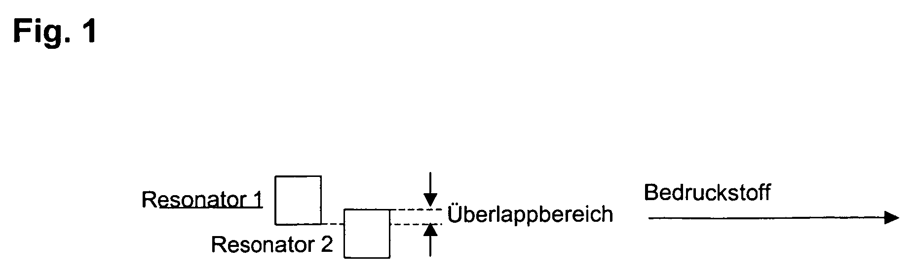
- Fig. 1 shows a schematic plan view of two examples in the direction of transport successively staggered resonators 1 and 2 in known per se Wise.
- Fig. 2 shows a diagram as a function of the transverse to the direction of transport Substrate measured temperature profile, and that dashed Temperature profile, which is generated by the first resonator 1 alone, dash-dotted the temperature profile that generated by the second resonator 2 alone is and pulled through the temperature profile, the two resonators 1 and 2 is generated together.
- the actual overlap of the temperature profiles of the two resonators 1 and 2 cannot be seen in FIG. 1 for reasons of scale, since the temperature profiles are only below the selected local axis the coordinate cross, drawn at a temperature value of about 80 ° C instead of crossing at 0 ° C, namely at about 55 ° C.
- FIG. 1 shows so only the top of the temperature profiles.
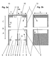
- a TE101 applicator is proposed, as shown in more detail in FIGS. 3a and b 3 a in a section with a viewing direction in the guide direction of the substrate and in Fig. 3b in a section with the cutting plane in the guide direction of the printing material along the line designated IIIb in FIG. 3a, dash-dotted line.
- the resonator shown in FIGS. 3a and b is in two parts, an upper one Part 1 and a lower part 2 divided, between which there is a gap 3, by the substrate is heated.
- the microwave energy is fed into the resonator from below through two openings 4 with two microwave sources of the same frequency or with a microwave source that is connected to both openings 4 and their Energy via a so-called power splitter on both chamber areas 5 of the Distributed resonators, as seen from the microwave entrance into the hollow chamber hollow chamber region arranged on this side of the gap 3 by at least a partition section 6 is at least partially divided and parallel to Guide direction of the substrate runs.
- the partition section 6 has at least on one side parallel to the guide level of the printing material through the gap 3 oriented, protruding "balcony 7", which preferably each Part of an aperture 8 which leaves open for the entry of the microwave energy Aperture 9 is.
- the side facing away from the microwave wave entry side End surface of the resonator is closed by a chamber ceiling 11 which apparently has a recess 12 which extends parallel to one another has to the direction of the substrate, with the recess about in the form of a trench in the ceiling 11 from a chamber wall 13 to other stretches.
- the depth J of the "depression 12" is preset or adjustable, as is the width I. one or more edges of the recess 12 transverse to the direction of Guide of the printing material is or are preset or adjustable.
- the microwave entry into the hollow chamber seen hollow space of the resonator part arranged beyond the gap 3 1 at least one collar edge directed into the hollow chamber has as a boundary surface section for the gap 3 and / or that the seen from the microwave entry into the hollow chamber on this side of the gap
- Hollow chamber region of the resonator part 2 at least one inwards the hollow chamber directed collar edge as a boundary surface section for has the gap 3, where all the collar edges mentioned have dimension H, which is preset or adjustable.
- FIGS. 3 a or b Further dimension designations A, B, C D, E are given in FIGS. 3 a or b, where A is the measure of the distance between the aperture 9 and the gap 3, B is the Height of the gap 3 itself, C is the distance between the gap 3 and the inner surface the recess 12, D is the distance of the central axis of the resonator (dash-dotted line IIIb) from the inside of a chamber wall 13 and E is the internal dimension (length) of the cavity of the resonator.
- a preferred embodiment of the resonator according to the invention is to be dimensioned using the dimensions from the following Table 1 using these dimensional designations.
- a 37 mm B 6 mm C 35 mm D 50 mm e 92 mm G 0-10 mm H 0-10 mm I 0-50 mm J 0-20 mm
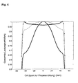
- the size H the steepness of the edges of the course of a power distribution can be changed and about the sizes I and J, the curvature of the power curve in its middle range can be influenced. This is illustrated in more detail with the aid of FIG. 4 and explained.
- FIG. 4 shows in a graph the change in the profile of the power distribution of the resonator acc. Fig. 3 as a function of the location transverse to the direction of guidance of the printing material, ie in the same direction as Fig. 3a, on one standardized scale.
- a thick, solid line is shown as an example, a dashed line and a dotted line.
- the profile changes in this case by changing the dimension I of the resonator from FIG. 3 in accordance with Table 2 below.
- FIG. 5 shows, in the manner of FIG. 4, an almost perfect rectangular profile of a power distribution of a resonator according to FIG. 3. This special case is achieved by dimensioning the resonator with the values from Table 3 below.
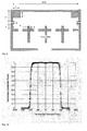
- FIG. 6 shows a schematic sectional view of a simple, known per se Hollow chamber resonator in the direction of view and in the manner of the representation of FIG. 3a.
- the resonator shown in FIG. 6 again consists of two parts 1 and 2, through a gap 3 to carry out the printing material from each other are separated.
- a microwave source can be connected to an aperture 8 from below be connected.
- N denotes the width of the resonator transversely to the guide direction of the printing material, M the height of part 1, K the height of part 2 and L the height of the gap.
- the power distribution profile of this resonator can now be influenced by varying the gap height L. If dimensions K, L, M and N are selected or changed, for example in accordance with Table 4 below, there are variations in the profile mentioned in accordance with FIG. 7 in the manner of the representation in FIGS. 4 and 5.
- Fig. 7 are the profile profiles with a dash-dotted line, an example dashed line and a solid line for gap heights or widths L equal to 10 mm, equal to 5 mm or equal to 1.5 mm and the other dimensions Table 4 shown.
- the profile of the power distribution can also be used to design the gap width assume an asymmetrical shape.
- a vertical is conceivable for the transport direction of the substrate continuously changing gap width, see above that the profile on the side with the larger gap width is correspondingly flatter runs as the profile on the side with the smaller gap width. This can go so far be guided that the positioned in the path for the substrate on the outside Resonator on the outer side is completely closed, which is advantageous both for less radiation to the outside as well as for a steeper one Profile increase on the closed side is.
- the width of the resonators Is a required certain maximum width of substrate for the fuser, the Width of the individual resonators taking into account different ones Boundary conditions can be chosen freely.
- the arrangement of the resonators plays along and across the transport direction almost no role for the substrate.
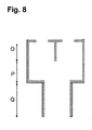
- FIG. 3a in FIG. 8 The sectional view of such a power splitter is suitable as an example the resonator according to FIG. 3a in FIG. 8, to which the one shown Powersplitter is applied from below in the area of the openings 4.
- the microwave source itself is in turn attached to the bottom of the power splitter.
- O, P and Q indicate height sections of the power splitter, which can be dimensioned, for example, according to Table 5 below.
- the maximum is Width N limited by the TE101 mode. If the width is too large, there are others Modes spread and the warming profile is no longer maintained and takes on unfavorable forms. Therefore, when growing Wide range of other design measures are taken to the TE101 mode continue to maintain in the resonator.
- FIG. 3 An embodiment for a larger width is possible according to FIG. 3.
- the width of the individual resonators corresponds to the marked parameter D.
- a version with an even wider width of the TE 101 cavity areas is shown in Fig. 9. It can be seen that there are four Areas of width D are interconnected. With the correct choice of the geometric The dimensions of the power distribution can be analogous to the previous one Be described.
- the power distributor (powersplitter) must be adjusted in addition to the geometric optimization so that the same power is available at the respective aperture openings.
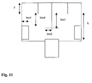
- the power splitter in FIG. 11 is mentioned as an example for the resonator shown in FIG. 9. This power splitter has the following dimensions according to table 7: L 58 mm I ' 28 mm LMS1 28.8 mm LMS2 35 mm LMS3 32.5 mm Lms4 25 mm
- width D is added and this also over the above Larger opening coupled together and combined are.
- the width must always be in the transport direction of the substrate but not kept constant, but can vary in this direction and thus create advantageous warming profiles.
- the width of the different resonators can be varied can also be chosen differently.
- a good arrangement results if the side edge of the Substrate is only ever transported through a resonator, even if the position of the edge is different.
- f r must be kept constant with these changes. This means that when the length (E) changes, the height (A + B + C) changes automatically. Suitable sizes of the parameter E are between 30 and 200 mm, preferably in the range between 60 and 100 mm.
Landscapes
- Physics & Mathematics (AREA)
- Electromagnetism (AREA)
- General Physics & Mathematics (AREA)
- Constitution Of High-Frequency Heating (AREA)
- Fixing For Electrophotography (AREA)
Abstract
Description
Auch im Hinblick auf die erfindungsgemäße Vorrichtung kann aber alternativ vorgesehen sein, daß die Leistungsverteilung als Funktion des Ortes asymmetrisch voreingestellt oder einstellbar ist und / oder daß die Leistungsverteilung zeitlich bzw. dynamisch variierbar ist.
- Fig. 1
- eine schematische Draufsicht auf zwei beispielhaft in Transportrichtung hintereinander gestaffelt angeordneter Resonatoren in an sich bekannter Weise,
- Fig. 2
- ein sich mit den beiden Resonatoren aus Fig. 1 ergebendes, beispielhaftes Temperaturprofil in an sich bekannter Weise,
- Fig. 3a
- einen Schnitt durch einen erfindungsgemäßen Resonator quer zur Führungsrichtung des Bedruckstoffes und mit Blickrichtung in die Führungsrichtung,
- Fig. 3b
- einen Schnitt durch den Resonator gemäß Fig. 3a quer zur Schnittebene In Fig. 3a,
- Fig. 4
- beispielhafte Verläufe der Leistungsverteilung eines Resonators gemäß Fig. 3a und 3b als Funktion des Ortes und bei Abmessungen des Resonators gemäß Tabelle 2,
- Fig. 5
- ein Leistungsverlauf ähnlich wie in Fig. 4, hier speziell in möglichst rechteckiger Form mit Abmessungen des Resonators gemäß Tabelle 3,
- Fig. 6
- ein schematischer Schnitt durch einen einfachen, an sich bekannten Hohlkammerresonator mit Abmessungen gemäß Tabelle 4 zur Verdeutlichung und Erklärung der Effekte bei erfindungsgemäßer Veränderung der Breite bzw. Höhe eines den Resonator teilenden Spaltes im Zusammenhang mit Fig. 7,
- Fig. 7
- beispielhafte Verläufe von Leistungsverteilungen als Funktion des Ortes bei Änderung der Spaltbreite des Resonators gemäß Fig. 6 und
- Fig. 8
- einen Schnitt durch einen Leistungsverteiler, passend zur Schnittansicht des Resonators gemäß Fig. 3a,
- Fig. 9
- einen Schnitt durch einen Resonator mit breiterer Wechselwirkungszone,
- Fig. 10
- beispielhaft einen Verlauf von Leistungsverteilung als Funktion des Ortes und
- Fig. 11
- einen zum breiteren Resonator optimierten Leistungsverteiler.
| A | 37 mm |
| B | 6 mm |
| C | 35 mm |
| D | 50 mm |
| E | 92 mm |
| G | 0-10 mm |
| H | 0-10 mm |
| I | 0-50 mm |
| J | 0-20 mm |
| Abmessungen des Resonators (mm) | H | I | J | Linienstil |
| 2 | 5 | 15 | Punkte | |
| 2 | 10 | 15 | Gestrichelt | |
| 2 | 25 | 15 | Dicke Linie |
| A | 37 mm |
| B | 6 mm |
| C | 35 mm |
| D | 50 mm |
| E | 92 mm |
| F | 0.1 mm |
| G | 10 mm |
| H | 2 mm |
| I | 6 mm |
| J | 17 mm |
| K | 37 mm |
| L | 1-10 mm |
| M | 35 mm |
| N | 52 mm |
- Verdrehen des Applikators in der Papierebene. In Prozeßrichtung ist das Profil des elektrischen Feldes im Resonator in etwa eine halbe Sinusschwingung. Daher würde das Erwärmungsprofil eines Resonators mit Rechteckprofil sich bei einer Drehung an den Flanken immer mehr abflachen.
- Es ist auch denkbar zwei Resonatoren mit unterschiedlicher Breite hintereinander anzuordnen, so daß sich zwei unterschiedlich erwärmte Bereiche ergeben.
- Einführung einer beweglichen, nicht absorbierenden dielektrischen Last (z.B. aus PTFE [Polytetrafluorethylen]). Diese Last führt zu einer Veränderung der Feldverteilung in ihrer unmittelbaren Nähe. Wird diese Last nun in die Nähe des Spalts 3 gebracht, so kann das Feldprofil ebenfalls verändert werden.
| O | 30 mm |
| P | 30 mm |
| Q | 30 mm |
| A | 35 mm |
| B | 15 mm |
| C | 33 mm |
| D | 49.5 mm |
| E | 92 mm |
| G | 6 mm |
| H | 4.5 mm |
| I | 6 mm |
| J | 17 mm |
| L | 58 mm |
| I' | 28 mm |
| Lms1 | 28.8 mm |
| Lms2 | 35 mm |
| Lms3 | 32.5 mm |
| Lms4 | 25 mm |
Claims (33)
- Verfahren zur Erwärmung von Bedruckstoff und / oder Toner, insbesondere in einer elektrofotographisch arbeitenden Druckmaschine, mit wenigstens einer mit wenigstens einem Hohlkammerresonator ausgebildeten, stehenden Mikrowelle, wobei der Bedruckstoff durch einen Spalt des Resonators geführt wird,
dadurch gekennzeichnet, dass die Leistungsverteilung der vom Resonator applizierten Mikrowelle gezielt für den jeweiligen Bedarf ausgeformt oder konfiguriert wird. - Verfahren nach Anspruch 1, dadurch gekennzeichnet, dass die Leistungsverteilung als Funktion des Ortes eingestellt oder verändert wird.
- Verfahren nach Anspruch 2, dadurch gekennzeichnet, dass die Leistungsverteilung über die Breite quer zur Richtung der Bedruckstofführung eingestellt oder verändert wird.
- Verfahren nach Anspruch 2 oder 3, dadurch gekennzeichnet, dass die Leistungsverteilung als Funktion des Ortes im wesentlichen in drei Bereiche eingeteilt wird, nämlich in zwei Bereiche von einer Wand des Resonators zur Mitte hin, in denen die Leistung stetig zunimmt (Flanke) und zwischen denen ein Bereich liegt, dessen Form einer mehr oder weniger gekrümmten Kurve folgt, derart, daß sich im wesentlichen eine Trapez-Form ergibt, und dass die Steilheit der Flanken eingestellt oder verändert wird.
- Verfahren nach einem der Ansprüche 2 bis 4, dadurch gekennzeichnet, dass die Leistungsverteilung als Funktion des Ortes im wesentlichen in Form eines Trapez verläuft und dass die Krümmung des mittleren Basisbereiches dieses Trapez eingestellt oder verändert wird, insbesondere in ihrer positiven (konvexen) oder negativen (konkaven) Krümmung oder für ein Fehlen einer solchen Krümmung (Verflachung)
- Verfahren nach Anspruch 4 und 5, dadurch gekennzeichnet, dass als Verlauf der Leistungsverteilung im wesentlichen etwa eine Rechteckform (Π-Form) eingestellt wird.
- Verfahren nach Anspruch 2 oder 3, dadurch gekennzeichnet, dass die Leistungsverteilung als Funktion des Ortes asymmetrisch zur Mittelachse eingestellt wird.
- Verfahren nach einem oder mehreren der vorhergehenden Ansprüche, dadurch gekennzeichnet, dass die Leistungsverteilung zeitlich variiert wird.
- Verfahren nach einem oder mehreren der vorhergehenden Ansprüche, dadurch gekennzeichnet, dass wenigstens eine geometrische Größe des Resonators, zumindest relativ zu wenigstens einer anderen geometrischen Größe des Resonators, eingestellt oder verändert wird.
- Verfahren nach Anspruch 9, dadurch gekennzeichnet, dass die Breite des Spaltes des Resonators eingestellt oder verändert wird.
- Vorrichtung zur Erwärmung von Bedruckstoff und / oder Toner, insbesondere in einer elektrofotographisch arbeitenden Druckmaschine, die wenigstens einen Resonator mit wenigstens einer Hohlkammer für von einem Mikrowellensender, einer Mikrowellenquelle oder einem Mikrowellengenerator ausgesandte Mikrowellen umfaßt, der wenigstens eine stehende Mikrowelle erzeugt und einen Spalt aufweist, durch den der Bedruckstoff hindurchführbar ist,
dadurch gekennzeichnet, dass der Resonator für eine gezielt für den jeweiligen Bedarf vorgegebene und eingestellte Leistungsverteilung der vom Resonator applizierten Mikrowelle konzeptioniert und konfiguriert ist. - Vorrichtung nach Anspruch 11, dadurch gekennzeichnet, dass die Leistungsverteilung als Funktion des Ortes voreingestellt oder einstellbar ist.
- Vorrichtung nach Anspruch 12, dadurch gekennzeichnet, dass die Leistungsverteilung über die Breite quer zur Richtung der Bedruckstofführung voreingestellt oder einstellbar ist.
- Vorrichtung nach Anspruch 11 oder 12, dadurch gekennzeichnet, dass die Leistungsverteilung als Funktion des Ortes in drei Bereiche eingeteilt ist, nämlich in zwei Bereiche von einer Wand des Resonators zur Mitte hin, in denen die Leistung stetig zunimmt (Flanke) und zwischen denen ein Bereich liegt, dessen Form einer mehr oder weniger gekrümmten Kurve folgt , derart, daß sich im wesentlichen eine Trapez-Form ergibt, und daß die Steilheit der Flanken dieser Form voreingestellt oder einstellbar ist.
- Vorrichtung nach einem der Ansprüche 11 bis 13, dadurch gekennzeichnet, dass die Leistungsverteilung als Funktion des Ortes im wesentlichen in Form eines Trapezes verläuft und dass die Krümmung des mittleren Basisbereiches dieser Form, insbesondere als negative oder positive Krümmung oder Verflachung, voreingestellt oder einstellbar ist.
- Vorrichtung nach Anspruch 14 und 15, dadurch gekennzeichnet, dass als Verlauf der Leistungsverteilung im wesentlichen etwa eine Rechteckform (Π-Form) voreingestellt oder einstellbar ist.
- Vorrichtung nach Anspruch 12 oder 13, dadurch gekennzeichnet, dass die Leistungsverteilung als Funktion des Ortes asymmetrisch voreingestellt oder einstellbar ist.
- Vorrichtung nach einem oder mehreren der Ansprüche 11 bis 17, dadurch gekennzeichnet, dass die Leistungsverteilung zeitlich variierbar ist.
- Vorrichtung nach einem oder mehreren der Ansprüchen11 bis 18, dadurch gekennzeichnet, dass wenigstens eine geometrische Größe des Resonators, zumindest relativ zu wenigstens einer anderen geometrischen Größe des Resonators, voreingestellt oder einstellbar ist.
- Vorrichtung nach Anspruch 19, dadurch gekennzeichnet, dass die Breite des Spaltes des Resonators voreingestellt oder einstellbar ist.
- Vorrichtung nach Anspruch 19 oder 20, dadurch gekennzeichnet, dass die der Mikrowellenwelleneintrittsseite abgewandte Endfläche des Resonators durch eine Kammerdecke verschlossen ist, die eine Vertiefung aufweist, welche eine Erstreckung in Richtung parallel zur Führungsrichtung des Bedruckstoffes hat.
- Vorrichtung nach Anspruch 21, dadurch gekennzeichnet, dass sich die Vertiefung etwa in Form eines Grabens in der Decke von einer Kammerwand bis zur anderen erstreckt.
- Vorrichtung nach Anspruch 21 oder 22, dadurch gekennzeichnet, dass die Tiefe der Vertiefung voreingestellt oder einstellbar ist.
- Vorrichtung nach einem der Ansprüche 21 bis 23, dadurch gekennzeichnet, dass die Breite eines Randes oder mehrerer Ränder der Vertiefung quer zur Richtung der Führung des Bedruckstoffes voreingestellt oder einstellbar ist oder sind.
- Vorrichtung nach einem der Ansprüche 11 bis 24, dadurch gekennzeichnet, dass der vom Mikrowelleneintritt in die Hohlkammer gesehen jenseitig vom Spalt angeordnete Hohlkammerbereich wenigstens einen einwärts in die Hohlkammer gerichteten Kragenrand als Begrenzungsflächenabschnitt für den Spalt aufweist.
- Vorrichtung nach einem der Ansprüche 11 bis 25, dadurch gekennzeichnet, dass der vom Mikrowelleneintritt in die Hohlkammer gesehen diesseitig vom Spalt angeordnete Hohlkammerbereich wenigstens einen einwärts in die Hohlkammer gerichteten Kragenrand als Begrenzungsflächenabschnitt für den Spalt aufweist.
- Vorrichtung nach Anspruch 25 oder 26, dadurch gekennzeichnet, dass die Breite eines Kragenrandes oder mehrerer Kragenränder quer zur Richtung der Führung des Bedruckstoffes voreingestellt oder einstellbar ist o-der sind.
- Vorrichtung nach einem der Ansprüche 11 bis 27, dadurch gekennzeichnet, dass der vom Mikrowelleneintritt in die Hohlkammer gesehen diesseitig vom Spalt angeordnete Hohlkammerbereich wenigstens einen die Hohlkammer wenigstens teilweise in Kammerbereiche teilenden Trennwandabschnitt aufweist, der parallel zur Führungsrichtung des Bedruckstoffes verläuft.
- Vorrichtung nach Anspruch 28, dadurch gekennzeichnet, dass an die Kammerbereiche jeweils eine separate Mikrowellenquelle angeschlossen ist.
- Vorrichtung nach Anspruch 28, dadurch gekennzeichnet, dass an die Kammerbereiche eine gemeinsame Mikrowellenquelle angeschlossen ist, die zur Versorgung der Kammerbereiche über einen Leistungsaufteiler (Powersplitter) verfügt.
- Vorrichtung nach einem der Ansprüche 28 bis 30, dadurch gekennzeichnet, dass der Trennwandabschnitt wenigstens an einer Seite eine parallel zur Führungsebene des Bedruckstoffes durch den Spalt orientierte Blende aufweist.
- Vorrichtung nach Anspruch 31, dadurch gekennzeichnet, dass der Abstand der Blende von der zum Spalt weisenden Kante des Trennwandabschnittes voreingestellt oder einstellbar ist oder sind.
- Vorrichtung nach einem oder mehreren der vorhergehenden Ansprüche, dadurch gekennzeichnet, dass als Resonator ein sogenannter TE101-Applikator vorgesehen ist.
Applications Claiming Priority (4)
| Application Number | Priority Date | Filing Date | Title |
|---|---|---|---|
| DE10247798 | 2002-10-14 | ||
| DE10247798 | 2002-10-14 | ||
| DE10335024A DE10335024A1 (de) | 2002-10-14 | 2003-07-31 | Verfahren und Vorrichtung zur Erwärmung von Bedruckstoff und/oder Toner |
| DE10335024 | 2003-07-31 |
Publications (3)
| Publication Number | Publication Date |
|---|---|
| EP1411397A2 true EP1411397A2 (de) | 2004-04-21 |
| EP1411397A3 EP1411397A3 (de) | 2006-05-10 |
| EP1411397B1 EP1411397B1 (de) | 2009-03-25 |
Family
ID=32043967
Family Applications (1)
| Application Number | Title | Priority Date | Filing Date |
|---|---|---|---|
| EP03018071A Expired - Lifetime EP1411397B1 (de) | 2002-10-14 | 2003-08-08 | Verfahren und Vorrichtung zur Erwärmung von Bedruckstoff und/oder Toner |
Country Status (2)
| Country | Link |
|---|---|
| US (1) | US7022954B2 (de) |
| EP (1) | EP1411397B1 (de) |
Cited By (2)
| Publication number | Priority date | Publication date | Assignee | Title |
|---|---|---|---|---|
| WO2006010467A1 (en) * | 2004-07-29 | 2006-02-02 | Eastman Kodak Company | Microwave heating device |
| US8664574B2 (en) | 2009-01-16 | 2014-03-04 | Krones Ag | Resonator unit, expansion process and apparatus for heating containers |
Families Citing this family (1)
| Publication number | Priority date | Publication date | Assignee | Title |
|---|---|---|---|---|
| US7515859B2 (en) * | 2007-04-24 | 2009-04-07 | Eastman Kodak Company | Power splitter for a microwave fuser of a reproduction apparatus |
Family Cites Families (10)
| Publication number | Priority date | Publication date | Assignee | Title |
|---|---|---|---|---|
| BE776652A (fr) * | 1970-12-31 | 1972-04-04 | Soulier Joel H A | Dispositif pour l'uniformisation de l'energie d'hyperfrequence appliquee a une bande ou feuille a traiter a partir d'un cavite resonnante |
| US3851131A (en) * | 1973-06-28 | 1974-11-26 | Canadian Patents Dev | Multimode microwave cavities for microwave heating systems |
| SE378057B (de) * | 1974-02-22 | 1975-08-11 | Stiftelsen Inst Mikrovags | |
| JPS5371340A (en) * | 1976-12-08 | 1978-06-24 | Hitachi Ltd | Dielectirc heater |
| US4435072A (en) * | 1980-12-11 | 1984-03-06 | Canon Kabushiki Kaisha | Image recording apparatus with leakage preventing microwave fixing device |
| US4625088A (en) * | 1985-11-07 | 1986-11-25 | Gics Paul W | Center wall with sloped ends for a microwave heat applicator |
| FR2659518B1 (fr) * | 1990-03-07 | 1992-06-12 | Microondes Syst Sa | Dispositif applicateur d'ondes hyperfrequences pour le traitement de produits en feuille ou en nappe. |
| DE10145005C2 (de) * | 2000-12-22 | 2003-08-14 | Nexpress Solutions Llc | Verfahren und Einrichtung zur Fixierung von Toner auf einem Träger bzw. einem Bedruckstoff |
| DE10145002B8 (de) * | 2000-12-22 | 2006-12-28 | Eastman Kodak Co. | Verfahren und Einrichtung zur Fixierung von Toner auf einem Träger bzw. einem Bedruckstoff |
| US6938358B2 (en) * | 2002-02-15 | 2005-09-06 | International Business Machines Corporation | Method and apparatus for electromagnetic drying of printed media |
-
2003
- 2003-08-08 EP EP03018071A patent/EP1411397B1/de not_active Expired - Lifetime
- 2003-09-17 US US10/664,510 patent/US7022954B2/en not_active Expired - Fee Related
Cited By (3)
| Publication number | Priority date | Publication date | Assignee | Title |
|---|---|---|---|---|
| WO2006010467A1 (en) * | 2004-07-29 | 2006-02-02 | Eastman Kodak Company | Microwave heating device |
| US7912414B2 (en) | 2004-07-29 | 2011-03-22 | Eastman Kodak Company | Microwave and electromagnetic printing agent heating device |
| US8664574B2 (en) | 2009-01-16 | 2014-03-04 | Krones Ag | Resonator unit, expansion process and apparatus for heating containers |
Also Published As
| Publication number | Publication date |
|---|---|
| EP1411397B1 (de) | 2009-03-25 |
| US20040226942A1 (en) | 2004-11-18 |
| US7022954B2 (en) | 2006-04-04 |
| EP1411397A3 (de) | 2006-05-10 |
Similar Documents
| Publication | Publication Date | Title |
|---|---|---|
| DE2857473C2 (de) | ||
| DE3635961A1 (de) | Induktive heizeinrichtung | |
| DE69118121T2 (de) | Quadrupolmassenspektrometers | |
| DE1952987A1 (de) | Hohlleiter | |
| EP2044968A1 (de) | Flüssigkeitsverdampfer | |
| EP0715019B1 (de) | Verfahren und Vorrichtung zum Behandeln einer Materialbahn | |
| DE102014219016B4 (de) | Verfahren zum Steuern eines Stehwellenbeschleunigers | |
| DE60100765T2 (de) | Verfahren und Vorrichtung zum Konservieren von Nahrungsmitteln in einem gepulsten elektrischen Feld | |
| DE69512601T2 (de) | Lichtstrahler | |
| DE3045603C2 (de) | Verfahren und Vorrichtung zum Ziehen eines dünnen Glasfilmes | |
| DE2162727A1 (de) | Vorrichtung zur Vergleichmäßigung der an ein Band oder Blatt von einem Hohlraumresonator aus angelegten Hyperfrequenzenergie | |
| EP3293455B1 (de) | Gasbrenner | |
| DE3427639A1 (de) | Verfahren und vorrichtung zum biegen laenglicher werkstuecke, insbesondere rohre | |
| EP1066666A1 (de) | Laser mit einer einrichtung zur veränderung der verteilung der intensität des laserlichtes über den laserstrahlquerschnitt | |
| EP0071243A2 (de) | Verfahren und Vorrichtung zum Korrigieren der Ausrichtung eines Elektronenstrahles | |
| DE102012222469B4 (de) | Diffusionsgekühlte Gaslaseranordnung und Verfahren zur Einstellung der Entladungsverteilung bei einer diffusionsgekühlten Gaslaseranordnung | |
| DE10210936C1 (de) | Verfahren für das Befestigen von Toner an einem Bedruckstoff und Mikrowelleneinrichtung | |
| EP1411397A2 (de) | Verfahren und Vorrichtung zur Erwärmung von Bedruckstoff und/oder Toner | |
| DE3815209C2 (de) | ||
| DE10335024A1 (de) | Verfahren und Vorrichtung zur Erwärmung von Bedruckstoff und/oder Toner | |
| EP1275776B1 (de) | Kalander und Verfahren zum Anordnen von Walzen in einem Walzenstapel eines Kalanders | |
| DE69213631T2 (de) | Schussfadeneintragsvorrichtung in eine düsenwebmaschine | |
| DE3416196C2 (de) | ||
| EP0283859B1 (de) | Spulenanordnung, Verfahren zur Herstellung von Spulenpaaren sowie Vorrichtung zur Herstellung von Spulenpaaren | |
| DE60208920T2 (de) | Mikrowellenapplikator |
Legal Events
| Date | Code | Title | Description |
|---|---|---|---|
| PUAI | Public reference made under article 153(3) epc to a published international application that has entered the european phase |
Free format text: ORIGINAL CODE: 0009012 |
|
| AK | Designated contracting states |
Kind code of ref document: A2 Designated state(s): AT BE BG CH CY CZ DE DK EE ES FI FR GB GR HU IE IT LI LU MC NL PT RO SE SI SK TR |
|
| AX | Request for extension of the european patent |
Extension state: AL LT LV MK |
|
| RAP1 | Party data changed (applicant data changed or rights of an application transferred) |
Owner name: EASTMAN KODAK COMPANY |
|
| PUAL | Search report despatched |
Free format text: ORIGINAL CODE: 0009013 |
|
| AK | Designated contracting states |
Kind code of ref document: A3 Designated state(s): AT BE BG CH CY CZ DE DK EE ES FI FR GB GR HU IE IT LI LU MC NL PT RO SE SI SK TR |
|
| AX | Request for extension of the european patent |
Extension state: AL LT LV MK |
|
| 17P | Request for examination filed |
Effective date: 20060517 |
|
| 17Q | First examination report despatched |
Effective date: 20061031 |
|
| AKX | Designation fees paid |
Designated state(s): AT BE BG CH CY CZ DE DK EE ES FI FR GB GR HU IE IT LI LU MC NL PT RO SE SI SK TR |
|
| RIN1 | Information on inventor provided before grant (corrected) |
Inventor name: ROHDE, DOMINGO Inventor name: CATALA-CIVERA, JOSE MANUEL Inventor name: BEHNKE, KNUT Inventor name: MORGENWECK, FRANK-MICHAEL Inventor name: SEIMETZ, LARS |
|
| GRAP | Despatch of communication of intention to grant a patent |
Free format text: ORIGINAL CODE: EPIDOSNIGR1 |
|
| GRAS | Grant fee paid |
Free format text: ORIGINAL CODE: EPIDOSNIGR3 |
|
| GRAA | (expected) grant |
Free format text: ORIGINAL CODE: 0009210 |
|
| AK | Designated contracting states |
Kind code of ref document: B1 Designated state(s): AT BE BG CH CY CZ DE DK EE ES FI FR GB GR HU IE IT LI LU MC NL PT RO SE SI SK TR |
|
| REG | Reference to a national code |
Ref country code: GB Ref legal event code: FG4D Free format text: NOT ENGLISH |
|
| REG | Reference to a national code |
Ref country code: CH Ref legal event code: EP |
|
| REG | Reference to a national code |
Ref country code: IE Ref legal event code: FG4D Free format text: LANGUAGE OF EP DOCUMENT: GERMAN |
|
| REF | Corresponds to: |
Ref document number: 50311332 Country of ref document: DE Date of ref document: 20090507 Kind code of ref document: P |
|
| PG25 | Lapsed in a contracting state [announced via postgrant information from national office to epo] |
Ref country code: SI Free format text: LAPSE BECAUSE OF FAILURE TO SUBMIT A TRANSLATION OF THE DESCRIPTION OR TO PAY THE FEE WITHIN THE PRESCRIBED TIME-LIMIT Effective date: 20090325 Ref country code: FI Free format text: LAPSE BECAUSE OF FAILURE TO SUBMIT A TRANSLATION OF THE DESCRIPTION OR TO PAY THE FEE WITHIN THE PRESCRIBED TIME-LIMIT Effective date: 20090325 |
|
| PG25 | Lapsed in a contracting state [announced via postgrant information from national office to epo] |
Ref country code: SE Free format text: LAPSE BECAUSE OF FAILURE TO SUBMIT A TRANSLATION OF THE DESCRIPTION OR TO PAY THE FEE WITHIN THE PRESCRIBED TIME-LIMIT Effective date: 20090625 |
|
| NLV1 | Nl: lapsed or annulled due to failure to fulfill the requirements of art. 29p and 29m of the patents act | ||
| REG | Reference to a national code |
Ref country code: IE Ref legal event code: FD4D |
|
| PG25 | Lapsed in a contracting state [announced via postgrant information from national office to epo] |
Ref country code: EE Free format text: LAPSE BECAUSE OF FAILURE TO SUBMIT A TRANSLATION OF THE DESCRIPTION OR TO PAY THE FEE WITHIN THE PRESCRIBED TIME-LIMIT Effective date: 20090325 Ref country code: CZ Free format text: LAPSE BECAUSE OF FAILURE TO SUBMIT A TRANSLATION OF THE DESCRIPTION OR TO PAY THE FEE WITHIN THE PRESCRIBED TIME-LIMIT Effective date: 20090325 Ref country code: PT Free format text: LAPSE BECAUSE OF FAILURE TO SUBMIT A TRANSLATION OF THE DESCRIPTION OR TO PAY THE FEE WITHIN THE PRESCRIBED TIME-LIMIT Effective date: 20090901 Ref country code: ES Free format text: LAPSE BECAUSE OF FAILURE TO SUBMIT A TRANSLATION OF THE DESCRIPTION OR TO PAY THE FEE WITHIN THE PRESCRIBED TIME-LIMIT Effective date: 20090706 |
|
| PG25 | Lapsed in a contracting state [announced via postgrant information from national office to epo] |
Ref country code: NL Free format text: LAPSE BECAUSE OF FAILURE TO SUBMIT A TRANSLATION OF THE DESCRIPTION OR TO PAY THE FEE WITHIN THE PRESCRIBED TIME-LIMIT Effective date: 20090325 Ref country code: RO Free format text: LAPSE BECAUSE OF FAILURE TO SUBMIT A TRANSLATION OF THE DESCRIPTION OR TO PAY THE FEE WITHIN THE PRESCRIBED TIME-LIMIT Effective date: 20090325 Ref country code: SK Free format text: LAPSE BECAUSE OF FAILURE TO SUBMIT A TRANSLATION OF THE DESCRIPTION OR TO PAY THE FEE WITHIN THE PRESCRIBED TIME-LIMIT Effective date: 20090325 |
|
| PG25 | Lapsed in a contracting state [announced via postgrant information from national office to epo] |
Ref country code: BG Free format text: LAPSE BECAUSE OF FAILURE TO SUBMIT A TRANSLATION OF THE DESCRIPTION OR TO PAY THE FEE WITHIN THE PRESCRIBED TIME-LIMIT Effective date: 20090625 Ref country code: IE Free format text: LAPSE BECAUSE OF FAILURE TO SUBMIT A TRANSLATION OF THE DESCRIPTION OR TO PAY THE FEE WITHIN THE PRESCRIBED TIME-LIMIT Effective date: 20090325 Ref country code: DK Free format text: LAPSE BECAUSE OF FAILURE TO SUBMIT A TRANSLATION OF THE DESCRIPTION OR TO PAY THE FEE WITHIN THE PRESCRIBED TIME-LIMIT Effective date: 20090325 |
|
| PLBE | No opposition filed within time limit |
Free format text: ORIGINAL CODE: 0009261 |
|
| STAA | Information on the status of an ep patent application or granted ep patent |
Free format text: STATUS: NO OPPOSITION FILED WITHIN TIME LIMIT |
|
| BERE | Be: lapsed |
Owner name: EASTMAN KODAK CY Effective date: 20090831 |
|
| 26N | No opposition filed |
Effective date: 20091229 |
|
| PG25 | Lapsed in a contracting state [announced via postgrant information from national office to epo] |
Ref country code: MC Free format text: LAPSE BECAUSE OF NON-PAYMENT OF DUE FEES Effective date: 20090831 |
|
| REG | Reference to a national code |
Ref country code: CH Ref legal event code: PL |
|
| PG25 | Lapsed in a contracting state [announced via postgrant information from national office to epo] |
Ref country code: CH Free format text: LAPSE BECAUSE OF NON-PAYMENT OF DUE FEES Effective date: 20090831 Ref country code: LI Free format text: LAPSE BECAUSE OF NON-PAYMENT OF DUE FEES Effective date: 20090831 |
|
| REG | Reference to a national code |
Ref country code: FR Ref legal event code: ST Effective date: 20100430 |
|
| PG25 | Lapsed in a contracting state [announced via postgrant information from national office to epo] |
Ref country code: BE Free format text: LAPSE BECAUSE OF NON-PAYMENT OF DUE FEES Effective date: 20090831 |
|
| PG25 | Lapsed in a contracting state [announced via postgrant information from national office to epo] |
Ref country code: FR Free format text: LAPSE BECAUSE OF NON-PAYMENT OF DUE FEES Effective date: 20090831 |
|
| PG25 | Lapsed in a contracting state [announced via postgrant information from national office to epo] |
Ref country code: GR Free format text: LAPSE BECAUSE OF FAILURE TO SUBMIT A TRANSLATION OF THE DESCRIPTION OR TO PAY THE FEE WITHIN THE PRESCRIBED TIME-LIMIT Effective date: 20090626 |
|
| PG25 | Lapsed in a contracting state [announced via postgrant information from national office to epo] |
Ref country code: AT Free format text: LAPSE BECAUSE OF NON-PAYMENT OF DUE FEES Effective date: 20090808 |
|
| PG25 | Lapsed in a contracting state [announced via postgrant information from national office to epo] |
Ref country code: IT Free format text: LAPSE BECAUSE OF FAILURE TO SUBMIT A TRANSLATION OF THE DESCRIPTION OR TO PAY THE FEE WITHIN THE PRESCRIBED TIME-LIMIT Effective date: 20090325 |
|
| PG25 | Lapsed in a contracting state [announced via postgrant information from national office to epo] |
Ref country code: LU Free format text: LAPSE BECAUSE OF NON-PAYMENT OF DUE FEES Effective date: 20090808 |
|
| PG25 | Lapsed in a contracting state [announced via postgrant information from national office to epo] |
Ref country code: HU Free format text: LAPSE BECAUSE OF FAILURE TO SUBMIT A TRANSLATION OF THE DESCRIPTION OR TO PAY THE FEE WITHIN THE PRESCRIBED TIME-LIMIT Effective date: 20090926 |
|
| PG25 | Lapsed in a contracting state [announced via postgrant information from national office to epo] |
Ref country code: TR Free format text: LAPSE BECAUSE OF FAILURE TO SUBMIT A TRANSLATION OF THE DESCRIPTION OR TO PAY THE FEE WITHIN THE PRESCRIBED TIME-LIMIT Effective date: 20090325 |
|
| PG25 | Lapsed in a contracting state [announced via postgrant information from national office to epo] |
Ref country code: CY Free format text: LAPSE BECAUSE OF FAILURE TO SUBMIT A TRANSLATION OF THE DESCRIPTION OR TO PAY THE FEE WITHIN THE PRESCRIBED TIME-LIMIT Effective date: 20090325 |
|
| PGFP | Annual fee paid to national office [announced via postgrant information from national office to epo] |
Ref country code: GB Payment date: 20120726 Year of fee payment: 10 |
|
| PGFP | Annual fee paid to national office [announced via postgrant information from national office to epo] |
Ref country code: DE Payment date: 20120831 Year of fee payment: 10 |
|
| GBPC | Gb: european patent ceased through non-payment of renewal fee |
Effective date: 20130808 |
|
| PG25 | Lapsed in a contracting state [announced via postgrant information from national office to epo] |
Ref country code: DE Free format text: LAPSE BECAUSE OF NON-PAYMENT OF DUE FEES Effective date: 20140301 |
|
| REG | Reference to a national code |
Ref country code: DE Ref legal event code: R119 Ref document number: 50311332 Country of ref document: DE Effective date: 20140301 |
|
| PG25 | Lapsed in a contracting state [announced via postgrant information from national office to epo] |
Ref country code: GB Free format text: LAPSE BECAUSE OF NON-PAYMENT OF DUE FEES Effective date: 20130808 |