EP1410930B1 - Work vehicle cooling system - Google Patents
Work vehicle cooling system Download PDFInfo
- Publication number
- EP1410930B1 EP1410930B1 EP03023271A EP03023271A EP1410930B1 EP 1410930 B1 EP1410930 B1 EP 1410930B1 EP 03023271 A EP03023271 A EP 03023271A EP 03023271 A EP03023271 A EP 03023271A EP 1410930 B1 EP1410930 B1 EP 1410930B1
- Authority
- EP
- European Patent Office
- Prior art keywords
- engine
- operator
- seat
- airflow
- radiator
- Prior art date
- Legal status (The legal status is an assumption and is not a legal conclusion. Google has not performed a legal analysis and makes no representation as to the accuracy of the status listed.)
- Expired - Lifetime
Links
- 238000001816 cooling Methods 0.000 title claims description 49
- 238000011144 upstream manufacturing Methods 0.000 claims description 3
- 238000007796 conventional method Methods 0.000 description 3
- 239000000498 cooling water Substances 0.000 description 3
- 230000000694 effects Effects 0.000 description 3
- 239000000463 material Substances 0.000 description 3
- 238000010521 absorption reaction Methods 0.000 description 2
- 238000005265 energy consumption Methods 0.000 description 2
- 230000005540 biological transmission Effects 0.000 description 1
- 238000002485 combustion reaction Methods 0.000 description 1
- 238000010276 construction Methods 0.000 description 1
- 230000003247 decreasing effect Effects 0.000 description 1
- 239000002360 explosive Substances 0.000 description 1
- 238000007710 freezing Methods 0.000 description 1
- 230000008014 freezing Effects 0.000 description 1
- 238000009413 insulation Methods 0.000 description 1
- 238000004519 manufacturing process Methods 0.000 description 1
- 238000000034 method Methods 0.000 description 1
Images

Classifications
-
- B—PERFORMING OPERATIONS; TRANSPORTING
- B60—VEHICLES IN GENERAL
- B60H—ARRANGEMENTS OF HEATING, COOLING, VENTILATING OR OTHER AIR-TREATING DEVICES SPECIALLY ADAPTED FOR PASSENGER OR GOODS SPACES OF VEHICLES
- B60H1/00—Heating, cooling or ventilating [HVAC] devices
- B60H1/00271—HVAC devices specially adapted for particular vehicle parts or components and being connected to the vehicle HVAC unit
- B60H1/00285—HVAC devices specially adapted for particular vehicle parts or components and being connected to the vehicle HVAC unit for vehicle seats
-
- B—PERFORMING OPERATIONS; TRANSPORTING
- B60—VEHICLES IN GENERAL
- B60H—ARRANGEMENTS OF HEATING, COOLING, VENTILATING OR OTHER AIR-TREATING DEVICES SPECIALLY ADAPTED FOR PASSENGER OR GOODS SPACES OF VEHICLES
- B60H1/00—Heating, cooling or ventilating [HVAC] devices
- B60H1/00357—Air-conditioning arrangements specially adapted for particular vehicles
- B60H1/00378—Air-conditioning arrangements specially adapted for particular vehicles for tractor or load vehicle cabins
-
- B—PERFORMING OPERATIONS; TRANSPORTING
- B60—VEHICLES IN GENERAL
- B60H—ARRANGEMENTS OF HEATING, COOLING, VENTILATING OR OTHER AIR-TREATING DEVICES SPECIALLY ADAPTED FOR PASSENGER OR GOODS SPACES OF VEHICLES
- B60H1/00—Heating, cooling or ventilating [HVAC] devices
- B60H1/00457—Ventilation unit, e.g. combined with a radiator
-
- B—PERFORMING OPERATIONS; TRANSPORTING
- B60—VEHICLES IN GENERAL
- B60H—ARRANGEMENTS OF HEATING, COOLING, VENTILATING OR OTHER AIR-TREATING DEVICES SPECIALLY ADAPTED FOR PASSENGER OR GOODS SPACES OF VEHICLES
- B60H1/00—Heating, cooling or ventilating [HVAC] devices
- B60H1/24—Devices purely for ventilating or where the heating or cooling is irrelevant
-
- B—PERFORMING OPERATIONS; TRANSPORTING
- B60—VEHICLES IN GENERAL
- B60H—ARRANGEMENTS OF HEATING, COOLING, VENTILATING OR OTHER AIR-TREATING DEVICES SPECIALLY ADAPTED FOR PASSENGER OR GOODS SPACES OF VEHICLES
- B60H1/00—Heating, cooling or ventilating [HVAC] devices
- B60H1/32—Cooling devices
- B60H1/3204—Cooling devices using compression
- B60H1/3232—Cooling devices using compression particularly adapted for load transporting vehicles
-
- B—PERFORMING OPERATIONS; TRANSPORTING
- B60—VEHICLES IN GENERAL
- B60H—ARRANGEMENTS OF HEATING, COOLING, VENTILATING OR OTHER AIR-TREATING DEVICES SPECIALLY ADAPTED FOR PASSENGER OR GOODS SPACES OF VEHICLES
- B60H1/00—Heating, cooling or ventilating [HVAC] devices
- B60H1/00271—HVAC devices specially adapted for particular vehicle parts or components and being connected to the vehicle HVAC unit
- B60H2001/003—Component temperature regulation using an air flow
Definitions
- the present invention relates to a work vehicle cooling system according to the preamble of claim 1.
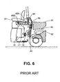
- FIG. 6 of Japanese Utility Model Application Publication No. 58-65123 illustrates the sectional side view of a work vehicle, in which a counter weight 91 provided at the rear side of a work vehicle has a path 92 through which cooling air passes.
- a cooling fan 18 sucks outside air through this path 92. Consequently, an airflow 93 of the outside air passes through a radiator 20, thereby cooling a cooling water running through the radiator 20.
- the airflow 93 which is heated while passing through the radiator 20, is sent to an engine room 17.
- the airflow 93 is sucked by a blower 96 into a duct, and is then passed through an evaporator 94 for freezing cycles provided above the engine room 17.
- the airflow sent in this way is cooled to be cold air 95A and 95B.
- the cold air 95A is blown to the rear part of the operator's seat 14 to prevent the operator's seat 14 from being heated.
- the cold air 95B is returned into the engine room 17 to cool the interior of the engine room 17.
- the conventional technique disclosed in the Japanese Utility Model Application Publication No. 58-65123 has a problem as described below. Specifically, in this conventional technique, the entire airflow sucked from the outside is sent to the radiator 20 where it is heated and then cooled again by the evaporator 94. Thus, this recooling operation requires additional energy, causing an increased amount of energy consumption.
- the airflow heated by the radiator 20 is once sent to the engine room 17, and then sent to the evaporator 94 by a blower 96.
- US-4,304,314 discloses a work vehicle cooling system according to the preamble of claim 1.
- Most of the front space of the cooling fan is covered by the engine, and the engine is placed between the outside air and the cooling fan. Additionally, there exists a distance between the front space of the cooling fan and the outside air. Thus, the flow of cooling air sucked from the outside air by the cooling fan is weak, resulting in a small air curtain effect.
- the cooling fan and the radiator are sequentially arranged along with a cooling airflow from upstream to downstream, the front space of the cooling fan is largely covered by the engine. Thus, the cooling air heated by the engine is sent to the radiator, thereby decreasing the cooling capacity for the radiator.
- DE 1 580 826 A1 discloses an explosive material protected vehicle with battery or combustion engine drive system. It relates to the observation of positive pressure and an airflow serves for generating said positive pressure. It discloses a configuration in which the outside space where the air to be sucked exists, the fan and the seat are sequentially arranged in curve line along with the airflow of the cooling air. The cooling air sucked by the fan flows into the space between the engine and the seat after hitting at a bottom of the vehicle body. This results in a small cooling capacity and a small air curtain effect.
- the present invention is made in view of the above problems. It is an object of the present invention to provide a work vehicle cooling system which has a simple structure and a reduced amount of energy consumption.
- one aspect of the present invention provides a work vehicle cooling system according to claim 1.
- Another aspect of the present invention provides a work vehicle cooling system in which a flow path comprises an air inlet provided between the operator's seat and at least one of the radiator and the oil cooler.
- Still another aspect of the present invention provides a work vehicle cooling system in which the cooling fan is of suction type.
- a cooling fan of discharge type allows the air in the engine room heated by the engine heat to go under the operator's seat
- a cooling fan is of suction type allows the outside air having a low temperature to go under the operator's seat, whereby it is possible for the operator's seat to have a lower temperature.
- a hydraulic excavator 11 includes a travelling section 12, and a swivel 13 rotating in an arbitrary direction mounted on the travelling section 12.
- the swivel 13 has therein an operator's seat 14.
- a working machine 15 having arms 24 and 25 and a bucket 26 attached to the tip end of the arm 25 such that the working machine 15 can swing in an up-and-down direction in a vertical plane.
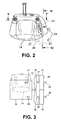
- the operator's seat 14 is provided above an engine room 17 enclosing an engine 16 as shown in Figures 1 and 3 .
- the engine 16 has an output shaft directly connected with a suction-type cooling fan 18 so that the outside air can be sucked into the engine room 17.
- a shroud 19 having a circular opening is provided around the cooling fan 18.
- a radiator 20 for cooling the cooling water and an oil cooler 21 for cooling oil are provided side by side at the upstream side (outer side) of the cooling fan 18.
- the oil cooler 21 has a height lower than the height of the radiator 20.
- an air inlet 22 through which air passes is formed in an upper side of the oil cooler 21.
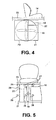
- the airflow 29 is generated.
- a part of the airflow 29 is sent through the radiator 20 and the oil cooler 21 to be sucked into the engine room 17.
- Another part of the airflow 29 is sent through the air inlet 22 to be sucked into the engine room 17.
- Airflow 28 is sent through the radiator 20 and the oil cooler 21, thereby cooling the cooling water passing through the radiator 20 and the operating oil passing through the oil cooler 21. This causes the airflow 28 to be heated to be a hot air having a high temperature.
- a vibration absorption material 23 is provided on the lower side of the operator's seat 14. This vibration absorption material 23 also has a heat insulation effect so that transmission of the heat of the engine 16 to the operator's seat 14 is further prevented.
- the air inlet 22 is provided, which allows the airflow generated by the cooling fan 18 to go between the operator's seat 14 and the engine 16 without passing through the radiator 20 and the oil cooler 21.
- the result is that an air flow path is provided between the operator's seat 14 and the engine 16 through which the airflow 27 having a relatively low temperature passes without passing through the radiator 20 and the oil cooler 21.
- This airflow 27 blocks the heat from the engine 16, thereby preventing the operator's seat 14 from being heated and providing a comfortable operation.
- the embodiment described above is so configured that the operator's seat 14 is located above the engine 16.
- the present invention is not limited to this configuration.
- the operator's seat 14 may be located in front of the engine 16.
- the cooling system may be constructed so that a part of the airflow 27 from the cooling fan 18 passes between the engine 16 and the operator's seat 14 without passing through the oil cooler 21 and the radiator 20.
- the embodiment described above is configured so that the cooling fan 18 is directly connected to the output shaft of the engine 16.
- the cooling fan 18 may be indirectly driven by the engine 16 via a belt, for example.
- the embodiment described above is configured so that the air inlet 22 is provided above the oil cooler 21.
- the present invention is not limited to this configuration.
- the air inlet 22 may be provided between the radiator 20 and the operator's seat 14 by allowing the radiator 20 to have a reduced height.
- the air inlet 22 may be provided above both the radiator 20 and the operator's seat 14.
- the radiator 20 and/or the operator's seat 14 is formed with a notched portion, and the air inlet 22 may be provided in the notched portion.
- the air inlet 22 has a smaller resistance and this allows a larger amount of the air of the airflow 27 passes through the air inlet 22 as compared with that of the airflow 28 passing through the radiator 20 and the oil cooler 21.
- a large amount of air for the airflow 27 passes between the engine 16 and the operator's seat 14 via the air inlet 22 so that the airflow 27 takes a form of an air curtain, which serves to prevent the heat from the engine 16 from being transmitted to the operator's seat 14.
- the operator enjoys a comfortable operation.
- the present invention is not limited to such a configuration.
- the present invention is not limited to a hydraulic excavator and also may be applied to a small construction machine or a forklift.
Landscapes
- Engineering & Computer Science (AREA)
- Physics & Mathematics (AREA)
- Thermal Sciences (AREA)
- Mechanical Engineering (AREA)
- Power Engineering (AREA)
- Cooling, Air Intake And Gas Exhaust, And Fuel Tank Arrangements In Propulsion Units (AREA)
Applications Claiming Priority (2)
| Application Number | Priority Date | Filing Date | Title |
|---|---|---|---|
| JP2002301264A JP2004136722A (ja) | 2002-10-16 | 2002-10-16 | 作業車両用冷却装置 |
| JP2002301264 | 2002-10-16 |
Publications (2)
| Publication Number | Publication Date |
|---|---|
| EP1410930A1 EP1410930A1 (en) | 2004-04-21 |
| EP1410930B1 true EP1410930B1 (en) | 2008-07-16 |
Family
ID=32040798
Family Applications (1)
| Application Number | Title | Priority Date | Filing Date |
|---|---|---|---|
| EP03023271A Expired - Lifetime EP1410930B1 (en) | 2002-10-16 | 2003-10-14 | Work vehicle cooling system |
Country Status (4)
| Country | Link |
|---|---|
| US (1) | US7047912B2 (enExample) |
| EP (1) | EP1410930B1 (enExample) |
| JP (1) | JP2004136722A (enExample) |
| DE (1) | DE60322162D1 (enExample) |
Families Citing this family (4)
| Publication number | Priority date | Publication date | Assignee | Title |
|---|---|---|---|---|
| DE102005035072B4 (de) * | 2005-07-27 | 2020-06-18 | Bayerische Motoren Werke Aktiengesellschaft | Verbrennungskolbenmotor mit einem elektrischen Stellantrieb zur Hubbetätigung der Gaswechselventile |
| JP4996349B2 (ja) * | 2007-05-31 | 2012-08-08 | 株式会社クボタ | 作業車の冷却構造 |
| KR100974278B1 (ko) * | 2008-03-18 | 2010-08-06 | 볼보 컨스트럭션 이키프먼트 홀딩 스웨덴 에이비 | 건설장비의 엔진실 |
| JP5949730B2 (ja) * | 2013-11-07 | 2016-07-13 | コベルコ建機株式会社 | 建設機械の電装品配設構造 |
Family Cites Families (23)
| Publication number | Priority date | Publication date | Assignee | Title |
|---|---|---|---|---|
| DE1580826A1 (de) | 1966-01-27 | 1971-11-11 | Se Fahrzeugwerke Gmbh | Einrichtung an einem explosivstoffgeschuetzten Fahrzeug mit batterieelektrischem oder verbrennungsmotorischem Antrieb |
| GB1259993A (en) | 1969-06-13 | 1972-01-12 | Ch Traktorny Zd | A driver's cab of a vehicle |
| JPS55148607A (en) * | 1979-05-10 | 1980-11-19 | Nissan Motor Co Ltd | Seat cooling device for industrial vehicle |
| JPS5865123A (ja) | 1981-10-13 | 1983-04-18 | タイガー魔法瓶株式会社 | 電子ジヤ− |
| BR8208068A (pt) * | 1982-04-05 | 1984-03-07 | Caterpillar Tractor Co | Construcao de parede para cabina de veiculo |
| US4874036A (en) * | 1987-07-14 | 1989-10-17 | Sanden Corporation | Heating and air conditioning system for a forklift |
| US5143516A (en) * | 1989-02-06 | 1992-09-01 | Paccar Inc. | Recirculation shield and fan shroud assembly |
| JPH08151660A (ja) | 1994-11-30 | 1996-06-11 | Yanmar Diesel Engine Co Ltd | バックホー |
| JPH08240653A (ja) | 1995-03-03 | 1996-09-17 | Hitachi Ltd | 位置情報表示装置 |
| JPH08268088A (ja) * | 1995-03-31 | 1996-10-15 | Hitachi Constr Mach Co Ltd | 建設機械の冷却構造 |
| JP3238310B2 (ja) | 1995-09-29 | 2001-12-10 | 株式会社クボタ | 小型バックホーのボンネット内の配置構造 |
| JP3547239B2 (ja) | 1995-12-08 | 2004-07-28 | 株式会社クボタ | 旋回作業機 |
| JPH09247730A (ja) | 1996-03-05 | 1997-09-19 | Matsushita Electric Ind Co Ltd | 位置検出方法およびその装置 |
| JP3294100B2 (ja) | 1996-03-29 | 2002-06-17 | 株式会社クボタ | バックホウ |
| JPH10104336A (ja) | 1996-09-27 | 1998-04-24 | Mitsui Constr Co Ltd | 移動体管理設備及び、ゴルフ場におけるカート管理設備 |
| JP3159103B2 (ja) | 1997-02-21 | 2001-04-23 | トヨタ自動車株式会社 | 路車間通信システム |
| JPH10312500A (ja) | 1997-05-12 | 1998-11-24 | Mitsubishi Electric Corp | 移動体通信ナビゲーション装置およびその表示制御プログラムを記録した記録媒体 |
| JPH117599A (ja) | 1997-06-17 | 1999-01-12 | Hitachi Ltd | 内蔵型自動車無線システム |
| JPH1181378A (ja) | 1997-09-04 | 1999-03-26 | Kubota Corp | 旋回作業機 |
| JP3681923B2 (ja) * | 1999-06-18 | 2005-08-10 | 株式会社クボタ | 旋回作業機 |
| JP4236229B2 (ja) * | 1999-10-08 | 2009-03-11 | 株式会社小松製作所 | 作業車両の吸音ブレード取付構造 |
| US6431299B1 (en) * | 2000-04-05 | 2002-08-13 | Clark Equipment Company | Cooling air ducting for excavator |
| JP4246360B2 (ja) | 2000-08-24 | 2009-04-02 | 日立建機株式会社 | 旋回式建設機械 |
-
2002
- 2002-10-16 JP JP2002301264A patent/JP2004136722A/ja active Pending
-
2003
- 2003-10-14 DE DE60322162T patent/DE60322162D1/de not_active Expired - Lifetime
- 2003-10-14 US US10/683,281 patent/US7047912B2/en not_active Expired - Fee Related
- 2003-10-14 EP EP03023271A patent/EP1410930B1/en not_active Expired - Lifetime
Also Published As
| Publication number | Publication date |
|---|---|
| US20040074454A1 (en) | 2004-04-22 |
| JP2004136722A (ja) | 2004-05-13 |
| US7047912B2 (en) | 2006-05-23 |
| DE60322162D1 (de) | 2008-08-28 |
| EP1410930A1 (en) | 2004-04-21 |
Similar Documents
| Publication | Publication Date | Title |
|---|---|---|
| CA2779475C (en) | Windrower tractor with parallel heat exchangers for cooling of engine and associated fluids | |
| ES2397986T3 (es) | Trayectorias múltiples de flujos de aire que utilizan un ventilador axial único | |
| EP1031451A2 (en) | Battery cooling duct for a vehicle | |
| JPH08270444A (ja) | 建設機械の冷却構造 | |
| EP1410930B1 (en) | Work vehicle cooling system | |
| US20250189031A1 (en) | Utility vehicle | |
| JP6278694B2 (ja) | 収穫機 | |
| US4175388A (en) | Radiator cooling system | |
| JP6150722B2 (ja) | 収穫機 | |
| JP2002192960A (ja) | 建設機械のエンジンフード | |
| JP4056405B2 (ja) | 草刈機の冷却構造 | |
| JP2566409B2 (ja) | 作業車両の冷却,排風構造 | |
| JP2008296615A (ja) | 建設機械 | |
| JP3208278B2 (ja) | 作業車の原動部冷却装置 | |
| JP2003191758A (ja) | 建設機械の冷却装置 | |
| JPH0525302Y2 (enExample) | ||
| JP6226740B2 (ja) | コンバイン | |
| JPS63270230A (ja) | 車両の冷却、排風構造 | |
| US20240240708A1 (en) | Vehicle | |
| JP7517485B1 (ja) | 作業車両 | |
| JPH0724593Y2 (ja) | 走行式作業機械用ターボ過給機付エンジン | |
| JPH11241366A (ja) | 建設機械の排気装置 | |
| JP2970239B2 (ja) | 農用トラクタのエアコンディショナ装置 | |
| JP2010105463A (ja) | 作業車の原動部構造 | |
| JPH10266262A (ja) | 建設機械の作動油冷却構造 |
Legal Events
| Date | Code | Title | Description |
|---|---|---|---|
| PUAI | Public reference made under article 153(3) epc to a published international application that has entered the european phase |
Free format text: ORIGINAL CODE: 0009012 |
|
| AK | Designated contracting states |
Kind code of ref document: A1 Designated state(s): AT BE BG CH CY CZ DE DK EE ES FI FR GB GR HU IE IT LI LU MC NL PT RO SE SI SK TR |
|
| AX | Request for extension of the european patent |
Extension state: AL LT LV MK |
|
| 17P | Request for examination filed |
Effective date: 20040928 |
|
| AKX | Designation fees paid |
Designated state(s): DE FR GB IT |
|
| 17Q | First examination report despatched |
Effective date: 20061012 |
|
| RAP1 | Party data changed (applicant data changed or rights of an application transferred) |
Owner name: KOMATSU LTD. Owner name: KOMATSU UTILITY CO., LTD. |
|
| GRAP | Despatch of communication of intention to grant a patent |
Free format text: ORIGINAL CODE: EPIDOSNIGR1 |
|
| GRAS | Grant fee paid |
Free format text: ORIGINAL CODE: EPIDOSNIGR3 |
|
| GRAA | (expected) grant |
Free format text: ORIGINAL CODE: 0009210 |
|
| AK | Designated contracting states |
Kind code of ref document: B1 Designated state(s): DE FR GB IT |
|
| REG | Reference to a national code |
Ref country code: GB Ref legal event code: FG4D |
|
| RIN1 | Information on inventor provided before grant (corrected) |
Inventor name: MIMURO, JUNJI, C/O KOMATSU ZENOAH CO. Inventor name: ITOU, SHINICHI, C/O KOMATSU ZENOAH CO. |
|
| REF | Corresponds to: |
Ref document number: 60322162 Country of ref document: DE Date of ref document: 20080828 Kind code of ref document: P |
|
| PLBE | No opposition filed within time limit |
Free format text: ORIGINAL CODE: 0009261 |
|
| STAA | Information on the status of an ep patent application or granted ep patent |
Free format text: STATUS: NO OPPOSITION FILED WITHIN TIME LIMIT |
|
| 26N | No opposition filed |
Effective date: 20090417 |
|
| GBPC | Gb: european patent ceased through non-payment of renewal fee |
Effective date: 20081016 |
|
| REG | Reference to a national code |
Ref country code: FR Ref legal event code: ST Effective date: 20090630 |
|
| PG25 | Lapsed in a contracting state [announced via postgrant information from national office to epo] |
Ref country code: FR Free format text: LAPSE BECAUSE OF NON-PAYMENT OF DUE FEES Effective date: 20081031 |
|
| PG25 | Lapsed in a contracting state [announced via postgrant information from national office to epo] |
Ref country code: GB Free format text: LAPSE BECAUSE OF NON-PAYMENT OF DUE FEES Effective date: 20081016 |
|
| PGFP | Annual fee paid to national office [announced via postgrant information from national office to epo] |
Ref country code: IT Payment date: 20101018 Year of fee payment: 8 |
|
| REG | Reference to a national code |
Ref country code: DE Ref legal event code: R082 Ref document number: 60322162 Country of ref document: DE Representative=s name: BOEHMERT & BOEHMERT, DE |
|
| REG | Reference to a national code |
Ref country code: DE Ref legal event code: R082 Ref document number: 60322162 Country of ref document: DE Representative=s name: BOEHMERT & BOEHMERT ANWALTSPARTNERSCHAFT MBB -, DE Effective date: 20120314 Ref country code: DE Ref legal event code: R081 Ref document number: 60322162 Country of ref document: DE Owner name: KOMATSU LTD., JP Free format text: FORMER OWNER: KOMATSU LTD., KOMATSU UTILITY CO., LTD., , JP Effective date: 20120314 Ref country code: DE Ref legal event code: R081 Ref document number: 60322162 Country of ref document: DE Owner name: KOMATSU LTD., JP Free format text: FORMER OWNERS: KOMATSU LTD., TOKYO, JP; KOMATSU UTILITY CO., LTD., TOKYO, JP Effective date: 20120314 |
|
| PG25 | Lapsed in a contracting state [announced via postgrant information from national office to epo] |
Ref country code: IT Free format text: LAPSE BECAUSE OF NON-PAYMENT OF DUE FEES Effective date: 20121014 |
|
| PGFP | Annual fee paid to national office [announced via postgrant information from national office to epo] |
Ref country code: DE Payment date: 20131009 Year of fee payment: 11 |
|
| REG | Reference to a national code |
Ref country code: DE Ref legal event code: R119 Ref document number: 60322162 Country of ref document: DE |
|
| PG25 | Lapsed in a contracting state [announced via postgrant information from national office to epo] |
Ref country code: DE Free format text: LAPSE BECAUSE OF NON-PAYMENT OF DUE FEES Effective date: 20150501 |