EP1408154A2 - Siebleiste für eine Papiererzeugungsanlage - Google Patents
Siebleiste für eine Papiererzeugungsanlage Download PDFInfo
- Publication number
- EP1408154A2 EP1408154A2 EP03450113A EP03450113A EP1408154A2 EP 1408154 A2 EP1408154 A2 EP 1408154A2 EP 03450113 A EP03450113 A EP 03450113A EP 03450113 A EP03450113 A EP 03450113A EP 1408154 A2 EP1408154 A2 EP 1408154A2
- Authority
- EP
- European Patent Office
- Prior art keywords
- plates
- sieve
- connecting element
- strip
- ceramic material
- Prior art date
- Legal status (The legal status is an assumption and is not a legal conclusion. Google has not performed a legal analysis and makes no representation as to the accuracy of the status listed.)
- Granted
Links
Images




Classifications
-
- D—TEXTILES; PAPER
- D21—PAPER-MAKING; PRODUCTION OF CELLULOSE
- D21F—PAPER-MAKING MACHINES; METHODS OF PRODUCING PAPER THEREON
- D21F1/00—Wet end of machines for making continuous webs of paper
- D21F1/48—Suction apparatus
- D21F1/483—Drainage foils and bars
Definitions
- the subject invention relates to a sifting for a papermaking plant consisting of a support bar and attached to this, to each other subsequent plates of a ceramic material, wherein the Carrying rail and the plates of ceramic material to the adjacent Surfaces are formed with mutually facing recesses, in which fasteners are anchored.
- the subject invention is therefore the object of a To create a sill through which the known prior art Adhesive disadvantages are avoided.
- This is inventively characterized achieved that the connecting elements in the recesses of the plates made of ceramic material are fixed by positive engagement and that side by side located plates by means of at least one over the butt joint extending, common Kauselmentes on the support bar are attached.
- the recesses located in the plates are with undercuts formed, which are engaged behind by the connecting elements are.
- the recesses provided in the plates are by at least one extending in the longitudinal direction of the support bar Groove formed.
- each connecting element is formed by a strip, which in the region assigned to a recess of the plates has a cross-section which is diametrically opposite to the cross-section of the recess.
- the strip-shaped connecting element may be divided in its longitudinal direction into at least two wedge-shaped element pieces.
- each connecting element may be formed as a cone body, which is formed in the area associated with a recess in a plate area with diametrically disposed flats, and it may also be formed with a transverse to the flats slot.
- each connecting element may be formed with a ring-running collar, which comes to rest on the surface of the plate.
- each connecting element on the end face associated with the support bar with an actuating slot or the like.
- the connecting element is designed as a trapezoidal spring body which is elastically deformable in its region assigned to a recess in a plate.
- each connecting element may be formed as a cone-shaped body, which is formed slotted in its part facing the plate and which is provided with an axial bore into which a screw can be screwed, whereby the two parts separated by a slot are radially apart adjustable.
- the connecting element formed by a bracket, which with two semi-annular, through a slot separate bracket parts is formed, wherein in the plates provided grooves have an approximately circular cross-section.
- the grooves of the plates bracket parts Fixed in position by means of a potting compound.
- FIGS. 1 and 1a screening strip for papermaking plants consists of a support strip 1, at the top over the entire length of plates 2 are fixed from ceramic material.
- the support strip 1 is formed over its entire length with a groove 10, by means of which it can be fastened to a support frame and relative to this transversely to the direction of movement of the wire belt of the papermaking plant.
- the support bar 1 is formed with two equally extending over its entire length grooves 11.
- the plates 2 made of ceramic material on its underside with extending over the entire length of grooves 21 are formed.
- the grooves 11 and 21 serve to receive fastening elements 3 for the attachment of the plates 2 made of ceramic material to the support strip. 1
- the connecting elements 3 are arranged so that they extend over the joint between two adjacent plates 2 of ceramic material.
- the support bar 1 and the connecting elements 3 are made of steel, of a hard plastic material, such as polyethylene, glass fiber reinforced plastic, carbon fibers or the like. Materials made. The choice of material for the support strips and the connecting elements is known from the prior art. 2, 2a to 2c, a first type of connecting elements 3 is explained. As can be seen from Fig.2, the grooves 21 provided in the plates 2 are undercut. As can be further seen from Figs.2a to 2c, each connecting element 3 is formed in its upper portion with a broadening, whereby it is adapted to the cross section of the grooves 21 of the plates 2. In order to push the connecting elements 3 in the grooves 21 and to lock in these, they are divided along a vertical plane into two wedge-shaped components 31 and 32.
- the connecting elements 3 are formed with laterally projecting ribs 33.
- the attachment of the connecting elements 3 in the grooves 21 of the plates 2 takes place in that they are inserted into these from their end faces. Since the upper portion of the connecting elements 2 has a groove 21 opposite cross-section, the connecting elements are rigidly fixed in the grooves 21 by positive engagement.
- the attachment of the connecting elements 3 in the grooves 11 of the support strips 1 is effected by introducing a plastic potting compound 4. Due to the positive connection of the plates 2 with the connecting elements 3, this has the desired rigidity. Furthermore, since the connecting elements 3 extend over the butt joints located between two plates 2, the adjacent plates 2 are rigidly fixed to one another, with their abutting edges being at the same height.
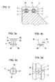
- FIG.3, 3a to 3d is a second embodiment of a connecting element shown.
- This connecting element consists of a conical pin 5, which over part of its height with a Slit 51 and formed with two diametrically opposed flats 52 is. Furthermore, he has a curved head 54 at its tapered end with actuating slots 55.
- This connecting element 5 can due to the flattening 52 in the undercut Grooves 21 of the plates 2 are used. By its rotation by 90 ° whose conical surfaces 53 come to the side walls of the Grooves 21 to the plant and are due to the achieved by the slot 51 Elasticity locked with these form-fitting.
- these connecting elements 5 also become used in the region of the impact in two adjacent plates 2, whereby they are rigidly attached to each other.
- the connecting element 5a shown in FIGS. 4, 4a to 4d differs from the pin 5 according to the 3a to 3d only in that he with a annular collar 57 is formed, which at the bottom of the Plates 2 comes to the plant.
- the connecting element shown in Figures 5, 5a and 5b is also formed by a conical pin 6, which with a central bore 61 and formed with a slot 62, wherein the central bore 61 is assigned a screw 63.
- the screw 63 By screwing in the screw 63 are the two the grooves 21 associated wings of the pin 6 apart moves, whereby it locks in the grooves 21 by positive engagement become.
- the connecting element shown in Figures 6 and 6a consists of a approximately V-shaped spring 7, the two legs 72 to the two side walls the grooves 21 come form-fitting to the plant.
- the connecting element 8 shown in Figures 7 and 7a consists of a keyhole-shaped bracket 8, which with two legs 81 and 82nd is formed, which is inserted into the grooves 11 of the support strip 1 and by means the potting compound 4 are attached. Close to the legs 81 and 82 semi-annular strap parts 83 and 84, which through a slot 85 from each other are separated. Through the slot 85, the bracket 8, the required Elasticity to be inserted into the annular grooves 21 of the plates 2 to become. Since the grooves 21 a corresponding, approximately annular Have cross-section, this is also a positive locking the bracket 8 with the plates 2. Finally, in the grooves 11 and 21 remaining space filled by a plastic mass 4a, thereby the bracket 8 are fixed in position.
- connecting elements extend beyond the butt joint between two plates 2, whereby they are held in their mutual position.
- the connecting elements are inserted into the grooves 21 of the plates 2 and lie against the side walls directly, being held in these by positive engagement.
- the connecting elements in the grooves of the support strips are secured by a potting compound.
- all connecting elements are each arranged in the region of the butt joints between two plates 2 made of ceramic material, whereby by means of the connecting elements in each case two adjacent plates 2 are also rigidly fixed to each other, whereby they are held in the same altitude.
Landscapes
- Paper (AREA)
- Combined Means For Separation Of Solids (AREA)
Abstract
Description
Nach einer weiteren Ausführungsform ist das Verbindungselement als trapezförmiger Federkörper ausgebildet, welcher in seinem einer Ausnehmung in einer Platte zugeordneten Bereich elastisch verformbar ist. Weiters kann jedes Verbindungselement als konusartiger Körper ausgebildet sein, welcher in seinem der Platte zugewandten Teil geschlitzt ausgebildet ist und welcher mit einer axialen Bohrung versehen ist, in welche eine Schraube eindrehbar ist, wodurch die beiden durch einen Schlitz getrennten Teile radial auseinander verstellbar sind.
- Fig.1
- eine erfindungsgemäße Siebleiste, in axonometrischer Darstellung;
- Fig. 1a
- das Detail A der Fig.1, in gegenüber Fig. 1 vergrößertem Maßstab;
- Fig.2
- eine erfindungsgemäße Siebleiste mit einer ersten Ausführungsform eines Verbindungselementes, in vertikalem Schnitt;
- Fig.2a bis 2c
- das Verbindungselement gemäß Fig.2, in Vorderansicht, in Draufsicht und in axonometrischer Darstellung;
- Fig.3
- eine erfindungsgemäße Siebleiste mit einer zweiten Ausführungsform eines Verbindungselementes, in vertikalem Schnitt;
- Fig.3a bis 3d
- das Verbindungselement gemäß Fig.3, in zwei Seitenansichten und in zwei Draufsichten;
- Fig.4
- eine erfindungsgemäße Siebleiste mit einer dritten Ausführungsform eines Verbindungselementes, in vertikalem Schnitt;
- Fig.4a bis 4d
- das Verbindungselement gemäß Fig.4, in zwei Seitenansichten und in zwei Draufsichten;
- Fig.5
- eine erfindungsgemäße Siebleiste mit einer vierten Ausführungsform eines Verbindungselementes, in vertikalem Schnitt;
- Fig.5a und 5b
- das Verbindungselement gemäß Fig.5, in zwei Stadien von dessen Verwendung;
- Fig.6
- eine erfindungsgemäße Siebleiste mit einer fünften Ausführungsform eines Verbindungselementes, in vertikalem Schnitt;
- Fig.6a
- das Verbindungselement gemäß Fig.6, in Stirnansicht;
- Fig.7
- eine erfindungsgemäße Siebleiste in einer sechsten Ausführungsform; und
- Fig.7a
- das Verbindungselement gemäß Fig.7, in Stirnansicht.
Die Verbindungselemente 3 sind so angeordnet, daß sie sich über den Stoß zwischen zwei nebeneinander befindlichen Platten 2 aus keramischem Material erstrecken.
Anhand der Fig.2, 2a bis 2c ist eine erste Art von Verbindungselementen 3 erläutert. Wie dies aus Fig.2 ersichtlich ist, sind die in den Platten 2 vorgesehenen Nuten 21 hinterschnitten ausgebildet. Wie dies weiters aus den Fig.2a bis 2c ersichtlich ist, ist jedes Verbindungselement 3 in seinem oberen Bereich mit einer Verbreiterung ausgebildet, wodurch es dem Querschnitt der Nuten 21 der Platten 2 angepaßt ist. Um die Verbindungselemente 3 in die Nuten 21 einschieben und in diesen verriegeln zu können, sind sie längs einer vertikalen Ebene in zwei keilförmige Bauteile 31 und 32 unterteilt. An ihrer Unterseite sind die Verbindungselemente 3 mit seitlich abragenden Rippen 33 ausgebildet. Die Befestigung der Verbindungselemente 3 in den Nuten 21 der Platten 2 erfolgt dadurch, daß sie in diese von deren Stirnflächen her eingeschoben werden. Da der obere Bereich der Verbindungselemente 2 einen den Nuten 21 gegengleichen Querschnitt aufweist, werden die Verbindungselemente in den Nuten 21 durch Formschluß starr befestigt. Die Befestigung der Verbindungselemente 3 in den Nuten 11 der Tragleisten 1 erfolgt durch Einbringen einer aus Kunststoff bestehenden Vergußmasse 4. Aufgrund der formschlüssigen Verbindung der Platten 2 mit den Verbindungselementen 3 weist diese die angestrebte Starrheit auf. Da sich weiters die Verbindungselemente 3 über die zwischen zwei Platten 2 befindlichen Stoßfugen erstrecken, sind auch die nebeneinander befindlichen Platten 2 aneinander starr befestigt, wobei sich deren Stoßkanten auf der gleichen Höhe befinden.
Bei sämtlichen Ausführungsbeispielen sind die Verbindungselemente in die Nuten 21 der Platten 2 eingesetzt und liegen an deren Seitenwände unmittelbar an, wobei sie in diesen durch Formschluß gehalten sind. Die Verbindungselemente in den Nuten der Tragleisten sind durch eine Vergußmasse befestigt. Weiters sind sämtliche Verbindungselemente jeweils im Bereich der Stoßfugen zwischen zwei Platten 2 aus keramischem Material angeordnet, wodurch mittels der Verbindungselemente jeweils zwei nebeneinander befindliche Platten 2 auch miteinander starr befestigt sind, wodurch sie in der gleichen Höhenlage gehalten sind.
Claims (13)
- Siebleiste für eine Papiererzeugungsanlage bestehend aus einer Tragleiste (1) und an dieser befestigten, aneinander anschließenden Platten (2) aus einem keramischen Material, wobei die Tragleiste (1) und die Platten (2) aus keramischem Material an den aneinander liegenden Flächen mit einander zugewandten Ausnehmungen (11, 21) ausgebildet sind, in welchen Verbindungselemente (3) verankert sind, dadurch gekennzeichnet, daß diese Verbindungselemente (3) in den Ausnehmungen der Platten (2) aus keramischem Material durch Formschluß befestigt sind und daß nebeneinander befindliche Platten (2) mittels mindestens eines sich über die Stoßfuge erstreckenden, gemeinsamen Verbindungselementes (3) an der Tragleiste (1) befestigt sind.
- Siebleiste nach Patentanspruch 1, dadurch gekennzeichnet, daß die in den Platten (2) befindlichen Ausnehmungen (21) mit Hinterschneidungen ausgebildet sind, welche von den Verbindungselementen (3) hintergriffen sind.
- Siebleiste nach einem der Patentansprüche 1 und 2, dadurch gekennzeichnet, daß die in den Platten (2) vorgesehenen Ausnehmungen durch mindestens eine sich in Längsrichtung der Tragleiste (1) erstreckende Nut (21) gebildet sind.
- Siebleiste nach einem der Patentansprüche 1 bis 3, dadurch gekennzeichnet, daß ein Verbindungselement (3) durch eine Leiste gebildet ist, welche in dem einer Ausnehmung (21) der Platten (2) zugeordneten Bereich eine dem Querschnitt der Ausnehmung (21) gegengleichen Querschnitt aufweist.
- Siebleiste nach Patentanspruch 4, dadurch gekennzeichnet, daß das leistenförmige Verbindungselement (3) in dessen Längsrichtung in mindestens zwei keilförmige Elementestücke (31, 32) unterteilt ist.
- Siebleiste nach einem der Patentansprüche 1 bis 3, dadurch gekennzeichnet, daß ein Verbindungselement als Konuskörper (5) ausgebildet ist, welcher in dem einer Ausnehmung (21) in einer Platte (2) zugeordneten Bereich mit diametral angeordneten Abflachungen (52) ausgebildet ist.
- Siebleiste nach Patentanspruch 6, dadurch gekennzeichnet, daß das Verbindungselement mit einem quer zu den Abflachungen (52) verlaufenden Schlitz (51) ausgebildet ist.
- Siebleiste nach einem der Patentansprüche 6 und 7, dadurch gekennzeichnet, daß das Verbindungselement (5a) mit einem ringsumlaufenden Bund (57) ausgebildet ist, welcher an die Oberfläche der Platte (2) zur Anlage kommt.
- Siebleiste nach einem der Patentansprüche 6 bis 8, dadurch gekennzeichnet, daß das Verbindungselement (5) an der der Tragleiste (1) zugeordneten Stirnfläche mit einem Betätigungsschlitz (55) od.dgl. ausgebildet ist.
- Siebleiste nach einem der Patentansprüche 1 bis 3, dadurch gekennzeichnet, daß ein Verrbindungselement als trapezförmiger Federkörper (7) ausgebildet ist, welcher in seinem einer Ausnehmung (21) in einer Platte (2) zugeordneten Bereich elastisch verformbar ist.
- Siebleiste nach einem der Patentansprüche 1 bis 3, dadurch gekennzeichnet, daß ein Verbindungselement als konusartiger Körper (6) ausgebildet ist, welcher in seinem der Platte (2) zugewandten Teil geschlitzt ausgebildet ist und welcher mit einer axialen Bohrung (61) versehen ist, in welche eine Schraube (63) eindrehbar ist, wodurch die beiden durch einen Schlitz (62) getrennten Teile radial auseinander verstellbar sind.
- Siebleiste nach einem der Patentansprüche 1 bis 3, dadurch gekennzeichnet, daß ein Verbindungselement durch einen Bügel (8) gebildet ist, welcher mit zwei halbringförmigen, durch einen Schlitz (85) getrennten Bügelteilen (83, 84) ausgebildet ist und daß die in den Platten (2) vorgesehenen Nuten (21) einen angenähert kreisförmigen Querschnitt aufweisen.
- Siebleiste nach Patentanspruch 12, dadurch gekennzeichnet, daß die in den Nuten (21) der Platten (2) befindlichen Bügelteile (83, 84) mittels einer Vergußmasse (4a) lagefixiert sind.
Priority Applications (1)
| Application Number | Priority Date | Filing Date | Title |
|---|---|---|---|
| AT03450113T ATE330062T1 (de) | 2002-09-12 | 2003-05-08 | Siebleiste für eine papiererzeugungsanlage |
Applications Claiming Priority (4)
| Application Number | Priority Date | Filing Date | Title |
|---|---|---|---|
| AT13632002 | 2002-09-12 | ||
| AT13632002A AT412217B (de) | 2002-09-12 | 2002-09-12 | Siebleiste für eine papiererzeugungsanlage |
| AT16142002 | 2002-10-24 | ||
| AT0161402A AT411770B (de) | 2002-09-12 | 2002-10-24 | Siebleiste für eine papiererzeugungsanlage |
Publications (3)
| Publication Number | Publication Date |
|---|---|
| EP1408154A2 true EP1408154A2 (de) | 2004-04-14 |
| EP1408154A3 EP1408154A3 (de) | 2004-07-07 |
| EP1408154B1 EP1408154B1 (de) | 2006-06-14 |
Family
ID=28792683
Family Applications (1)
| Application Number | Title | Priority Date | Filing Date |
|---|---|---|---|
| EP03450113A Expired - Lifetime EP1408154B1 (de) | 2002-09-12 | 2003-05-08 | Siebleiste für eine Papiererzeugungsanlage |
Country Status (9)
| Country | Link |
|---|---|
| US (1) | US7169264B2 (de) |
| EP (1) | EP1408154B1 (de) |
| JP (1) | JP4493948B2 (de) |
| CN (1) | CN1247854C (de) |
| AT (1) | AT411770B (de) |
| BR (1) | BR0302414B1 (de) |
| CA (1) | CA2435706C (de) |
| DE (1) | DE50303800D1 (de) |
| ES (1) | ES2261910T3 (de) |
Families Citing this family (9)
| Publication number | Priority date | Publication date | Assignee | Title |
|---|---|---|---|---|
| AT500283B8 (de) * | 2004-03-17 | 2007-02-15 | Bartelmuss Klaus Ing | Siebleiste für papiererzeugungsanlagen |
| AT503435B1 (de) * | 2006-07-20 | 2007-10-15 | Bartelmuss Klaus Ing | Siebleiste für papiererzeugungsanlagen |
| WO2008147766A1 (en) * | 2007-05-23 | 2008-12-04 | Astenjohnson, Inc. | Papermaking machine dewatering blade incorporating attachment mechanism |
| FI119648B (fi) * | 2007-06-12 | 2009-01-30 | Metso Paper Inc | Vedenpoistoelin rainanmuodostuskoneelle, menetelmä rainanmuodostuskoneella käytettävän vedenpoistoelimen muodostamiseksi ja pintaosa vedenpoistoelimeen rainanmuodostuskoneelle |
| CN102277770B (zh) * | 2007-11-19 | 2014-10-15 | 维美德技术有限公司 | 传送吸箱 |
| DE102008040032A1 (de) * | 2008-06-30 | 2009-12-31 | Voith Patent Gmbh | Leistenanordnung für eine Maschine zur Herstellung einer Faserstoffbahn |
| ATE550480T1 (de) * | 2008-12-18 | 2012-04-15 | Klaus Bartelmuss | Einrichtung zur lösbaren befestigung einer siebleiste in einer anlage zur erzeugung von papier |
| FI121796B (fi) | 2009-12-09 | 2011-04-15 | Metso Paper Inc | Staattinen elementti kuiturainakonetta varten |
| KR102333079B1 (ko) | 2019-12-09 | 2021-12-01 | 삼성전기주식회사 | 코일 부품 |
Family Cites Families (13)
| Publication number | Priority date | Publication date | Assignee | Title |
|---|---|---|---|---|
| AT295313B (de) * | 1967-12-22 | 1971-12-27 | Leder & Riemen Patent | Mit dem Sieb oder Filz einer Papier- oder Zellstoffentwässerungsmaschine in gleitender Berührung stehender Bauteil |
| DE2229506A1 (de) * | 1971-06-17 | 1972-12-21 | Bartelmuss, Heinrich, Ing , Teufen bach, Steiermark (Osterreich) | Maschinenteile, insbesondere Belag teile und Verfahren zu deren Herstellung |
| US3870597A (en) * | 1972-05-24 | 1975-03-11 | Beloit Corp | Drainage foil having a foil blade insert |
| US3928125A (en) * | 1972-12-18 | 1975-12-23 | Feldmuehle Anlagen Prod | Water extraction apparatus for papermaking machine |
| AT348850B (de) * | 1973-07-02 | 1979-03-12 | Sotec Ag | Mit dem sieb oder filz einer stoffentwaessern- den maschine in gleitender beruehrung stehendes entwaesserungselement |
| US4449565A (en) * | 1979-06-13 | 1984-05-22 | Heinrich Bartelmuss | Connecting arrangement for support members cooperating with a liquid permeable web |
| US4280869A (en) * | 1980-02-14 | 1981-07-28 | Albany International Corp. | Suction dewatering system with cam actuated adjustable slot |
| JPS599038Y2 (ja) * | 1981-03-25 | 1984-03-21 | 日立化成工業株式会社 | 抄紙機用脱水ブレ−ド |
| JPS6255597U (de) * | 1985-09-27 | 1987-04-06 | ||
| JPH0345999Y2 (de) * | 1986-12-29 | 1991-09-27 | ||
| DE3823882A1 (de) * | 1988-07-14 | 1990-01-18 | Feldmuehle Ag | Schlitzsauger |
| US5630910A (en) * | 1995-06-26 | 1997-05-20 | Jwi Ltd. | Clip fastener for a dewatering box |
| US20040011493A1 (en) * | 2002-06-21 | 2004-01-22 | Coorstek, Inc. | Apparatus having wear-resistant surface and method for making |
-
2002
- 2002-10-24 AT AT0161402A patent/AT411770B/de not_active IP Right Cessation
-
2003
- 2003-05-08 ES ES03450113T patent/ES2261910T3/es not_active Expired - Lifetime
- 2003-05-08 DE DE50303800T patent/DE50303800D1/de not_active Expired - Lifetime
- 2003-05-08 EP EP03450113A patent/EP1408154B1/de not_active Expired - Lifetime
- 2003-07-01 US US10/611,083 patent/US7169264B2/en not_active Expired - Lifetime
- 2003-07-14 BR BRPI0302414-8A patent/BR0302414B1/pt active IP Right Grant
- 2003-07-15 JP JP2003274686A patent/JP4493948B2/ja not_active Expired - Fee Related
- 2003-07-21 CN CNB031501605A patent/CN1247854C/zh not_active Expired - Fee Related
- 2003-07-22 CA CA002435706A patent/CA2435706C/en not_active Expired - Lifetime
Also Published As
| Publication number | Publication date |
|---|---|
| ATA16142002A (de) | 2003-10-15 |
| CA2435706C (en) | 2008-04-29 |
| JP2004100134A (ja) | 2004-04-02 |
| US20040050521A1 (en) | 2004-03-18 |
| JP4493948B2 (ja) | 2010-06-30 |
| CN1487143A (zh) | 2004-04-07 |
| CA2435706A1 (en) | 2004-03-12 |
| EP1408154A3 (de) | 2004-07-07 |
| EP1408154B1 (de) | 2006-06-14 |
| BR0302414B1 (pt) | 2013-02-19 |
| DE50303800D1 (de) | 2006-07-27 |
| BR0302414A (pt) | 2004-09-08 |
| US7169264B2 (en) | 2007-01-30 |
| ES2261910T3 (es) | 2006-11-16 |
| AT411770B (de) | 2004-05-25 |
| CN1247854C (zh) | 2006-03-29 |
Similar Documents
| Publication | Publication Date | Title |
|---|---|---|
| AT505453B1 (de) | Abdeckvorrichtung für fussbodenbeläge | |
| EP0421056B1 (de) | Halteelement aus Kunststoff | |
| EP0483636B1 (de) | Halteelement aus Kunststoff | |
| DE3827259A1 (de) | Siebanordnung | |
| DE3307916A1 (de) | Siebbelag mit auswechselbaren siebelementen | |
| DE2924571A1 (de) | Siebelement und dieses enthaltende vorrichtung | |
| EP1408154B1 (de) | Siebleiste für eine Papiererzeugungsanlage | |
| DE4403131A1 (de) | Ankerbolzen zur Verankerung mittels einer Verbundmasse und Verfahren zu dessen Herstellung | |
| AT524317B1 (de) | Abstreifleiste und Bausatz zur Verwendung in einer Anlage zur Erzeugung einer Papierbahn | |
| EP1916331B1 (de) | Siebleiste für Papiererzeugungsanlagen | |
| DE19528205C2 (de) | Zweiteiliger Stollen | |
| DE102009042357B3 (de) | Spaltsieb und Haltelehre für dessen Herstellung | |
| EP3690268A2 (de) | Wälzkörperkäfig für wälzlager | |
| AT503435B1 (de) | Siebleiste für papiererzeugungsanlagen | |
| DE4300303A1 (de) | Spannsieb | |
| AT412217B (de) | Siebleiste für eine papiererzeugungsanlage | |
| EP0350827A2 (de) | Schlitzsauger | |
| AT500283A1 (de) | Siebleiste für papiererzeugungsanlagen | |
| CH696399A5 (de) | Deckelstab für eine Karde, der einen Tragkörper und einen lösbaren Garniturteil aufweist. | |
| DE102007055479B4 (de) | Knotenelement für eine Fachwerkskonstruktion | |
| DD141627A1 (de) | Einrichtung zur befestigung und verspannung von kunststoffsiebboeden | |
| EP3241618A1 (de) | Siebrost | |
| DE202006011973U1 (de) | Längsträger | |
| DE3942591A1 (de) | Siebkorb | |
| DE10065931A1 (de) | Verfahren zur Herstellung von bei der Nasssiebung von Papierfasersuspensionen verwendbaren Sieben |
Legal Events
| Date | Code | Title | Description |
|---|---|---|---|
| PUAI | Public reference made under article 153(3) epc to a published international application that has entered the european phase |
Free format text: ORIGINAL CODE: 0009012 |
|
| AK | Designated contracting states |
Kind code of ref document: A2 Designated state(s): AT BE BG CH CY CZ DE DK EE ES FI FR GB GR HU IE IT LI LU MC NL PT RO SE SI SK TR |
|
| AX | Request for extension of the european patent |
Extension state: AL LT LV MK |
|
| PUAL | Search report despatched |
Free format text: ORIGINAL CODE: 0009013 |
|
| AK | Designated contracting states |
Kind code of ref document: A3 Designated state(s): AT BE BG CH CY CZ DE DK EE ES FI FR GB GR HU IE IT LI LU MC NL PT RO SE SI SK TR |
|
| AX | Request for extension of the european patent |
Extension state: AL LT LV MK |
|
| 17P | Request for examination filed |
Effective date: 20040826 |
|
| AKX | Designation fees paid |
Designated state(s): AT BE BG CH CY CZ DE DK EE ES FI FR GB GR HU IE IT LI LU MC NL PT RO SE SI SK TR |
|
| GRAP | Despatch of communication of intention to grant a patent |
Free format text: ORIGINAL CODE: EPIDOSNIGR1 |
|
| GRAS | Grant fee paid |
Free format text: ORIGINAL CODE: EPIDOSNIGR3 |
|
| GRAA | (expected) grant |
Free format text: ORIGINAL CODE: 0009210 |
|
| AK | Designated contracting states |
Kind code of ref document: B1 Designated state(s): AT BE BG CH CY CZ DE DK EE ES FI FR GB GR HU IE IT LI LU MC NL PT RO SE SI SK TR |
|
| PG25 | Lapsed in a contracting state [announced via postgrant information from national office to epo] |
Ref country code: SI Free format text: LAPSE BECAUSE OF FAILURE TO SUBMIT A TRANSLATION OF THE DESCRIPTION OR TO PAY THE FEE WITHIN THE PRESCRIBED TIME-LIMIT Effective date: 20060614 Ref country code: NL Free format text: LAPSE BECAUSE OF FAILURE TO SUBMIT A TRANSLATION OF THE DESCRIPTION OR TO PAY THE FEE WITHIN THE PRESCRIBED TIME-LIMIT Effective date: 20060614 Ref country code: IT Free format text: LAPSE BECAUSE OF FAILURE TO SUBMIT A TRANSLATION OF THE DESCRIPTION OR TO PAY THE FEE WITHIN THE PRESCRIBED TIME-LIMIT;WARNING: LAPSES OF ITALIAN PATENTS WITH EFFECTIVE DATE BEFORE 2007 MAY HAVE OCCURRED AT ANY TIME BEFORE 2007. THE CORRECT EFFECTIVE DATE MAY BE DIFFERENT FROM THE ONE RECORDED. Effective date: 20060614 Ref country code: SK Free format text: LAPSE BECAUSE OF FAILURE TO SUBMIT A TRANSLATION OF THE DESCRIPTION OR TO PAY THE FEE WITHIN THE PRESCRIBED TIME-LIMIT Effective date: 20060614 Ref country code: IE Free format text: LAPSE BECAUSE OF FAILURE TO SUBMIT A TRANSLATION OF THE DESCRIPTION OR TO PAY THE FEE WITHIN THE PRESCRIBED TIME-LIMIT Effective date: 20060614 Ref country code: CZ Free format text: LAPSE BECAUSE OF FAILURE TO SUBMIT A TRANSLATION OF THE DESCRIPTION OR TO PAY THE FEE WITHIN THE PRESCRIBED TIME-LIMIT Effective date: 20060614 Ref country code: RO Free format text: LAPSE BECAUSE OF FAILURE TO SUBMIT A TRANSLATION OF THE DESCRIPTION OR TO PAY THE FEE WITHIN THE PRESCRIBED TIME-LIMIT Effective date: 20060614 |
|
| REG | Reference to a national code |
Ref country code: GB Ref legal event code: FG4D Free format text: NOT ENGLISH |
|
| REG | Reference to a national code |
Ref country code: CH Ref legal event code: EP |
|
| REG | Reference to a national code |
Ref country code: SE Ref legal event code: TRGR |
|
| REG | Reference to a national code |
Ref country code: CH Ref legal event code: NV Representative=s name: LUCHS & PARTNER PATENTANWAELTE |
|
| GBT | Gb: translation of ep patent filed (gb section 77(6)(a)/1977) |
Effective date: 20060614 |
|
| REG | Reference to a national code |
Ref country code: IE Ref legal event code: FG4D Free format text: LANGUAGE OF EP DOCUMENT: GERMAN |
|
| REF | Corresponds to: |
Ref document number: 50303800 Country of ref document: DE Date of ref document: 20060727 Kind code of ref document: P |
|
| PG25 | Lapsed in a contracting state [announced via postgrant information from national office to epo] |
Ref country code: DK Free format text: LAPSE BECAUSE OF FAILURE TO SUBMIT A TRANSLATION OF THE DESCRIPTION OR TO PAY THE FEE WITHIN THE PRESCRIBED TIME-LIMIT Effective date: 20060914 |
|
| PG25 | Lapsed in a contracting state [announced via postgrant information from national office to epo] |
Ref country code: PT Free format text: LAPSE BECAUSE OF FAILURE TO SUBMIT A TRANSLATION OF THE DESCRIPTION OR TO PAY THE FEE WITHIN THE PRESCRIBED TIME-LIMIT Effective date: 20061114 |
|
| REG | Reference to a national code |
Ref country code: ES Ref legal event code: FG2A Ref document number: 2261910 Country of ref document: ES Kind code of ref document: T3 |
|
| ET | Fr: translation filed | ||
| NLV1 | Nl: lapsed or annulled due to failure to fulfill the requirements of art. 29p and 29m of the patents act | ||
| REG | Reference to a national code |
Ref country code: IE Ref legal event code: FD4D |
|
| PLBE | No opposition filed within time limit |
Free format text: ORIGINAL CODE: 0009261 |
|
| STAA | Information on the status of an ep patent application or granted ep patent |
Free format text: STATUS: NO OPPOSITION FILED WITHIN TIME LIMIT |
|
| 26N | No opposition filed |
Effective date: 20070315 |
|
| BERE | Be: lapsed |
Owner name: BARTELMUSS, KLAUS Effective date: 20070531 |
|
| PG25 | Lapsed in a contracting state [announced via postgrant information from national office to epo] |
Ref country code: MC Free format text: LAPSE BECAUSE OF NON-PAYMENT OF DUE FEES Effective date: 20070531 |
|
| PG25 | Lapsed in a contracting state [announced via postgrant information from national office to epo] |
Ref country code: BE Free format text: LAPSE BECAUSE OF NON-PAYMENT OF DUE FEES Effective date: 20070531 |
|
| PG25 | Lapsed in a contracting state [announced via postgrant information from national office to epo] |
Ref country code: GR Free format text: LAPSE BECAUSE OF FAILURE TO SUBMIT A TRANSLATION OF THE DESCRIPTION OR TO PAY THE FEE WITHIN THE PRESCRIBED TIME-LIMIT Effective date: 20060915 |
|
| PG25 | Lapsed in a contracting state [announced via postgrant information from national office to epo] |
Ref country code: BG Free format text: LAPSE BECAUSE OF FAILURE TO SUBMIT A TRANSLATION OF THE DESCRIPTION OR TO PAY THE FEE WITHIN THE PRESCRIBED TIME-LIMIT Effective date: 20060914 |
|
| PG25 | Lapsed in a contracting state [announced via postgrant information from national office to epo] |
Ref country code: EE Free format text: LAPSE BECAUSE OF FAILURE TO SUBMIT A TRANSLATION OF THE DESCRIPTION OR TO PAY THE FEE WITHIN THE PRESCRIBED TIME-LIMIT Effective date: 20060614 |
|
| PG25 | Lapsed in a contracting state [announced via postgrant information from national office to epo] |
Ref country code: LU Free format text: LAPSE BECAUSE OF NON-PAYMENT OF DUE FEES Effective date: 20070508 Ref country code: CY Free format text: LAPSE BECAUSE OF FAILURE TO SUBMIT A TRANSLATION OF THE DESCRIPTION OR TO PAY THE FEE WITHIN THE PRESCRIBED TIME-LIMIT Effective date: 20060614 |
|
| PG25 | Lapsed in a contracting state [announced via postgrant information from national office to epo] |
Ref country code: HU Free format text: LAPSE BECAUSE OF FAILURE TO SUBMIT A TRANSLATION OF THE DESCRIPTION OR TO PAY THE FEE WITHIN THE PRESCRIBED TIME-LIMIT Effective date: 20061215 Ref country code: TR Free format text: LAPSE BECAUSE OF FAILURE TO SUBMIT A TRANSLATION OF THE DESCRIPTION OR TO PAY THE FEE WITHIN THE PRESCRIBED TIME-LIMIT Effective date: 20060614 |
|
| REG | Reference to a national code |
Ref country code: FR Ref legal event code: PLFP Year of fee payment: 14 |
|
| REG | Reference to a national code |
Ref country code: FR Ref legal event code: PLFP Year of fee payment: 15 |
|
| REG | Reference to a national code |
Ref country code: FR Ref legal event code: PLFP Year of fee payment: 16 |
|
| PGFP | Annual fee paid to national office [announced via postgrant information from national office to epo] |
Ref country code: DE Payment date: 20210520 Year of fee payment: 19 Ref country code: FR Payment date: 20210520 Year of fee payment: 19 Ref country code: FI Payment date: 20210520 Year of fee payment: 19 Ref country code: IT Payment date: 20210527 Year of fee payment: 19 |
|
| PGFP | Annual fee paid to national office [announced via postgrant information from national office to epo] |
Ref country code: GB Payment date: 20210520 Year of fee payment: 19 Ref country code: CH Payment date: 20210519 Year of fee payment: 19 Ref country code: SE Payment date: 20210519 Year of fee payment: 19 Ref country code: AT Payment date: 20210527 Year of fee payment: 19 |
|
| PGFP | Annual fee paid to national office [announced via postgrant information from national office to epo] |
Ref country code: ES Payment date: 20210721 Year of fee payment: 19 |
|
| REG | Reference to a national code |
Ref country code: DE Ref legal event code: R119 Ref document number: 50303800 Country of ref document: DE |
|
| REG | Reference to a national code |
Ref country code: CH Ref legal event code: PL |
|
| REG | Reference to a national code |
Ref country code: SE Ref legal event code: EUG |
|
| REG | Reference to a national code |
Ref country code: AT Ref legal event code: MM01 Ref document number: 330062 Country of ref document: AT Kind code of ref document: T Effective date: 20220508 |
|
| GBPC | Gb: european patent ceased through non-payment of renewal fee |
Effective date: 20220508 |
|
| PG25 | Lapsed in a contracting state [announced via postgrant information from national office to epo] |
Ref country code: SE Free format text: LAPSE BECAUSE OF NON-PAYMENT OF DUE FEES Effective date: 20220509 Ref country code: LI Free format text: LAPSE BECAUSE OF NON-PAYMENT OF DUE FEES Effective date: 20220531 Ref country code: FI Free format text: LAPSE BECAUSE OF NON-PAYMENT OF DUE FEES Effective date: 20220508 Ref country code: CH Free format text: LAPSE BECAUSE OF NON-PAYMENT OF DUE FEES Effective date: 20220531 Ref country code: AT Free format text: LAPSE BECAUSE OF NON-PAYMENT OF DUE FEES Effective date: 20220508 |
|
| PG25 | Lapsed in a contracting state [announced via postgrant information from national office to epo] |
Ref country code: FR Free format text: LAPSE BECAUSE OF NON-PAYMENT OF DUE FEES Effective date: 20220531 |
|
| PG25 | Lapsed in a contracting state [announced via postgrant information from national office to epo] |
Ref country code: GB Free format text: LAPSE BECAUSE OF NON-PAYMENT OF DUE FEES Effective date: 20220508 Ref country code: DE Free format text: LAPSE BECAUSE OF NON-PAYMENT OF DUE FEES Effective date: 20221201 |
|
| REG | Reference to a national code |
Ref country code: ES Ref legal event code: FD2A Effective date: 20230627 |
|
| PG25 | Lapsed in a contracting state [announced via postgrant information from national office to epo] |
Ref country code: IT Free format text: LAPSE BECAUSE OF NON-PAYMENT OF DUE FEES Effective date: 20220508 Ref country code: ES Free format text: LAPSE BECAUSE OF NON-PAYMENT OF DUE FEES Effective date: 20220509 |