EP1406451B1 - Verfahren zur Codierung und Decodierung von H.264 Bildern mittels eines virtuellen Anzeigepuffers. - Google Patents
Verfahren zur Codierung und Decodierung von H.264 Bildern mittels eines virtuellen Anzeigepuffers. Download PDFInfo
- Publication number
- EP1406451B1 EP1406451B1 EP20030741225 EP03741225A EP1406451B1 EP 1406451 B1 EP1406451 B1 EP 1406451B1 EP 20030741225 EP20030741225 EP 20030741225 EP 03741225 A EP03741225 A EP 03741225A EP 1406451 B1 EP1406451 B1 EP 1406451B1
- Authority
- EP
- European Patent Office
- Prior art keywords
- picture
- decoded
- pictures
- memory
- display
- Prior art date
- Legal status (The legal status is an assumption and is not a legal conclusion. Google has not performed a legal analysis and makes no representation as to the accuracy of the status listed.)
- Expired - Lifetime
Links
Images


Classifications
-
- H—ELECTRICITY
- H04—ELECTRIC COMMUNICATION TECHNIQUE
- H04N—PICTORIAL COMMUNICATION, e.g. TELEVISION
- H04N21/00—Selective content distribution, e.g. interactive television or video on demand [VOD]
- H04N21/40—Client devices specifically adapted for the reception of or interaction with content, e.g. set-top-box [STB]; Operations thereof
- H04N21/43—Processing of content or additional data, e.g. demultiplexing additional data from a digital video stream; Elementary client operations, e.g. monitoring of home network or synchronising decoder's clock; Client middleware
- H04N21/44—Processing of video elementary streams, e.g. splicing a video clip retrieved from local storage with an incoming video stream, rendering scenes according to MPEG-4 scene graphs
- H04N21/44004—Processing of video elementary streams, e.g. splicing a video clip retrieved from local storage with an incoming video stream, rendering scenes according to MPEG-4 scene graphs involving video buffer management, e.g. video decoder buffer or video display buffer
-
- G—PHYSICS
- G06—COMPUTING; CALCULATING OR COUNTING
- G06T—IMAGE DATA PROCESSING OR GENERATION, IN GENERAL
- G06T7/00—Image analysis
- G06T7/20—Analysis of motion
-
- G—PHYSICS
- G06—COMPUTING; CALCULATING OR COUNTING
- G06T—IMAGE DATA PROCESSING OR GENERATION, IN GENERAL
- G06T1/00—General purpose image data processing
- G06T1/60—Memory management
-
- G—PHYSICS
- G09—EDUCATION; CRYPTOGRAPHY; DISPLAY; ADVERTISING; SEALS
- G09G—ARRANGEMENTS OR CIRCUITS FOR CONTROL OF INDICATING DEVICES USING STATIC MEANS TO PRESENT VARIABLE INFORMATION
- G09G5/00—Control arrangements or circuits for visual indicators common to cathode-ray tube indicators and other visual indicators
- G09G5/18—Timing circuits for raster scan displays
-
- H—ELECTRICITY
- H04—ELECTRIC COMMUNICATION TECHNIQUE
- H04N—PICTORIAL COMMUNICATION, e.g. TELEVISION
- H04N19/00—Methods or arrangements for coding, decoding, compressing or decompressing digital video signals
- H04N19/10—Methods or arrangements for coding, decoding, compressing or decompressing digital video signals using adaptive coding
- H04N19/102—Methods or arrangements for coding, decoding, compressing or decompressing digital video signals using adaptive coding characterised by the element, parameter or selection affected or controlled by the adaptive coding
- H04N19/103—Selection of coding mode or of prediction mode
- H04N19/105—Selection of the reference unit for prediction within a chosen coding or prediction mode, e.g. adaptive choice of position and number of pixels used for prediction
-
- H—ELECTRICITY
- H04—ELECTRIC COMMUNICATION TECHNIQUE
- H04N—PICTORIAL COMMUNICATION, e.g. TELEVISION
- H04N19/00—Methods or arrangements for coding, decoding, compressing or decompressing digital video signals
- H04N19/10—Methods or arrangements for coding, decoding, compressing or decompressing digital video signals using adaptive coding
- H04N19/102—Methods or arrangements for coding, decoding, compressing or decompressing digital video signals using adaptive coding characterised by the element, parameter or selection affected or controlled by the adaptive coding
- H04N19/124—Quantisation
- H04N19/126—Details of normalisation or weighting functions, e.g. normalisation matrices or variable uniform quantisers
-
- H—ELECTRICITY
- H04—ELECTRIC COMMUNICATION TECHNIQUE
- H04N—PICTORIAL COMMUNICATION, e.g. TELEVISION
- H04N19/00—Methods or arrangements for coding, decoding, compressing or decompressing digital video signals
- H04N19/42—Methods or arrangements for coding, decoding, compressing or decompressing digital video signals characterised by implementation details or hardware specially adapted for video compression or decompression, e.g. dedicated software implementation
- H04N19/423—Methods or arrangements for coding, decoding, compressing or decompressing digital video signals characterised by implementation details or hardware specially adapted for video compression or decompression, e.g. dedicated software implementation characterised by memory arrangements
-
- H—ELECTRICITY
- H04—ELECTRIC COMMUNICATION TECHNIQUE
- H04N—PICTORIAL COMMUNICATION, e.g. TELEVISION
- H04N19/00—Methods or arrangements for coding, decoding, compressing or decompressing digital video signals
- H04N19/44—Decoders specially adapted therefor, e.g. video decoders which are asymmetric with respect to the encoder
-
- H—ELECTRICITY
- H04—ELECTRIC COMMUNICATION TECHNIQUE
- H04N—PICTORIAL COMMUNICATION, e.g. TELEVISION
- H04N19/00—Methods or arrangements for coding, decoding, compressing or decompressing digital video signals
- H04N19/50—Methods or arrangements for coding, decoding, compressing or decompressing digital video signals using predictive coding
- H04N19/503—Methods or arrangements for coding, decoding, compressing or decompressing digital video signals using predictive coding involving temporal prediction
- H04N19/51—Motion estimation or motion compensation
- H04N19/513—Processing of motion vectors
- H04N19/517—Processing of motion vectors by encoding
- H04N19/52—Processing of motion vectors by encoding by predictive encoding
-
- H—ELECTRICITY
- H04—ELECTRIC COMMUNICATION TECHNIQUE
- H04N—PICTORIAL COMMUNICATION, e.g. TELEVISION
- H04N19/00—Methods or arrangements for coding, decoding, compressing or decompressing digital video signals
- H04N19/50—Methods or arrangements for coding, decoding, compressing or decompressing digital video signals using predictive coding
- H04N19/503—Methods or arrangements for coding, decoding, compressing or decompressing digital video signals using predictive coding involving temporal prediction
- H04N19/51—Motion estimation or motion compensation
- H04N19/55—Motion estimation with spatial constraints, e.g. at image or region borders
-
- H—ELECTRICITY
- H04—ELECTRIC COMMUNICATION TECHNIQUE
- H04N—PICTORIAL COMMUNICATION, e.g. TELEVISION
- H04N19/00—Methods or arrangements for coding, decoding, compressing or decompressing digital video signals
- H04N19/50—Methods or arrangements for coding, decoding, compressing or decompressing digital video signals using predictive coding
- H04N19/503—Methods or arrangements for coding, decoding, compressing or decompressing digital video signals using predictive coding involving temporal prediction
- H04N19/51—Motion estimation or motion compensation
- H04N19/577—Motion compensation with bidirectional frame interpolation, i.e. using B-pictures
-
- H—ELECTRICITY
- H04—ELECTRIC COMMUNICATION TECHNIQUE
- H04N—PICTORIAL COMMUNICATION, e.g. TELEVISION
- H04N19/00—Methods or arrangements for coding, decoding, compressing or decompressing digital video signals
- H04N19/60—Methods or arrangements for coding, decoding, compressing or decompressing digital video signals using transform coding
- H04N19/61—Methods or arrangements for coding, decoding, compressing or decompressing digital video signals using transform coding in combination with predictive coding
-
- H—ELECTRICITY
- H04—ELECTRIC COMMUNICATION TECHNIQUE
- H04N—PICTORIAL COMMUNICATION, e.g. TELEVISION
- H04N19/00—Methods or arrangements for coding, decoding, compressing or decompressing digital video signals
- H04N19/70—Methods or arrangements for coding, decoding, compressing or decompressing digital video signals characterised by syntax aspects related to video coding, e.g. related to compression standards
-
- H—ELECTRICITY
- H04—ELECTRIC COMMUNICATION TECHNIQUE
- H04N—PICTORIAL COMMUNICATION, e.g. TELEVISION
- H04N21/00—Selective content distribution, e.g. interactive television or video on demand [VOD]
- H04N21/20—Servers specifically adapted for the distribution of content, e.g. VOD servers; Operations thereof
- H04N21/23—Processing of content or additional data; Elementary server operations; Server middleware
- H04N21/234—Processing of video elementary streams, e.g. splicing of video streams, manipulating MPEG-4 scene graphs
- H04N21/23406—Processing of video elementary streams, e.g. splicing of video streams, manipulating MPEG-4 scene graphs involving management of server-side video buffer
-
- G—PHYSICS
- G09—EDUCATION; CRYPTOGRAPHY; DISPLAY; ADVERTISING; SEALS
- G09G—ARRANGEMENTS OR CIRCUITS FOR CONTROL OF INDICATING DEVICES USING STATIC MEANS TO PRESENT VARIABLE INFORMATION
- G09G2360/00—Aspects of the architecture of display systems
- G09G2360/12—Frame memory handling
Definitions
- the present invention relates to a picture encoding method for compressing efficiently a moving picture and a picture decoding method for decoding correctly the encoded picture and displaying it.
- multimedia refers to something that is represented by associating not only with characters but also with graphics, audio and especially pictures and the like together.
- existing information media i.e., newspapers, journals, TVs, radios and telephones and other means through which information is conveyed to people.
- the information amount per character requires 1 ⁇ 2 bytes whereas the audio requires more than 64 Kbits (telephone quality) per second and when it comes to the moving picture, it requires more than 100Mbits (present television reception quality) per second. Therefore, it is not realistic to handle the vast information directly in the digital format via the information media mentioned above.
- a videophone has already been put into practical use via Integrated Services Digital Network (ISDN) with a transmission rate of 64 Kbit/s ⁇ 1.5 Mbit/s, however, it is not practical to transmit video captured on the TV screen or shot by a TV camera.
- ISDN Integrated Services Digital Network
- MPEG Motion Picture Experts Group
- MPEG-1 is a standard that compresses video signals down to 1.5 Mbit/s, that is, to compress information of TV signals approximately down to a hundredth.
- the transmission rate within the scope of the MPEG-1 standard is limited primarily to about 1.5 Mbit/s, therefore, MPEG-2 which was standardized with the view to meet the requirements of high-quality picture allows data transmission of moving picture signals at a rate of 2 ⁇ 15 Mbit/s.
- a working group in the charge of the standardization of the MPEG-1 and the MPEG-2 has achieved a compression rate which goes beyond what the MPEG-1 and the MPEG-2 have achieved, realized encoding/decoding operations on a per-object basis and standardized MPEG-4 in order to realize a new function required by the era of multi media.
- the standardization of encoding method for a low bit rate was aimed, however, the aim is presently extended to a more versatile encoding of moving pictures at a high bit rate including interlaced pictures.
- JVC a new picture encoding as a next generation encoding of the MPEG-4 called JVC is under the process of the standardization jointly worked by the ITU-T and the ISO/IEC.
- Fig. 24 is a diagram showing a prediction structure, a decoding order and a display order of pictures.
- Picture is a term indicating either a frame or a field and the term “picture” here is used in stead of frame or field in the present specification.
- the hatched pictures in Fig. 24 present the pictures to be stored in the memory for reference when other pictures are encoded/decoded.
- I0 is an intra coded picture and P3, P6 and P9 are predictive coded pictures (P-picture).
- the predictive encoding in the scheme of the JVT standard differs from that of the conventional MPEG-1/2/4.
- An arbitrary picture is selected out of a plurality of encoded pictures as a reference picture and a predictive image can be generated from the reference picture.
- a picture P9 may select an arbitrary picture out of three pictures of I0, P3 and P6 and generate a predictive image using the selected picture. Consequently, it heightens a possibility to select the more applicable predictive image than the conventional case of applying MPEG-1/2/4 and thereby improves a compression rate.
- B1, B2, B4, B5, B7 and B8 are bi-directionally predictive coded pictures (B-picture), differing from inter-picture prediction, wherein a plurality of pictures (two pictures) are selected and a predictive image is generated using the selected pictures and then encoded. It is especially known that the accuracy of the predictive image can be greatly improved and so can be the compression rate by performing interpolation prediction using an average value of two pictures temporally previous and subsequent for generating a predictive image.
- the marks of "I” for an intra coded picture, "P” for a predictive coded picture and "B” for a bi-directionally predictive coded picture are used in order to differentiate encoding method of each picture.
- the temporally previous pictures shall be coded/decoded at first. This is called reordering of pictures and often takes place in the conventional MPEG-1/2/4. Therefore, in contrast with an encoding order (Stream Order), an order of displaying the pictures which are decoded (Display Order) is reordered as shown in Fig. 24 showing a prediction structure, a decoding order and a display order of pictures.
- Stream Order an order of displaying the pictures which are decoded
- Display Order an order of displaying the pictures which are decoded
- Fig. 24 showing a prediction structure, a decoding order and a display order of pictures.
- B-pictures in the example of Fig. 24 are displayed at the moment when the stream is decoded, therefore, there is no need to store them when they are not referred to by other pictures.
- I-pictures and P-pictures have to be stored in a memory since they are displayed after being decoded when the decoding of the following B-picture is terminated.
- Fig. 26 is a block diagram showing a picture encoding apparatus for realizing a conventional picture encoding method. The following illustrates an operation of the picture encoding apparatus for realizing the conventional picture encoding method in Fig. 26.
- a picture structure determination unit PicStruct determines an encoding type (I-picture, P-picture and B-picture) for each picture, notifies a reference picture control unit RefPicCtrl of the encoding type and the pictures that can be referred to in the encoding and informs also a reordering unit ReOrder of the encoding order of the pictures.
- the reordering unit ReOrder reorders the order of an input picture PicIn into an encoding order and outputs the reordered pictures to a motion estimation unit ME and a subtraction unit Sub.
- the motion estimation unit ME refers to the reference pictures stored in a picture memory PicMem1, determines an applicable reference picture and detects a motion vector indicating a pixel position of the reference picture and sends them to a variable length coding unit VLC, the picture memory PicMem1 and a motion compensation unit MC.
- the picture memory PicMem1 outputs the pixels of the reference picture according to the motion vector MV to the motion compensation unit MC whereas the motion compensation unit MC generates a predictive image using the pixels in the reference picture gained from the picture memory PicMem1 and the motion vector MV.
- the subtraction unit Sub calculates a difference between the picture reordered by the reordering unit ReOrder and the predictive image.
- the difference is converted to frequency coefficients by an orthogonal transformation unit T and then the frequency coefficients are quantized by the quantization unit Q and outputted as quantized values Coef.
- An inverse quantization unit IQ inverse quantizes the quantized values Coef and restores them as frequency coefficients.
- the inverse orthogonal transformation unit IT performs inverse frequency conversion for the frequency coefficients to be outputted as pixel differential values.
- An addition unit Add adds the predictive image to the pixel differential values and obtains a decoded picture.
- the reference picture control unit RefPicCtrl judges whether or not the decoded picture is to be stored in the picture memory PicMem1 to be referred to as a reference picture and whether or not the decoded picture is to be removed from the picture memory PicMem1 (no longer referred to as a reference picture) and notifies of the operation using a memory control command MMCO.
- a switch SW is turned ON when the memory control command MMCO ordered a storage and thereby the decoded picture is stored in the picture memory PicMem1 as a reference picture.
- the picture memory PicMem1 releases the area where the decoded picture is stored so that other decoded pictures can be stored when the picture memory PicMem1 instructs that the decoded picture shall be removed from the picture memory PicMem1.
- variable length coding unit VLC encodes the quantized values Coef, the motion vector MV and the memory control command MMCO and outputs an encoded stream Str.
- the encoding may be the one without them such as DPCM, ADPCM, and linear predictive encoding.
- the encoding may be the one in which the frequency conversion and the quantization are integrated or the one that is not accompanied by the quantization after the frequency conversion as in a bit-plane encoding.
- Fig. 27 shows bit streams of the memory control command MMCO.
- the variable length coding unit VLC encodes "000" which means a release of a whole memory area so that the picture memory is initialized at the beginning of the encoding/decoding or in the head of the GOP (Group Of Picture). Also, the variable length coding unit VLC encodes "01" when the decoded picture is stored in the picture memory. When a picture stored in the picture memory is released at the same time, the variable length coding unit VLC encodes a picture number following the "001" since the picture number to be released has to be indicated.
- variable length coding unit VLC encodes sequentially a plurality of memory control commands MMCO and encodes lastly "1" indicating that the memory control command MMCO is complete. In this way, the memory control command MMCO is encoded as an encoded stream Str.
- Fig. 28 is a block diagram showing a picture decoding apparatus for realizing a conventional picture decoding method. The same numbers are put for the devices that operate in the same manner as the picture encoding apparatus for realizing the conventional picture encoding method shown in Fig. 26.
- a variable length decoding unit VLD decodes an encoded stream Str and outputs a memory control command MMCO, a motion vector MV and quantized values Coef.
- a picture time Time is inputted from outside and is a signal for specifying a picture to be displayed.
- an output from the adding unit Add is selected at a selector Sel and sent out to a display unit Disp.
- a picture to be displayed is a picture stored in the picture memory PicMem1, it is read out from the picture memory PicMem1, selected at the selector Sel and outputted to a display unit Disp.
- the picture memory PicMem1 outputs, to the motion compensation unit MC, pixels according to the motion vector MV whereas the motion compensation unit MC generates a predictive image according to the pixels obtained from the picture memory PicMem1 together with the motion vector MV.
- the inverse quantization unit IQ inverse quantizes the quantized values Coef and restores them as frequency coefficients. Furthermore, the inverse orthogonal transformation IT performs inverse frequency conversion for the frequency coefficients to be outputted as pixel differential values.
- the addition unit Add adds the predictive image to the pixel differential values to generate a decoded picture.
- the picture memory PicMem1 releases the area in which the decoded picture is stored so that other decoded picture can be stored.
- the decoding including the inverse frequency conversion and the inverse quantization is described above, however, the decoding may be the one without them such as DPCM, ADPCM and a linear predictive encoding.
- the decoding may be the one in which the inverse frequency conversion and the inverse quantization are integrated or the one that is not accompanied by the inverse quantization after the frequency conversion as in a bit-plane encoding.
- the more flexible combination is considered here as a picture encoding type.
- Fig. 1 is a diagram showing a prediction structure, a decoding order and a display order of the pictures, which do not exist in the related art.
- the prediction structure with respect to B-picture differs in the vicinity of Picture 4 in Fig. 1.
- Picture 2 that is a B-picture is stored in the picture memory to be referred to as a predictive image of Picture 1 and Picture 3. Consequently, the encoding order and the display order of each picture are as shown in Fig. 1.
- Pictures B5 and B6 are B-pictures that are not stored since they are not referred to in a predictive coding. However, differing from Fig. 24, the display time for the pictures B5 and B6 has not yet come at the time when they are decoded since it is the time for other picture to be displayed. That is, at the time of decoding the picture B5, the picture P4 shall be displayed and at the time of decoding the picture B6, the picture B5 shall be displayed. Since the pictures B5 and B6 are not stored, they cannot be taken out from the picture memory at the display time.
- Fig. 2 is a diagram showing a prediction structure, a decoding order and a display order of pictures.
- the difference comparing with Fig. 25 is that the prediction structure in the vicinity of Picture 7 becomes completely independent.
- the pictures following a picture 17 are not referred to when the pictures with display time preceding the picture I7 are encoded/decoded. Therefore, the pictures following the picture I7 can be encoded correctly if the decoding starts from the picture I7 and the picture. I7 can be reproduced independently. In this way, the insertion of I picture while streaming often takes place.
- This system to reproduce a picture in the middle of the stream, which complies with MPEG-2, is called GOP (Group Of Picture).
- the object of the present invention therefore is to allow the display of the pictures that cannot be displayed after being decoded by taking the memory amount necessary for encoding/decoding of the picture into consideration.
- US 5,724,446 discloses a video decoder system, such as for use with MPEG video compression, which uses a previous B-frame as a additional prediction source for the current B-frame, along with the past and future reference frames as defined by the MPEG specification.
- Fig. 3 is a block diagram showing a picture encoding apparatus for realizing a picture encoding method of the present invention.
- the same referential numbers are put for the devices that operate in the same manner as described in the block showing a picture encoding apparatus for realizing a conventional encoding method shown in Fig. 26 and the explanation is thereby abbreviated.
- Differences between the block diagram in Fig. 26 showing the picture encoding apparatus for realizing the conventional picture encoding method and the block diagram in Fig. 3 showing the picture encoding apparatus for realizing the picture encoding method according to the present invention are that a display picture control unit DisPicCtrl is added to Fig. 3 and that instructions sent from the display picture control unit DisPicCtrl are outputted to a reference picture control unit RefPicCtrl and a picture memory PicMem2.
- a picture size modification unit PicSize for obtaining a picture size modified by external operations as well as an encoding type of each picture (I-picture, P-picture and B-picture) from the picture structure determination unit PicStruct and outputting information indicating the picture size to be modified to a reference picture control unit RefPicCtrl is newly set.
- the display picture control unit DispPicCtrl obtains a picture time Time and judges whether a picture, which is not stored as it is not for reference, can be displayed immediately or not (whether it is necessary to store the picture in the picture memory until its display time).
- the picture time Time a signal for specifying a picture to be displayed, is inputted from outside.
- the picture time can be obtained in the following ways: from the time information outputted from the system for transmitting pictures via a transmission line such as a packet, from the time information in process of formatting a video stream and audio stream for multiplexing them; or from the time information in process of formatting a video stream.
- the picture time may be either an absolute time which informs of the time for each picture or a relative time which informs of the order of the pictures.
- the intervals of displaying pictures is normally fixed, therefore, the order of displaying pictures may be considered as the display time.
- the case in which the picture is immediately displayable is a case in which the picture gained after the calculation in the adder Add corresponds with the picture to be displayed indicated by the picture time Time.
- a picture to be displayed before the picture that is not yet displayed and outputted for encoding is not found in the picture memory PicMem2.
- the display picture control unit DispPicCtrl instructs the reference picture control unit RefPicCtrl to store the picture, even though it is not for reference, in the picture memory PicMem2. Consequently, the picture which is not displayed immediately is stored in the picture memory PicMem2 without fail regardless of whether it is for reference or not and can be displayed out of the picture memory PicMem2 in the decoding apparatus.
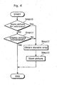
- Fig. 4 is a flowchart showing an operation of the reference picture control unit RefPicCtrl of the present invention.
- the reference picture control unit RefPicCtrl judges whether or not a decoded picture (picture) is to be stored for reference for a predictive image (Step 10). When the decoded picture is to be used for reference, the operation proceeds to Step 12, otherwise to Step 11.
- Step 11 the reference picture control unit RefPicCtrl judges whether or not the decoded picture is immediately displayable.
- "Immediately displayable” here means that the decoded picture can be displayed at the time of being decoded (see for example Picture 1 in Fig. 1).
- the decoded picture which is not immediately displayable means that it needs to be displayed later (for instance, B5 shown in Fig. 1).
- the operation is terminated, otherwise, goes on to Step 12.
- Step 12 the reference picture control unit RefPicCtrl obtains an area capable of storing a picture in the picture memory PicMem2 and instructs to store the decoded picture in the area obtained in the picture memory PicMem2 using a memory control command MMCO in Step 13.
- the picture which is not displayed immediately is stored in the picture memory PicMem2 and can be outputted for display from the picture memory PicMem2 when the time has come for its display.
- This does not require an unnecessary picture memory assigned for a picture for display and a picture that needs to be stored for display can be stored in the picture memory assigned for a picture for reference.
- the picture memory PicMem2 includes an area for reference in which a reference picture is stored for generating a predictive image and an area for display in which a picture for display is sto red.
- a picture size can be modified for each GOP (Group Of Picture) mentioned before.
- the modification of the picture size takes place only when a whole area for reference in the memory storing an unnecessary reference picture is released (make the status of the memory reusable).
- the picture for display that is not yet displayed is stored in the memory area, and it is necessary to determine explicitly a coping strategy of how to handle this picture for display but not yet displayed (whether to delete it or to store it until it is displayed).
- Figs. 5A, 5B and 5C are state diagrams showing the storing status of the pictures in the memory in stages.
- pictures 200a, 200b and 200c are the pictures for reference (the pictures to be used for reference in order to generate a predictive image) whereas pictures 201a, 201b, 201c, 201d, and 201e are the pictures for display (pictures to be displayed and not displayed yet).
- the pictures 201a, 201b, 201c, 201d and 201e will be displayed in the numeric order as shown in Fig. 5A.
- Fig. 5A illustrates the status in which the whole memory areas assigned for the reference pictures 200a, 200b and 200c are released for the reusability.
- Fig. 5B shows that the picture size is modified following the status shown in Fig. 5A.
- a reference picture 202a being modified to a bigger size is stored in the memory area in which the reference picture 200a has been stored. Furthermore, the picture for display 201a is outputted for display and its memory area is released.
- Fig. 5C shows a status in which the memory area storing the picture for display 201b is released after the status shown in Fig. 5B.
- a reference picture 202b being modified into a bigger size is stored in the memory area in which the pictures for display 201a and 201b have been stored and a small memory area 203 is left. Even though the memory area storing the picture for display 201c is released, the reference picture (whose picture size is enlarged) cannot be newly stored.
- the pictures of different picture sizes are mixed in the memory (the reference pictures whose picture sizes are enlarged and the pictures for display which are not yet displayed and whose sizes are not yet modified).
- the memory is used fragmentarily, which produces a small memory area that cannot be used, and the usability is thereby deteriorated.
- the data in the memory is repositioned so that the small memory area caused by the modification of the picture size disappears, the memory access increases greatly and thereby it is difficult to realize encoding and decoding operations in actual time.
- the first method is to release the area for display in which the pictures for display that are not yet displayed are stored and the area for reference in which the reference pictures are stored (as a reusable state) and gives up the display of the pictures for display that are not yet displayed. This can prevent the fragmentary use of the memory caused by the mixture of the pictures of different sizes and thereby the deterioration in the usability of the memory can be reduced.
- the modification in the picture size described above takes place as described in the following.
- the picture size modification unit PicSize shown in Fig. 3 receives the encoding type (I-picture, P-picture and B-picture) of each picture determined by the picture structure determination unit PicStruct and the picture size for the modification inputted from outside and outputs to the reference picture control unit RefPicCtrl an instruction to modify the picture size with the timing to start encoding 1-picture.
- the I-picture is a special I-picture (IDR (Instantaneous Decoding Refresh) picture) to be inserted, for example, in the beginning of the GOP.
- IDR Intelligent Decoding Refresh
- the second method is to switch a method to release the whole area of the memory and discard the pictures for display that are not yet displayed and a method to release only the area for reference in which the reference pictures are stored and display the pictures for display that are not yet displayed before the size modification takes place with a judgment made by a picture decoding apparatus (decoder) for decoding an encoded signal (stream) that is referred to later on so that the display of the pictures for display that are not yet displayed is not obligatory.
- the picture decoding apparatus displays the displayable pictures, for instance, the undamaged pictures according to the display order.
- instruction information indicating one of the following methods: the method to release the whole area of the memory; and the method to release only the area for reference in which the reference picture is stored, or other identifiable information is contained in the stream Str outputted from the picture encoding apparatus 100.
- the processing is operated based on the instruction information placed in the stream.
- a content creator may decide the method according to an application; only the area for reference is released but not the area for display storing a picture for display that is not yet displayed (not releasing the whole area of the memory) when memory can afford to provide the space.
- the picture encoding apparatus can be realized to solve the existing problems.
- the display picture control unit DispPicCtrl shown in Fig. 3 instructs the picture memory PicMem2 not to store a picture newly in the area storing the picture that is not yet displayed, when a picture is stored in the released memory area.
- a picture stored right before can be reproduced as long as a picture is not newly stored (overwritten) in the area.
- Even if a memory area in which the picture that is not yet displayed is released the picture that is not yet displayed and is released at the time of display but is left without being overwritten can be displayed by storing a picture newly not in the memory area but in the area where the picture that is already displayed is stored.
- the picture in the released picture area of the picture memory is called picture for display. "Already displayed” here is practically synonymous with "already outputted to a display device".
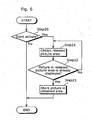
- Fig. 6 is a flowchart showing an operation of the picture encoding apparatus 100 of the present embodiment.
- the present embodiment characterizes in determining the storage of the picture by judging whether the picture stored in the released area in the memory is already displayed or not.
- Step 20 the picture encoding apparatus 100 judges whether or not the decoded picture is to be stored in the picture memory PicMem2 based on the instructions indicated in the memory control command MMCO.
- the released picture area is obtained (Step 21) and whether a picture stored in the released picture area is already displayed or not is verified (Step 22). When it is not yet displayed, the operation goes back to Step 21 and the processing continues until the released area in which the picture already displayed has been stored is found.
- the decoded picture is stored in the area (Step 23).
- the picture that is not yet displayed is stored in the memory without being overwritten until its display time since the area storing the displayed picture is reused.
- Whether a picture stored in the memory is already displayed or not can be judged by the display picture control unit DispPicCtrl managing information on whether or not the picture is displayed.
- Whether a picture area is a released area or not can be judged by referring to the information on whether or not each picture area is released, for instance, "used (usable as a reference picture)" or “unused (no longer used as a reference picture)" stored in the picture memory PicMem2 according to the memory control command MMCO.
- the picture encoding apparatus of the present invention can be realized so as to overcome the existing problems.
- Fig. 7 is a flowchart of an operation of the picture encoding apparatus 100 of the third embodiment of the present invention.
- the present embodiment characterizes in determining the storage of the picture according to the time when the memory is released.
- Step 30 the picture encoding apparatus 100 judges whether or not the decoded picture is to be stored in the picture memory PicMem2 based on the instruction indicated in the memory control command MMCO.
- the released picture memory area whose display time is the earliest within released area is obtained (Step 31) and the decoded picture is stored in the obtained area (Step 32).
- the memory area in which the picture is decoded and stored at the earliest time instead of the memory area released at the earliest display time may be allocated as an area to store the picture. For, there is a high possibility that the pictures stored in these memory areas are already displayed.
- earliest times are not necessarily based on time and may be the earliest time according to an order, for instance, it may be the earliest time according to a display order.
- a picture whose display order is the earliest is already displayed and a memory area storing such picture can be reused in turn as a storing area in the memory regardless of whether it is already displayed or not.
- the intervals of displaying pictures is regular, therefore, the order of displaying pictures may be considered as the display time.
- overwriting of a picture newly onto the picture that is not yet displayed can be prevented so that the latter picture can be outputted for display from the area that is already released but not overwritten at the display time.
- the picture that needs to be stored for display can be stored without requiring an unnecessary memory.
- the processing of storing the picture which needs to be stored for display can be carried out regardless of whether the picture stored in the picture memory PicMem2 is already displayed or not.
- the display picture control unit DispPicCtrl managing the information on whether or not the picture is displayed.
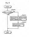
- Fig. 8 is a flowchart showing an operation of the picture encoding apparatus 100 according to the fourth embodiment of the present invention.
- the present embodiment characterizes in determining a storage of the picture according to an order of releasing the memory.
- Step 40 the picture encoding apparatus 100 judges whether or not the decoded picture is to be stored in the picture memory PicMem2 based on the instruction indicated in the memory control command MMCO.
- the picture memory area released at the earliest time within released area is obtained (Step 41) and the decoded picture is stored in the obtained area (Step 42).
- Whether the picture area is a released area or not can be judged by referring to the information on whether or not each picture area is released, for instance, "used (usable as a reference picture)" or “unused (no longer used as a reference picture)” that is stored in the picture memory PicMem2 according to the memory control command MMCO.
- the usage of the picture area can be fixed beforehand to a predetermined procedure in order to judge whether the picture area is the one that is firstly released according to the procedure.
- this can be judged by the picture memory PicMem2 functioning as a memory using a first-in first-out (FIFO) method by which the contents of record whose time records that picture is to be stored newly is sequentially discarded in turn and the latest pictures of a fixed number of frames (or number of pictures) are always stored.
- FIFO first-in first-out
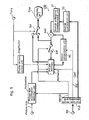
- Fig. 9 is a block diagram of a picture decoding apparatus for realizing the picture decoding method of the present invention.
- the same referential numbers are put for the devices that operate in the same manner as a picture encoding apparatus for realizing the picture encoding method according to the present invention shown in the block diagram of Fig. 3 and a picture decoding apparatus for realizing the conventional picture decoding method shown in the block diagram of Fig. 28 and the explanation is thereby abbreviated.
- the difference between the picture decoding apparatus 150 shown in Fig. 9 and the example of conventional apparatus shown in Fig. 28 is that a picture size modification detection unit PicSizeDet and a display picture control unit DispPicCtrl are newly set.
- the picture size modification detection unit PicSizDet outputs a command to modify the picture size in the timing of starting encoding of a special I-picture (IDR picture) based on the picture size for the modification obtained from outside and the memory control command MMCO obtained from the variable length decoding unit VLD.
- the display picture control unit DispPicCtrl instructs the picture memory PicMem2 not to store a picture newly in the area for the picture that is not yet displayed when storing the new picture in the released area. Normally, even though an area for a picture is released, data of a picture that is stored right before is left in the memory and can be reproduced as long as a picture is not newly stored (overwritten) in the area. The picture that is released at the time of display but left without being overwritten can be displayed by storing a picture newly in the area where the picture that is already displayed is stored even if the memory area in which the picture that is not yet displayed is released. "Already displayed” here is practically synonymous with "already outputted to a display device".
- the picture that is not yet displayed is stored in the memory without being overwritten until its display time since the area storing the displayed picture is reused.
- the picture decoding apparatus 150 may decode an encoded signal that is encoded by the picture encoding apparatus 100 shown in the third and fourth embodiments.
- the operation for the use of the picture memory is as same as the one described for the picture encoding apparatus shown in the third and fourth embodiments. Namely, for the reusability of the picture area that is released (no longer used for reference) in the picture memory, either method of deciding the area for the picture to be newly stored described in the first through third embodiments may be employed.
- the following describes methods of storing the picture in the memory when decoding the encoded signal encoded by the picture encoding apparatus shown in the third and fourth embodiments.
- the picture decoding apparatus 150 judges whether or not the decoded picture outputted from the addition unit Add in the picture decoding apparatus 150 is to be stored in the picture memory PicMem2 based on the instruction indicated in the memory control command MMCO.
- the picture memory area firstly released is obtained and the decoded picture is stored in the obtained area.
- the memory area in which the picture is decoded and stored at the earliest time or the memory area in which the picture with the earliest display time is stored instead of the memory area that is released at the earliest time may be allocated as an area to store the picture. For there is a high possibility that the pictures stored in these memory areas are already displayed.
- the picture with the earliest display time is stored in the area in which the picture is stored at the earliest time than the one in which the picture is stored at the later time. It is with high possibility that the picture stored at the earliest time is already displayed since it is natural that the picture with early display time is already displayed. Therefore, there is a high possibility that the picture that is not displayed yet is not overwritten when the decoded picture is stored in the area in which the picture stored at the earliest time has been stored.
- the earliest time corresponds with the earliest time when the picture is encoded, whether the picture is encoded at the earliest time, for instance, can be judged by the prediction structure and the decoding order of the picture.
- earliest times are not necessarily based on time and may be the earliest time according to an order, for instance, it may be the earliest time according to a display order.
- a picture whose display order is the earliest is already displayed and a memory area storing such picture can be reused in turn as a storing area in the memory regardless of whether it is already displayed or not.
- the intervals of displaying pictures is regular, therefore, the order of displaying pictures may be considered as the display time.
- the processing of storing the picture which needs to be stored for display can be carried out regardless of whether the picture stored in the picture memory PicMem2 is already displayed or not.
- the earliest time indicates the earliest time in display time
- whether or not the picture is stored at the earliest time can be judged by the display picture control unit DispPicCtrl managing the information on whether or not the picture is displayed.
- the following describes a method of storing a picture in the memory when decoding the encoded signal encoded by the picture encoding apparatus shown in the fourth embodiment.
- the picture decoding apparatus 150 judges whether or not the decoded picture outputted from the addition unit Add mentioned above of the picture decoding method 150 is to be stored in the picture memory PicMem2 based on the instruction indicated in the memory control command MMCO.
- the picture memory firstly released is obtained and the decoded picture is stored in the obtained area.
- Whether the picture area is a firstly released picture area or not can be judged by referring to the information on whether or not each picture area is released, for instance, "used (usable as a reference picture)" or “unused (no longer used as a reference picture)", that is stored in the picture memory PicMem2 according to the memory control command MMCO, including the order of releasing the pictures.
- the usage of the picture area can be fixed beforehand to a predetermined procedure in order to judge whether the picture area is the one that is firstly released according to the procedure.
- this can be judged by the picture memory PicMem2 functioning as a memory using a first-in first-out (FIFO) method by which the contents of record with old recording time is sequentially discarded when the new data is recorded so that the latest pictures of a fixed number of frames (or number of pictures) are always stored.
- FIFO first-in first-out
- the display unit Disp may be installed in the exterior of the picture decoding apparatus 150 in stead of being included in it so that the picture decoding apparatus 150 may send only the data necessary for displaying a picture at the display unit Disp.
- a method corresponding to the first method in the case in which the picture size is modified shown in the second embodiment is that the picture decoding apparatus 150 releases a whole area in the memory including the area for reference in which the reference picture is stored and the area for display in which the picture for display is stored and performs initialization when receiving a command to modify the picture size.
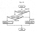
- Fig. 10 is a flowchart showing an operation of the picture encoding apparatus 150.
- the picture encoding apparatus 150 judges whether or not a signal outputted from the picture size modification detection unit PicSizeDet indicates a modification of a picture size (Step 100). When it does (Yes in Step 100), the picture encoding apparatus 150 releases a whole memory area of the picture memory PicMem2 (as a reusable state), initializes it (Step 102) and ends the processing.
- the picture decoding apparatus 150 judges whether or not the memory control command MMCO outputted from the variable length decoding unit VLD indicates the release (initialization) of the whole memory area in the picture memory PicMem2 (Step 101) and if it does (Yes in Step 101), releases the whole memory area (Step 102), if not (No in Step 101), release only the area for reference in which the reference picture is stored (Step 103) and ends the processing.
- the methods are switched from one to the other: a method of releasing the whole area of the memory or a method of releasing only the area for reference in which the reference picture is stored and displaying the displayable picture out of the pictures that are not yet displayed with the judgment made by the picture decoding apparatus 150.
- the instruction information (flag) indicating either to release the whole memory area or to release only the area for reference is contained in the memory control command MMCO in the stream Str outputted from the picture encoding apparatus 100.
- the picture decoding apparatus 150 determines either of the two methods described above based on the instruction information contained in the memory control command MMCO.
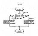
- Fig. 11 is a flowchart showing a determination operation.
- the picture decoding apparatus 150 judges whether or not the instruction information (flag) indicates the initialization of the whole area of the memory (Step 150). When it indicates the initialization of the whole area (Yes in Step 150), the picture decoding apparatus 150 releases the whole area, for initialization, including the area for display storing the picture for display that is not yet displayed (Step 151), otherwise (No in Step 150), releases only the area for reference for initialization (Step 152).
- the picture decoding apparatus 150 releases only the area for reference. As for the picture that is not displayed yet and stored in an area other than the area for reference, the picture decoding apparatus 150 judges the picture and displays the displayable.
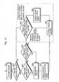
- Fig. 12 is a flowchart showing an operation of the picture decoding apparatus 150 (decoder).
- the picture decoding apparatus 150 judges whether or not the signal outputted from the picture size modification detection unit PicSizeDet indicates a modification of a picture size (Step 200). Unless it indicates the modification of the picture size (No in Step 200), the picture decoding apparatus 150 displays the picture to be displayed that is not yet displayed stored in the area for display (Step 203).
- the picture decoding apparatus 150 determines whether or not the picture for display stored in the area for display is the one before the modification of the size takes place (Step 201). When it is not the case (No in Step 201), the picture decoding apparatus 150 displays the picture to be displayed that is not yet displayed (Step 203). When it is the case (Yes in Step 201), the picture decoding apparatus 150 judges whether or not the picture for display is displayable or not and display it based on the judgment (Step 202)
- the following describes an operation of the picture decoding apparatus 150 for a judgment on whether the picture can be displayed or not.
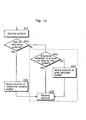
- Fig. 13 is a flowchart showing the operation of the picture decoding apparatus 150 with regards to a display of the picture.
- the picture decoding apparatus 150 judges whether or not the picture for display stored in the area for display is the one before the modification of the size takes place (Step 201). When the picture is not the one before the modification takes place (No in Step 201), the picture decoding apparatus 150 displays the picture. On the other hand, when the picture is the one before the modification takes place (Yes in Step 201), the picture decoding apparatus 150 determines whether the picture to be displayed is damaged or not (Step 211). When the picture is not damaged (No in Step 211) the picture is considered as displayable and thereby displayed (Step 210). When it is damaged (Yes in Step 211), the preceding picture, for instance, is displayed instead.
- not being damaged means that the picture to be displayed is not overwritten so that a new picture data is stored even the picture is a part of a picture being stored.
- the picture decoding apparatus 150 judges whether or not the picture to be displayed is damaged, determines the undamaged picture as displayable and displays it.
- the picture decoding apparatus 150 displays the picture that is not displayed yet according to the instruction information (flag) indicating whether or not to initialize the whole area of the memory when the modification of the picture size takes place.
- an appropriate decoding is realized by switching either to initialize the whole area of the memory or to initialize only the area for reference and display the picture for display that is not yet displayed even when the modification of the picture size is performed. Namely, when the free area in the memory is small, for instance, the whole area in the memory is initialized for reuse whereas when it is large, the case can be handled flexibly by allowing the display of the picture that is not yet displayed after initializing only the area for reference.
- a reference picture buffer is an area combining an area for reference and the one for display in the picture memory PicMem2 in a picture encoding apparatus.
- a virtual display delay buffer is a virtual buffer for each picture for display to be stored in the area for display that is retained in the picture memory PicMem2 in the picture encoding apparatus and stores temporal reference numbers of the pictures for display (picture numbers or the like).
- a reference memory buffer is an area for reference in the picture memory PicMem2 in a picture decoding apparatus.
- a post decoder buffer is an area for display in the picture memory PicMem2 in the picture decoding apparatus.
- the temporal reference numbers are the numbers that are assigned for the pictures according to the order of display time and may be an equivalent of the picture time Time.
- the virtual display delay buffer is used to limit the maximum number of the reference pictures used for predictive encoding performed by the picture encoding apparatus.
- Fig. 14 shows processing of determining a relationship between the virtual display delay buffer and the maximum number of the backward reference pictures.
- Each module in Fig. 14 presents a function block or a processing step of a picture structure determination unit PicStruct, a reference picture control unit RefPicCtrl and a display picture control unit DispPicCtrl.
- the maximum number of the reference pictures allowed, N R for this profile and level is determined in module 401. This value is defined for each profile and level and thereby the encoder encodes the value of profile/level, an equivalent of N R , as information on a stream and a decoder obtains N R according to the value of profile/level in the stream.
- the picture encoding apparatus then set the maximum number of backward reference pictures, N B , optimal for encoding a video sequence in module 402.
- the size of the virtual display delay buffer can be determined based on this N B value. When the N B is less than 2, the virtual display delay buffer is not required. However when N B is greater than or equal to 2, a virtual display delay buffer that can store N B -1 number of pictures is created in module 404. The information on the picture stored in the virtual display delay buffer is retained in the memory or in any register. This virtual display delay buffer does not require a large physical memory space in the picture encoding apparatus.
- Fig. 15 shows the post encoding processing in the picture encoding apparatus, that is, a processing of storing a picture decoded after being encoded (referred to as an encoded picture or simply a picture) in the reference memory buffer.
- the module in the diagram presents a function block or a processing step in the reference picture control unit RefPicCtrl and the display picture control unit DispPicCtrl.
- NMax presents the maximum number of the possible reference pictures
- N R presents the maximum number of the reference pictures allowed in the profile and level definition.
- Fv presents a virtual display delay buffer fullness, that is, the number presently used out of the size of the virtual display delay buffer (N B -1).
- the encoded picture is reconstructed (decoded) in module 506 and stored in the reference picture buffer in module 507.
- the picture encoding apparatus retains a necessary area in the reference picture buffer by removing certain unused reference pictures (no longer used as reference pictures) from the buffer, as shown in module 504.
- the encoded picture is not used as a reference picture.
- the temporal reference number of the encoded picture is compared with the one indicated at the display counter in module 505.
- the virtual display delay buffer When the temporal reference number of the non-reference picture is less than the one indicated at the display counter, the virtual display delay buffer is updated in module 508.
- the virtual display delay buffer removes the picture having the temporal reference number equal to or earlier than the one indicated at the display counter and adds the temporal reference number of the current non-reference picture into the buffer.
- the number of the pictures in the virtual buffer having the temporal reference number less than the one indicated in the display counter becomes the fullness of the buffer.
- the display counter only starts updating operation with initiative when the number of the encoded picture equals to N B or when the virtual display counter is full, no matter which may be earlier. After that, the display counter is updated for every picture that is encoded in module 509.
- Fig. 16 shows the post decoding processing in the picture decoding apparatus, that is, processing of storing a picture decoded by the picture decoding apparatus (referred to as a decoded picture or simply a picture) in the reference picture buffer.
- the modules in the diagram show the function blocks or the processing steps in the display picture control unit DispPicCtrl.
- a picture is decoded in module 601.
- the picture decoding apparatus determines whether or not the picture needs to be stored as a reference picture. If the decoded picture is to be stored as a reference picture, it is stored in the reference picture buffer in module 606, otherwise, the picture decoding apparatus examines whether it is time to display (output) this picture in module 603.
- the picture is stored in the post decoder buffer in module 604 until its display time.
- Both the post decoder buffer and the reference picture buffer share physically the same memory area. In other words, each area of the same memory can be used as a reference picture buffer for some occasions and as a post decoder buffer for other occasions.
- the picture decoding apparatus determines a picture to be displayed (outputted) either from the reference picture buffer or the post decoder buffer based on the display timing. Once a picture from the post decoder buffer is displayed (outputted), it is removed from the buffer. On the other hand, a reference picture is only to be removed from the reference picture buffer or shifted to the post decoder buffer when the stream indicates that the reference picture is no longer used for reference.
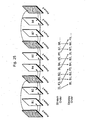
- Fig. 17 is an example of a method using a virtual display delay buffer for determining the maximum number of reference pictures at each picture interval.
- the maximum number of reference pictures allowed, N R shall be 4.
- the picture encoding apparatus sets the maximum number of backward reference pictures, N B , to be 3.
- virtual display delay buffer in which two pictures are storable is generated (the area is retained).
- the display counter is used for storing and updating the temporal reference number of the picture to be virtually displayed (outputted).
- the vacant area shows that the area is vacant
- the area described with its picture type and the number shows that the picture for reference is stored
- the hatched area shows that the picture for display is stored.
- the vacant area shows that the area is vacant
- the area described with its picture type and the number shows that the temporal reference number of the picture for display in the reference memory buffer is stored
- the hatched area shows that the reference memory buffer does not have a storing area for the picture for display.
- the virtual display delay buffer whose number corresponds to the number of the hatched area in the reference memory buffer stores the temporal reference numbers of the pictures for display.
- the pictures B2 and B3 are used as reference pictures and thereby they are stored in the reference memory buffer together with 10 and P4, and the display counter starts updating after the picture B3 is encoded.
- B5 is not used as a reference picture, however, this is because the temporal reference number is greater than the one indicated at the display counter and needs to be updated by the virtual display delay buffer. Therefore, the fullness of the virtual display delay buffer Fv at that time is 1 and the maximum number of possible reference pictures NMax is 3.
- the picture B6 needs to be updated by the virtual display delay buffer whereas B5 cannot be removed yet due to its temporal reference number greater than the one indicated at the display counter.
- NMax at that time indicates 2.
- the reference picture 10 has to be removed from the reference memory buffer due to the insufficient memory. B7 at that time then can be predicted only with the use of P4 and P8.
- Fig. 18 shows an example in which the display counter is firstly incremented using the virtual display delay buffer.
- N R shall be 5 in the example.
- the picture encoding apparatus sets the maximum number of multiple backward reference pictures N B to be 3. Thus a virtual display delay buffer in which two pictures are storable is generated.
- B1, B2, B3 and B4 are not used for reference pictures whereas B7 and B8 are.
- B1 and B2 are therefore stored in the virtual display delay buffer at time T3 in order to wait for the display. Since the virtual display delay buffer is full at time T3, the display counter starts updating at time T3. The reason why the display counter needs to wait at least until the virtual display delay buffer becomes full before it can start updating is that it needs to handle the reordering of the B-pictures that is likely to occur in the picture decoding apparatus.
- the picture decoding apparatus sometimes use a part of the reference picture buffer as a post decoder buffer.
- the picture decoding apparatus therefore operates the reference picture buffer based on a fixed physical memory size of the reference picture buffer so that some parts of the reference picture buffer are used for reference pictures and the rest is used as the post decoder buffer. For example, at time T3, the whole reference picture buffer is used to store reference pictures whereas at time T7, only two areas of the reference picture buffer are used to store the reference pictures of P4 and P8. The rest is used to store post decoder pictures B5 and B6.
- the maximum number of the reference pictures to be used at the picture decoding apparatus side is defined in the profile and level definition for the picture encoding apparatus.
- the picture encoding apparatus therefore can use up to the maximum number of the reference pictures defined by the profile and level.
- the picture encoding apparatus controls the reference pictures and performs encoding so that the same operation can be realized (the number of reference pictures does not surpass the predetermined value) when the picture decoding apparatus operates based on the constraint conditions.
- the picture decoding apparatus has the same number of reference pictures as the picture encoding apparatus does.
- additional memory space is needed for the post decoder buffer.
- N P presents the maximum number of post decoder pictures
- N R presents the maximum number of the reference pictures defined by the profile and level definition.
- the maximum number of post decoder pictures shall be therefore considered in the design of the picture decoding apparatus so that the picture decoding apparatus complies with the profile and level definition.
- the maximum number of the post decoder pictures can be either calculated with the use of the equation (3) or specified in the profile and level definition. Once the maximum number of post decoder pictures is specified in the profile and level definition, the maximum number of backward prediction pictures can be calculated based on equation (4).
- N B N P + 1
- N B presents the maximum number of backward prediction pictures in the reference picture buffer.
- N B presents the minimum memory requirements required by the picture decoding apparatus so as to decode a stream complying with the profile and level definition.
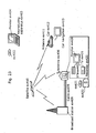
- Fig. 19 is an illustration for realizing the picture encoding/decoding method of the above embodiments using a program recorded onto a storage medium like a flexible disk.
- Fig. 19B shows a full appearance of a flexible disk, its structure at cross section and the flexible disk itself whereas Fig. 19A shows an example of a physical format of the flexible disk as a main body of a storing medium.
- a flexible disk FD1 is contained in a case F, a plurality of tracks Tr are formed concentrically from the periphery to the inside on the surface of the disk, and each track is divided into 16 sectors Se in the angular direction. Therefore, as for the flexible disk storing the above-mentioned program, data as the aforementioned program is stored in an area assigned for it on the flexible disk FD1.
- Fig. 19C shows a structure for recording and reading out the program on the flexible disk FD1.
- the computing system Cs writes in data as the program via a flexible disk drive FDD.
- the picture encoding method and the picture decoding method for realizing the picture encoding method and the picture decoding method as the program on the flexible disk are constructed in the computing system, the program is read out from the flexible disk by the flexible disk drive FDD and then transferred to the computing system Cs.
- the above explanation is made on an assumption that a storing medium is a flexible disk, but the same processing can also be performed using an optical disk.
- the storing medium is not limited to a flexible disk and an optical disk, but any other medium such as an IC card and a ROM cassette capable of recording a program can be used.
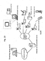
- Fig. 20 is a block diagram showing an overall configuration of a content supply system ex100 for realizing content distribution service.
- the area for providing communication service is divided into cells of desired size, and cell sites ex107 ⁇ ex110 which are fixed wireless stations are placed in respective cells.
- This content supply system ex100 is connected to devices such as Internet ex101, an Internet service provider ex102, a telephone network ex104, as well as a computer ex111, a PDA (Personal Digital Assistant) ex112, a camera ex113, a cell phone ex114 and a cell phone with a camera ex115 via the cell sites ex107 ⁇ ex110.
- devices such as Internet ex101, an Internet service provider ex102, a telephone network ex104, as well as a computer ex111, a PDA (Personal Digital Assistant) ex112, a camera ex113, a cell phone ex114 and a cell phone with a camera ex115 via the cell sites ex107 ⁇ ex110.
- PDA Personal Digital Assistant
- the content supply system ex100 is not limited to the configuration as shown in Fig. 20 and may be connected to a combination of any of them. Also, each device may be connected directly to the telephone network ex104, not through the cell sites ex107 ⁇ ex110.
- the camera ex113 is a device capable of shooting video such as a digital video camera.
- the cell phone ex114 may be a cell phone of any of the following system: a PDC (Personal Digital Communications) system, a CDMA (Code Division Multiple Access) system, a W-CDMA (Wideband-Code Division Multiple Access) system or a GSM (Global System for Mobile Communications) system, a PHS (Personal Handyphone System) or the like.
- a streaming server ex103 is connected to the camera ex113 via the telephone network ex104 and also the cell site ex109, which realizes a live distribution or the like using the camera ex113 based on the coded data transmitted from the user.
- Either the camera ex113 or the server which transmits the data may code the data.
- the picture data shot by a camera ex116 may be transmitted to the streaming server ex103 via the computer ex111.
- either the camera ex116 or the computer ex111 may code the picture data.
- An LSI ex117 included in the computer ex111 or the camera ex116 actually performs encoding processing.
- Software for encoding and decoding pictures may be integrated into any type of storage medium (such as a CD-ROM, a flexible disk and a hard disk) that is a recording medium which is readable by the computer ex111 or the like. Furthermore, a cell phone with a camera ex115 may transmit the picture data. This picture data is the data encoded by the LSI included in the cell phone ex115.
- the content supply system ex100 encodes contents (such as a music live video) shot by a user using the camera ex113, the camera ex116 or the like in the same way as shown in the above-mentioned embodiments and transmits them to the streaming server ex103, while the streaming server ex103 makes stream distribution of the content data to the clients at their requests.
- the clients include the computer ex111, the PDA ex112, the camera ex113, the cell phone ex114 and so on capable of decoding the above-mentioned encoded data.
- the clients can thus receive and reproduce the encoded data, and can further receive, decode and reproduce the data in real time so as to realize personal broadcasting.
- the picture encoding method or the picture decoding method shown in the above-mentioned embodiments can be used.
- FIG. 21 is a diagram showing the cell phone ex115 using the picture encoding method and the picture decoding method explained in the above-mentioned embodiments.
- the cell phone ex115 has an antenna ex201 for communicating with the cell site ex110 via radio waves, a camera unit ex203 such as a CCD camera capable of shooting moving and still pictures, a display unit ex202 such as a liquid crystal display for displaying the data such as decoded pictures and the like shot by the camera unit ex203 or received by the antenna ex201, a body unit including a set of operation keys ex204, a audio output unit ex208 such as a speaker for outputting audio, a audio input unit ex205 such as a microphone for inputting audio, a storage medium ex207 for storing coded or decoded data such as data of moving or still pictures shot by the camera, data of received e-mails and that of moving or still pictures, and a slot unit ex206 for attaching the storage medium ex207 to the cell phone ex115.
- a camera unit ex203 such as a CCD
- the storage medium ex207 stores in itself a flash memory element, a kind of EEPROM (Electrically Erasable and Programmable Read Only Memory) that is a nonvolatile memory electrically erasable from and rewritable to a plastic case such as an SD card, or the like.
- EEPROM Electrically Erasable and Programmable Read Only Memory
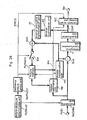
- a main control.unit ex311 designed in order to control overall each unit of the main body which contains the display unit ex202 as well as the operation keys ex204, is connected mutually to a power supply circuit unit ex310, an operation input control unit ex304, a picture encoding unit ex312, a camera interface unit ex303, an LCD (Liquid Crystal Display) control unit ex302, a picture decoding unit ex309, a multiplexing/demultiplexing unit ex308, a read/write unit ex307, a modem circuit unit ex306 and a audio processing unit ex305 via a synchronous bus ex313.
- a power supply circuit unit ex310 an operation input control unit ex304, a picture encoding unit ex312, a camera interface unit ex303, an LCD (Liquid Crystal Display) control unit ex302, a picture decoding unit ex309, a multiplexing/demultiplexing unit ex308, a read/write unit ex307, a modem circuit unit ex306 and a audio processing unit ex305
- the power supply circuit unit ex310 supplies respective units with power from a battery pack so as to activate the camera attached digital cell phone ex115 as a ready state.
- the audio processing unit ex305 converts the audio signals received by the audio input unit ex205 in conversation mode into digital audio data under the control of the main control unit ex311 including a CPU, ROM and RAM, the modem circuit unit ex306 performs spread spectrum processing of the digital audio data, and the communication circuit unit ex301 performs digital-to-analog conversion and frequency transform of the data, so as to transmit it via the antenna ex201.
- the main control unit ex311 including a CPU, ROM and RAM
- the modem circuit unit ex306 performs spread spectrum processing of the digital audio data
- the communication circuit unit ex301 performs digital-to-analog conversion and frequency transform of the data, so as to transmit it via the antenna ex201.
- the communication circuit unit ex301 amplifies the data received by the antenna ex201 in conversation mode and performs frequency transform and analog-to-digital conversion to the data, the modem circuit unit ex306 performs inverse spread spectrum processing of the data, and the audio processing unit ex305 converts it into analog audio data, so as to output it via the audio output unit ex208.
- the text data of the e-mail inputted by operating the operation keys ex204 of the main body is sent out to the main control unit ex311 via the operation input control unit ex304.
- the modem circuit unit ex306 performs spread spectrum processing of the text data
- the communication circuit unit ex301 performs digital-to-analog conversion and frequency transform for the text data
- the data is transmitted to the cell site ex110 via the antenna ex201.
- the picture data shot by the camera unit ex203 is supplied to the picture encoding unit ex312 via the camera interface unit ex303.
- the picture encoding unit ex312 which includes the picture encoding apparatus as explained in the present invention, compresses and codes the picture data supplied from the camera unit ex203 by the encoding method used for the picture encoding apparatus as shown in the above-mentioned first embodiment so as to transform it into encoded picture data, and sends it out to the multiplexing/demultiplexing unit ex308.
- the cell phone ex115 sends out the audio received by the audio input unit ex205 during the shooting with the camera unit ex203 to the multiplexing/demultiplexing unit ex308 as digital audio data via the audio processing unit ex305.
- the multiplexing/demultiplexing unit ex308 multiplexes the encoded picture data supplied from the picture encoding unit ex312 and the audio data supplied from the audio processing unit ex305 using a predetermined method, then the modem circuit unit ex306 performs spread spectrum processing of the multiplexed data obtained as a result of the multiplexing, and lastly the communication circuit unit ex301 performs digital-to-analog conversion and frequency transform of the data for the transmission via the antenna ex201.
- the modem circuit unit ex306 performs inverse spread spectrum processing of the data received from the cell site ex110 via the antenna ex201, and sends out the multiplexed data obtained as a result of the inverse spread spectrum processing.
- the multiplexing/demultiplexing unit ex308 separates the multiplexed data into an encoded stream of picture data and that of audio data, and supplies the encoded picture data to the picture decoding unit ex309 and the audio data to the audio processing unit ex305 respectively via the synchronous bus ex313.
- the picture decoding unit ex309 decodes the encoded stream of picture data using the decoding method corresponding to the encoding method as shown in the above-mentioned embodiments to generate reproduced moving picture data, and supplies this data to the display unit ex202 via the LCD control unit ex302, and thus the picture data included in the moving picture file linked to a Web page, for instance, is displayed.
- the audio processing unit ex305 converts the audio data into analog audio data, and supplies this data to the audio output unit ex208, and thus the audio data included in the moving picture file linked to a Web page, for instance, is reproduced.
- the present invention is not limited to the above-mentioned system as such ground-based or satellite digital broadcasting has been in the news lately and at least either the picture encoding apparatus or the picture decoding apparatus described in the above-mentioned embodiments can be incorporated into a digital broadcasting system as shown in Fig. 23. More specifically, an encoded stream of video information is transmitted from a broadcast station ex409 to or communicated with a broadcast satellite ex410 via radio waves. Upon receipt of it, the broadcast satellite ex410 transmits radio waves for broadcasting. Then, a home-use antenna ex406 with a satellite broadcast reception function receives the radio waves, and a television (receiver) ex401 or a set top box (STB) ex407 decodes the encoded stream for reproduction.
- a television (receiver) ex401 or a set top box (STB) ex407 decodes the encoded stream for reproduction.
- the picture decoding apparatus as shown in the above-mentioned embodiment can be implemented in a reproducing apparatus ex403 for reading out and decoding the encoded stream recorded on a storage medium ex402 that is a recording medium such as CD and DVD.
- the reproduced video signals are displayed on a monitor ex404.
- the picture decoding apparatus in the set top box ex407 connected to a cable ex405 for a cable television or the antenna ex406 for satellite and/or ground-based broadcasting so as to reproduce them on a monitor ex408 of the television ex401.
- the picture decoding apparatus may be incorporated into the television, not in the set top box.
- a car ex412 having an antenna ex411 can receive signals from the satellite ex410 or the cell site ex107 for reproducing moving pictures on a display device such as a car navigation system ex413 set in the car ex412.
- the picture encoding apparatus as shown in the above-mentioned embodiments can encode picture signals and record them on a recording medium.
- a recorder ex420 such as a DVD recorder for recording picture signals on a DVD disk ex421, a disk recorder for recording them on a hard disk, or the like can be cited. They can be recorded on an SD card ex422. If the recorder ex420 includes the picture decoding apparatus as shown in the above-mentioned embodiments, the picture signals recorded on the DVD disk ex421 or the SD card ex422 can be reproduced for display on the monitor ex408.
- the structure of the car navigation system ex413 the structure without the camera unit ex203, the camera interface unit ex303 and the picture encoding unit ex312, out of the components shown in Fig. 22, for example, is conceivable.
- a terminal such as the above-mentioned cell phone ex114; a sending/receiving terminal implemented with both an encoder and a decoder, a sending terminal implemented with an encoder only, and a receiving terminal implemented with a decoder only.
- the term "display” means to output after reordering the order of the pictures into a display order. Namely, a process for outputting a decoded picture to a display device is described as "display”. An operation of outputting the decoded picture in order to record it onto other recording device, for instance, applies to this special usage of "display”.
- the display device has a picture memory, it is possible to transmit the decoded picture to the display device earlier than the actual display time.
- the present invention is used for a picture encoding apparatus for encoding a picture by a predictive encoding with reference to a decoded picture stored in a decoded picture buffer, decoding the encoded picture and storing the decoded picture in the decoded picture buffer and a picture encoding apparatus for decoding the picture encoded by a predictive encoding with reference to a decoded picture stored in a decoded picture buffer and storing the decoded picture in the decoded picture buffer.
Claims (2)
- Dekodierverfahren zum Dekodieren eines prädiktionskodierten Bildsignals eines Bewegtbildsignals, das aus einer Vielzahl von Bildern zusammengesetzt ist, wobei das kodierte Bildsignal ein kodiertes Bild enthält, auf das bei der Prädiktionskodierung von einem vorherigen Bild in einer vorbestimmten Anzeigereihenfolge zum Anzeigen der dekodierten Bilder Bezug genommen wird, mit:Dekodieren des kodierten Bildsignals, um ein dekodiertes Bild zu erhalten, Entscheiden (602), ob das dekodierte Bild ein Referenzbild oder ein Nicht-Referenzbild ist basierend auf dem kodierten Bildsignal, wobei ein Referenzbild ein Bild ist, auf das bei der Prädiktionskodierung von einem anderen Bild Bezug genommen wird, und wobei ein Nicht-Referenzbild ein Bild ist, auf das bei der Prädiktionskodierung nicht von einem anderen Bild Bezug genommen wird, undSpeichern (606), für den Fall, dass das dekodierte Bild ein Referenzbild ist, des dekodierten Bildes in einem Zwischenspeicher,gekennzeichnet durch:Entscheiden (603), für den Fall, dass das dekodierte Bild ein Nicht-Referenzbild ist, ob das dekodierte Nicht-Referenzbild gemäß der vorbestimmten Anzeigereihenfolge vor allen dekodierten Bildern, die derzeit in dem Zwischenspeicher gespeichert sind, angezeigt werden kann oder nicht, undSpeichern (604), für den Fall, dass das dekodierte Nicht-Referenzbild gemäß der vorbestimmten Anzeigereihenfolge nicht vor allen dekodierten Bildern, die derzeit in dem Zwischenspeicher gespeichert sind, angezeigt werden kann, des dekodierten Nicht-Referenzbildes in dem Zwischenspeicher, ohne das dekodierte Nicht-Referenzbild auszugeben.
- Dekodiervorrichtung, die ausgestaltet ist zum Dekodieren eines prädiktionskodierten Bildsignals eines Bewegtbildsignals, das aus einer Vielzahl von Bildern zusammengesetzt ist, wobei das kodierte Bildsignal ein kodiertes Bild enthält, auf das bei der Prädiktionskodierung von einem vorherigen Bild in einer vorbestimmten Anzeigereihenfolge zum Anzeigen der dekodierten Bilder Bezug genommen wird, mit:einer Dekodiereinheit (VLD) zum Dekodieren des kodierten Bildsignals, um ein dekodiertes Bild zu erhalten,einer Entscheidungseinheit (DispPicCtri) zum Entscheiden, ob das dekodierte Bild ein Referenzbild oder ein Nicht-Referenzbild ist basierend auf dem kodierten Bildsignal, wobei ein Referenzbild ein Bild ist, auf das bei der Prädiktionskodierung von einem anderen Bild Bezug genommen wird, und wobei ein Nicht-Referenzbild ein Bild ist, auf das bei der Prädiktionskodierung nicht von einem anderen Bild Bezug genommen wird,einem Zwischenspeicher (PicMem2) zum Speichern des dekodierten Bildes,einer Speichereinheit (PicMem2) zum Speichern, für den Fall, dass das dekodierte Bild ein Referenzbild ist, des dekodierten Bildes in dem Zwischenspeicher,gekennzeichnet durch:eine Entscheidungseinheit (DispPicCtrl) zum Entscheiden, für den Fall, dass das dekodierte Bild ein Nicht-Referenzbild ist, ob das dekodierte Nicht-Referenzbild gemäß der vorbestimmten Anzeigereihenfolge vor allen dekodierten Bildern, die derzeit in dem Zwischenspeicher gespeichert sind, angezeigt werden kann oder nicht, undwobei die Speichereinheit (PicMem2) ferner ausgestaltet ist zum Speichern, für den Fall, dass das dekodierte Nicht-Referenzbild gemäß der vorbestimmten Anzeigereihenfolge nicht vor allen dekodierten Bildern, die derzeit in dem Zwischenspeicher gespeichert sind, angezeigt werden kann, des dekodierten Nicht-Referenzbildes in dem Zwischenspeicher, ohne das dekodierte Nicht-Referenzbild auszugeben.
Priority Applications (5)
| Application Number | Priority Date | Filing Date | Title |
|---|---|---|---|
| SI200330629T SI1406451T1 (sl) | 2002-07-11 | 2003-07-07 | Postopek za kodiranje in dekodiranje slike za H.264, ki uporablja virtualni prikazovalni vmesni spomin |
| EP20060122290 EP1742480B1 (de) | 2002-07-11 | 2003-07-07 | Virtuelles Anzeigepufferverfahren zur Decodierung von H.264 prediktion Bildern. |
| EP20100179945 EP2278816B1 (de) | 2002-07-11 | 2003-07-07 | Post Dekodierer Puffer Verfahren für einen H.264-SVC MPEG Bitstrom. |
| EP20090152597 EP2053863B1 (de) | 2002-07-11 | 2003-07-07 | Video Dekodiereranzeigepuffer mit Wiederbenutzung des vorherigen Bildes im Falle von Bildredimmensionierung. |
| EP20060122279 EP1742479B1 (de) | 2002-07-11 | 2003-07-07 | Virtuellen Multi-hypothesen B-Bild Anzeigepuffer mittels Stehlen von Platz aus dem H.264 Postdekoderpuffer. |
Applications Claiming Priority (7)
| Application Number | Priority Date | Filing Date | Title |
|---|---|---|---|
| JP2002202781 | 2002-07-11 | ||
| JP2002202781 | 2002-07-11 | ||
| JP2002207681 | 2002-07-17 | ||
| JP2002207681 | 2002-07-17 | ||
| JP2003006198 | 2003-01-14 | ||
| JP2003006198 | 2003-01-14 | ||
| PCT/JP2003/008576 WO2004008774A1 (ja) | 2002-07-11 | 2003-07-07 | 画像符号化方法及び画像復号化方法 |
Related Child Applications (2)
| Application Number | Title | Priority Date | Filing Date |
|---|---|---|---|
| EP20060122279 Division EP1742479B1 (de) | 2002-07-11 | 2003-07-07 | Virtuellen Multi-hypothesen B-Bild Anzeigepuffer mittels Stehlen von Platz aus dem H.264 Postdekoderpuffer. |
| EP20060122290 Division EP1742480B1 (de) | 2002-07-11 | 2003-07-07 | Virtuelles Anzeigepufferverfahren zur Decodierung von H.264 prediktion Bildern. |
Publications (3)
| Publication Number | Publication Date |
|---|---|
| EP1406451A1 EP1406451A1 (de) | 2004-04-07 |
| EP1406451A4 EP1406451A4 (de) | 2004-07-07 |
| EP1406451B1 true EP1406451B1 (de) | 2007-01-03 |
Family
ID=30118918
Family Applications (5)
| Application Number | Title | Priority Date | Filing Date |
|---|---|---|---|
| EP20100179945 Expired - Lifetime EP2278816B1 (de) | 2002-07-11 | 2003-07-07 | Post Dekodierer Puffer Verfahren für einen H.264-SVC MPEG Bitstrom. |
| EP20030741225 Expired - Lifetime EP1406451B1 (de) | 2002-07-11 | 2003-07-07 | Verfahren zur Codierung und Decodierung von H.264 Bildern mittels eines virtuellen Anzeigepuffers. |
| EP20090152597 Expired - Lifetime EP2053863B1 (de) | 2002-07-11 | 2003-07-07 | Video Dekodiereranzeigepuffer mit Wiederbenutzung des vorherigen Bildes im Falle von Bildredimmensionierung. |
| EP20060122279 Expired - Lifetime EP1742479B1 (de) | 2002-07-11 | 2003-07-07 | Virtuellen Multi-hypothesen B-Bild Anzeigepuffer mittels Stehlen von Platz aus dem H.264 Postdekoderpuffer. |
| EP20060122290 Expired - Lifetime EP1742480B1 (de) | 2002-07-11 | 2003-07-07 | Virtuelles Anzeigepufferverfahren zur Decodierung von H.264 prediktion Bildern. |
Family Applications Before (1)
| Application Number | Title | Priority Date | Filing Date |
|---|---|---|---|
| EP20100179945 Expired - Lifetime EP2278816B1 (de) | 2002-07-11 | 2003-07-07 | Post Dekodierer Puffer Verfahren für einen H.264-SVC MPEG Bitstrom. |
Family Applications After (3)
| Application Number | Title | Priority Date | Filing Date |
|---|---|---|---|
| EP20090152597 Expired - Lifetime EP2053863B1 (de) | 2002-07-11 | 2003-07-07 | Video Dekodiereranzeigepuffer mit Wiederbenutzung des vorherigen Bildes im Falle von Bildredimmensionierung. |
| EP20060122279 Expired - Lifetime EP1742479B1 (de) | 2002-07-11 | 2003-07-07 | Virtuellen Multi-hypothesen B-Bild Anzeigepuffer mittels Stehlen von Platz aus dem H.264 Postdekoderpuffer. |
| EP20060122290 Expired - Lifetime EP1742480B1 (de) | 2002-07-11 | 2003-07-07 | Virtuelles Anzeigepufferverfahren zur Decodierung von H.264 prediktion Bildern. |
Country Status (18)
| Country | Link |
|---|---|
| US (12) | US7206347B2 (de) |
| EP (5) | EP2278816B1 (de) |
| JP (8) | JP4651685B2 (de) |
| KR (3) | KR100959969B1 (de) |
| CN (2) | CN100361535C (de) |
| AT (4) | ATE548856T1 (de) |
| AU (1) | AU2003281129B2 (de) |
| BR (2) | BR0305432A (de) |
| CA (1) | CA2460471C (de) |
| DE (3) | DE60324480D1 (de) |
| DK (3) | DK2278816T3 (de) |
| ES (4) | ES2420583T3 (de) |
| MX (1) | MXPA04001979A (de) |
| MY (1) | MY135048A (de) |
| PT (2) | PT2278816E (de) |
| SI (2) | SI1406451T1 (de) |
| TW (10) | TWI379595B (de) |
| WO (1) | WO2004008774A1 (de) |
Families Citing this family (34)
| Publication number | Priority date | Publication date | Assignee | Title |
|---|---|---|---|---|
| US7339955B2 (en) * | 2000-09-25 | 2008-03-04 | Pulse-Link, Inc. | TDMA communication method and apparatus using cyclic spreading codes |
| EP3310049B1 (de) * | 2001-11-06 | 2019-01-30 | Panasonic Intellectual Property Corporation of America | Verfahren zur codierung bewegter bilder und verfahren zur decodierung bewegter bilder |
| ES2420583T3 (es) * | 2002-07-11 | 2013-08-26 | Panasonic Corporation | Gestión de memoria intermedia de postdescodificador para un flujo de bits MPEG H.264-SVC |
| JP3513148B1 (ja) * | 2002-10-11 | 2004-03-31 | 株式会社エヌ・ティ・ティ・ドコモ | 動画像符号化方法、動画像復号方法、動画像符号化装置、動画像復号装置、動画像符号化プログラム、及び動画像復号プログラム |
| US7400683B2 (en) * | 2003-11-18 | 2008-07-15 | Lsi Corporation | Device with virtual tilized image memory |
| US7590059B2 (en) * | 2004-05-21 | 2009-09-15 | Broadcom Corp. | Multistandard video decoder |
| US7751324B2 (en) * | 2004-11-19 | 2010-07-06 | Nokia Corporation | Packet stream arrangement in multimedia transmission |
| CN100579223C (zh) * | 2004-12-02 | 2010-01-06 | 索尼株式会社 | 编码装置和方法 |
| WO2006078594A1 (en) * | 2005-01-19 | 2006-07-27 | Thomson Licensing | Method and apparatus for real time parallel encoding |
| US8498340B2 (en) * | 2006-04-04 | 2013-07-30 | Himax Technologies Limited | Method and device for decoding and displaying video frames |
| US7949054B2 (en) | 2006-06-01 | 2011-05-24 | Microsoft Corporation | Flexible data organization for images |
| WO2008018626A2 (en) * | 2006-08-10 | 2008-02-14 | Canon Kabushiki Kaisha | Image decoding apparatus |
| JP2008124772A (ja) * | 2006-11-13 | 2008-05-29 | Hitachi Ltd | 符号化装置及び符号化方法 |
| JP5008484B2 (ja) * | 2007-07-11 | 2012-08-22 | 株式会社日立国際電気 | 映像処理方法 |
| US8503527B2 (en) | 2008-10-03 | 2013-08-06 | Qualcomm Incorporated | Video coding with large macroblocks |
| CN102118537B (zh) * | 2009-12-31 | 2015-04-15 | 深圳富泰宏精密工业有限公司 | 图片错误隐藏系统及方法 |
| JP2011199396A (ja) * | 2010-03-17 | 2011-10-06 | Ntt Docomo Inc | 動画像予測符号化装置、動画像予測符号化方法、動画像予測符号化プログラム、動画像予測復号装置、動画像予測復号方法、及び動画像予測復号プログラム |
| US9491483B2 (en) * | 2010-04-16 | 2016-11-08 | Sk Telecom Co., Ltd. | Inter-prediction method and video encoding/decoding method using the inter-prediction method |
| KR101750495B1 (ko) * | 2010-04-16 | 2017-06-27 | 에스케이텔레콤 주식회사 | 인터 예측 방법 및 그 인터 예측 방법을 이용한 동영상 부호화/복호화 방법 |
| JP5919564B2 (ja) * | 2011-03-10 | 2016-05-18 | パナソニックIpマネジメント株式会社 | 映像処理装置及びそれを用いた映像表示装置、並びに同期信号出力方法 |
| EP3410725B1 (de) | 2011-06-30 | 2021-07-28 | Telefonaktiebolaget LM Ericsson (publ) | Referenzbildsignalisierung |
| CN107197301B (zh) * | 2011-09-09 | 2020-03-03 | Lg 电子株式会社 | 帧间预测方法及其装置 |
| US9237356B2 (en) | 2011-09-23 | 2016-01-12 | Qualcomm Incorporated | Reference picture list construction for video coding |
| JP5698644B2 (ja) * | 2011-10-18 | 2015-04-08 | 株式会社Nttドコモ | 動画像予測符号化方法、動画像予測符号化装置、動画像予測符号化プログラム、動画像予測復号方法、動画像予測復号装置及び動画像予測復号プログラム |
| US9264717B2 (en) | 2011-10-31 | 2016-02-16 | Qualcomm Incorporated | Random access with advanced decoded picture buffer (DPB) management in video coding |
| US9473752B2 (en) | 2011-11-30 | 2016-10-18 | Qualcomm Incorporated | Activation of parameter sets for multiview video coding (MVC) compatible three-dimensional video coding (3DVC) |
| CN107197312B (zh) | 2012-04-23 | 2020-09-01 | Lg 电子株式会社 | 视频解码方法以及实现该方法的装置 |
| CN103389879B (zh) * | 2012-05-10 | 2016-08-17 | 慧荣科技股份有限公司 | 电子装置以及由电子装置传送数据至显示设备的方法 |
| US9762903B2 (en) * | 2012-06-01 | 2017-09-12 | Qualcomm Incorporated | External pictures in video coding |
| WO2014002899A1 (ja) | 2012-06-29 | 2014-01-03 | ソニー株式会社 | 符号化装置および符号化方法 |
| US20160041996A1 (en) | 2014-08-11 | 2016-02-11 | Netapp, Inc. | System and method for developing and implementing a migration plan for migrating a file system |
| CN105917651B (zh) * | 2014-05-30 | 2019-05-14 | 富士通株式会社 | 图像编码方法、装置以及图像处理设备 |
| WO2017033353A1 (ja) * | 2015-08-25 | 2017-03-02 | 川崎重工業株式会社 | 遠隔操作ロボットシステム |
| US10404979B2 (en) * | 2016-03-17 | 2019-09-03 | Mediatek Inc. | Video coding with interpolated reference pictures |
Family Cites Families (60)
| Publication number | Priority date | Publication date | Assignee | Title |
|---|---|---|---|---|
| JPS6230376A (ja) | 1985-07-31 | 1987-02-09 | Fujitsu Ltd | 薄膜トランジスタの製造方法 |
| JP2969782B2 (ja) * | 1990-05-09 | 1999-11-02 | ソニー株式会社 | 符号化データ編集方法及び符号化データ編集装置 |
| JPH05137131A (ja) * | 1991-11-13 | 1993-06-01 | Sony Corp | フレーム間動き予測方法 |
| JPH05308622A (ja) * | 1992-04-28 | 1993-11-19 | Mitsubishi Electric Corp | 画像符号化・復号化装置 |
| JP3189257B2 (ja) * | 1992-05-21 | 2001-07-16 | ソニー株式会社 | 画像符号器 |
| JPH0638197A (ja) * | 1992-06-30 | 1994-02-10 | Sony Corp | 符号器、復号器、および符号化方法 |
| US5398072A (en) * | 1993-10-25 | 1995-03-14 | Lsi Logic Corporation | Management of channel buffer in video decoders |
| US5892882A (en) * | 1994-03-23 | 1999-04-06 | Pioneer Electronic Corporation | Moving picture decoding device having a compressed picture data memory |
| US6009231A (en) * | 1994-09-05 | 1999-12-28 | Sony Corporation | Reproduction of information using a ring buffer with read and write pointers separated from each other by substantially half of the total ring buffer capacity |
| TW330263B (en) * | 1994-10-12 | 1998-04-21 | Winbond Electronics Corp | Digital video decoding system and method |
| JP3694912B2 (ja) * | 1995-02-23 | 2005-09-14 | 株式会社日立製作所 | メモリ制御方法及び画像復号装置 |
| US5724446A (en) | 1995-04-18 | 1998-03-03 | Advanced Micro Devices, Inc. | Video decoder apparatus using non-reference frame as an additional prediction source and method therefor |
| TW257848B (en) * | 1995-04-19 | 1995-09-21 | Silicon Integrated Sys Corp | Adaptive display memory management system and method thereof |
| JP3704356B2 (ja) * | 1995-07-21 | 2005-10-12 | 株式会社 日立製作所 | 符号化映像信号の復号化装置およびそれを用いた蓄積復号化装置 |
| DE69615528T2 (de) * | 1995-09-20 | 2002-05-08 | Koninkl Philips Electronics Nv | Verfahren und vorrichtung zur dekodierung von digitalen videosignalen |
| US5764921A (en) * | 1995-10-26 | 1998-06-09 | Motorola | Method, device and microprocessor for selectively compressing video frames of a motion compensated prediction-based video codec |
| JP3535297B2 (ja) * | 1996-01-26 | 2004-06-07 | ローム株式会社 | 画像データ復号方法およびこの方法を用いた画像データ復号装置 |
| JP3183155B2 (ja) * | 1996-03-18 | 2001-07-03 | 株式会社日立製作所 | 画像復号化装置、及び、画像復号化方法 |
| WO1997035422A1 (en) * | 1996-03-19 | 1997-09-25 | Mitsubishi Denki Kabushiki Kaisha | Encoder, decoder and methods used therefor |
| JPH1013841A (ja) * | 1996-06-20 | 1998-01-16 | Oki Electric Ind Co Ltd | 画像復号方法および画像復号装置 |
| JPH1013791A (ja) * | 1996-06-24 | 1998-01-16 | Matsushita Electric Ind Co Ltd | 映像信号復号化方法,及び映像信号復号化装置 |
| TW351903B (en) * | 1996-07-03 | 1999-02-01 | Matsushita Electric Ind Co Ltd | Encoding method, encoding apparatus, decoding and compositing method, decoding and composition appratus, and record medium recorded with the aforesaid methods for multiple images |
| AU718453B2 (en) * | 1996-07-17 | 2000-04-13 | Sony Corporation | Image coding and decoding using mapping coefficients corresponding to class information of pixel blocks |
| US6006231A (en) * | 1996-09-10 | 1999-12-21 | Warp 10 Technologies Inc. | File format for an image including multiple versions of an image, and related system and method |
| US6104752A (en) * | 1996-10-01 | 2000-08-15 | Victor Company Of Japan, Ltd. | Apparatus and method of decoding high efficiency coded picture data with picture size resizing |
| US5909224A (en) * | 1996-10-18 | 1999-06-01 | Samsung Electronics Company, Ltd. | Apparatus and method for managing a frame buffer for MPEG video decoding in a PC environment |
| US6002438A (en) * | 1996-10-25 | 1999-12-14 | Texas Instruments Incorporated | Method and apparatus for storing decoded video information |
| JP3599942B2 (ja) * | 1997-02-13 | 2004-12-08 | 三洋電機株式会社 | 動画像符号化方法、及び動画像符号化装置 |
| JPH10257499A (ja) | 1997-03-17 | 1998-09-25 | Matsushita Electric Ind Co Ltd | 動画像符号化装置および方法 |
| JPH10322643A (ja) | 1997-03-19 | 1998-12-04 | Fujitsu Ltd | 画像データ処理方法及び装置 |
| JP3373130B2 (ja) | 1997-03-24 | 2003-02-04 | 沖電気工業株式会社 | 画像復号化装置 |
| DE19727542A1 (de) * | 1997-06-28 | 1999-01-07 | Thomson Brandt Gmbh | Verfahren zur Regenerierung der Originaldaten eines digital codierten Videofilms und Vorrichtung zur Durchführung des Verfahrens |
| JPH1141605A (ja) | 1997-07-17 | 1999-02-12 | Nippon Telegr & Teleph Corp <Ntt> | 画像符号化装置および画像復号装置 |
| JP4010024B2 (ja) * | 1997-09-02 | 2007-11-21 | ソニー株式会社 | 圧縮動画像信号のデコード装置 |
| KR100301826B1 (ko) * | 1997-12-29 | 2001-10-27 | 구자홍 | 비디오디코더 |
| US6959045B2 (en) * | 1997-12-30 | 2005-10-25 | Mediatek, Inc. | Reduced cost decoder using bitstream editing for image cropping |
| JPH11275580A (ja) * | 1998-03-24 | 1999-10-08 | Sony Corp | 画像データ処理装置、画像データ復号装置及び画像データ符号化装置並びにそれらの方法 |
| KR100284696B1 (ko) * | 1998-06-29 | 2001-03-15 | 윤종용 | Mpeg 복호 블럭에서의 수평/수직 주파수 변환장치 |
| JP2000050272A (ja) | 1998-07-31 | 2000-02-18 | Sony Corp | 復号化装置及び方法 |
| JP2000059794A (ja) | 1998-08-14 | 2000-02-25 | Nippon Telegr & Teleph Corp <Ntt> | 画像符号化データ作成方法,そのプログラム記憶媒体,画像符号化データ作成装置,画像通信方法および画像通信システム |
| FR2782437B1 (fr) * | 1998-08-14 | 2000-10-13 | Thomson Multimedia Sa | Procede de commutation de flux mpeg |
| US6243140B1 (en) | 1998-08-24 | 2001-06-05 | Hitachi America, Ltd | Methods and apparatus for reducing the amount of buffer memory required for decoding MPEG data and for performing scan conversion |
| US6490324B1 (en) * | 1998-12-08 | 2002-12-03 | Stmicroelectronics, Inc. | System, method and apparatus for a variable output video decoder |
| JP2000232649A (ja) * | 1998-12-10 | 2000-08-22 | Fujitsu Ltd | Mpegビデオ復号器及びmpegビデオ復号方法 |
| US6658056B1 (en) * | 1999-03-30 | 2003-12-02 | Sony Corporation | Digital video decoding, buffering and frame-rate converting method and apparatus |
| JP2000324484A (ja) | 1999-05-13 | 2000-11-24 | Hitachi Ltd | 画像データ処理装置 |
| JP2001094941A (ja) * | 1999-09-27 | 2001-04-06 | Matsushita Electric Ind Co Ltd | 圧縮画像処理装置及び圧縮画像処理方法 |
| JP2001223987A (ja) * | 1999-11-11 | 2001-08-17 | Matsushita Electric Ind Co Ltd | メモリ管理方法、画像符号化方法、画像復号化方法、画像表示方法、メモリ管理装置、メモリ管理プログラム記録媒体 |
| US6836273B1 (en) | 1999-11-11 | 2004-12-28 | Matsushita Electric Industrial Co., Ltd. | Memory management method, image coding method, image decoding method, image display method, memory management apparatus, and memory management program storage medium |
| US6697426B1 (en) * | 2000-03-17 | 2004-02-24 | Koninklijke Philips Electronics N.V. | Reduction of layer-decoding complexity by reordering the transmission of enhancement layer frames |
| EP1156674A1 (de) * | 2000-05-19 | 2001-11-21 | THOMSON multimedia | Verfahren und Vorrichtung zur Dekodierung eines Videodatenstroms in besondere Wiedergabebetriebsarten |
| EP1347651A1 (de) * | 2000-12-20 | 2003-09-24 | Mitsubishi Denki Kabushiki Kaisha | Verfahren und vorrichtung zur dekodierung von bewegungsvideobildern |
| US6680973B2 (en) * | 2001-03-29 | 2004-01-20 | Koninklijke Philips Electronics N.V. | Scalable MPEG-2 video decoder with selective motion compensation |
| JP2003274412A (ja) * | 2002-03-14 | 2003-09-26 | Matsushita Electric Ind Co Ltd | 画像符号化方法および画像復号化方法 |
| ES2420583T3 (es) * | 2002-07-11 | 2013-08-26 | Panasonic Corporation | Gestión de memoria intermedia de postdescodificador para un flujo de bits MPEG H.264-SVC |
| US7822120B2 (en) * | 2002-07-26 | 2010-10-26 | Panasonic Corporation | Moving picture encoding method, moving picture decoding method, and recording medium |
| JP3554729B2 (ja) * | 2002-07-30 | 2004-08-18 | 沖電気工業株式会社 | 画像処理装置 |
| KR100543453B1 (ko) * | 2003-04-24 | 2006-01-23 | 삼성전자주식회사 | 디지털 비디오 스트림의 역재생시 비트율을 제어하기 위한 장치 및 그 방법 |
| JP4281720B2 (ja) * | 2004-10-26 | 2009-06-17 | ソニー株式会社 | データ処理装置、データ処理方法、データ処理システム、プログラムおよび記録媒体 |
| JP5328329B2 (ja) | 2008-12-10 | 2013-10-30 | キヤノン株式会社 | インクジェット記録装置 |
-
2003
- 2003-07-07 ES ES10179945T patent/ES2420583T3/es not_active Expired - Lifetime
- 2003-07-07 AT AT09152597T patent/ATE548856T1/de active
- 2003-07-07 DE DE60324480T patent/DE60324480D1/de not_active Expired - Lifetime
- 2003-07-07 KR KR1020087016264A patent/KR100959969B1/ko active IP Right Grant
- 2003-07-07 BR BR0305432A patent/BR0305432A/pt active IP Right Grant
- 2003-07-07 BR BRPI0305432-2A patent/BRPI0305432B1/pt unknown
- 2003-07-07 EP EP20100179945 patent/EP2278816B1/de not_active Expired - Lifetime
- 2003-07-07 ES ES06122290T patent/ES2317444T3/es not_active Expired - Lifetime
- 2003-07-07 SI SI200330629T patent/SI1406451T1/sl unknown
- 2003-07-07 AU AU2003281129A patent/AU2003281129B2/en not_active Expired
- 2003-07-07 EP EP20030741225 patent/EP1406451B1/de not_active Expired - Lifetime
- 2003-07-07 MX MXPA04001979A patent/MXPA04001979A/es active IP Right Grant
- 2003-07-07 DK DK10179945T patent/DK2278816T3/da active
- 2003-07-07 EP EP20090152597 patent/EP2053863B1/de not_active Expired - Lifetime
- 2003-07-07 CN CNB038010216A patent/CN100361535C/zh not_active Expired - Lifetime
- 2003-07-07 PT PT101799450T patent/PT2278816E/pt unknown
- 2003-07-07 CA CA2460471A patent/CA2460471C/en not_active Expired - Lifetime
- 2003-07-07 ES ES03741225T patent/ES2277092T3/es not_active Expired - Lifetime
- 2003-07-07 PT PT06122279T patent/PT1742479E/pt unknown
- 2003-07-07 SI SI200331669T patent/SI1742479T1/sl unknown
- 2003-07-07 AT AT03741225T patent/ATE350861T1/de active
- 2003-07-07 DK DK03741225T patent/DK1406451T3/da active
- 2003-07-07 DE DE60329427T patent/DE60329427D1/de not_active Expired - Lifetime
- 2003-07-07 EP EP20060122279 patent/EP1742479B1/de not_active Expired - Lifetime
- 2003-07-07 WO PCT/JP2003/008576 patent/WO2004008774A1/ja active IP Right Grant
- 2003-07-07 ES ES06122279T patent/ES2330555T3/es not_active Expired - Lifetime
- 2003-07-07 DK DK06122279T patent/DK1742479T3/da active
- 2003-07-07 EP EP20060122290 patent/EP1742480B1/de not_active Expired - Lifetime
- 2003-07-07 AT AT06122279T patent/ATE443972T1/de not_active IP Right Cessation
- 2003-07-07 US US10/481,012 patent/US7206347B2/en not_active Expired - Lifetime
- 2003-07-07 AT AT06122290T patent/ATE413067T1/de active
- 2003-07-07 CN CN2007101995286A patent/CN101179733B/zh not_active Expired - Lifetime
- 2003-07-07 KR KR1020087016263A patent/KR100961036B1/ko active IP Right Grant
- 2003-07-07 KR KR20047001256A patent/KR100961037B1/ko active IP Right Grant
- 2003-07-07 DE DE2003610842 patent/DE60310842T2/de not_active Expired - Lifetime
- 2003-07-10 TW TW95140990A patent/TWI379595B/zh not_active IP Right Cessation
- 2003-07-10 MY MYPI20032598 patent/MY135048A/en unknown
- 2003-07-10 TW TW95140993A patent/TWI320664B/zh not_active IP Right Cessation
- 2003-07-10 TW TW104117443A patent/TWI575946B/zh not_active IP Right Cessation
- 2003-07-10 TW TW92118870A patent/TWI280058B/zh not_active IP Right Cessation
- 2003-07-10 TW TW104117188A patent/TWI573446B/zh not_active IP Right Cessation
- 2003-07-10 TW TW99128648A patent/TWI414187B/zh not_active IP Right Cessation
- 2003-07-10 TW TW104117448A patent/TWI573447B/zh not_active IP Right Cessation
- 2003-07-10 TW TW104117185A patent/TWI573442B/zh not_active IP Right Cessation
- 2003-07-10 TW TW102134575A patent/TWI492636B/zh not_active IP Right Cessation
- 2003-07-10 TW TW106101249A patent/TWI638565B/zh not_active IP Right Cessation
-
2006
- 2006-11-30 US US11/605,958 patent/US7995658B2/en active Active
-
2007
- 2007-10-23 US US11/976,272 patent/US8189680B2/en active Active
- 2007-10-23 US US11/976,273 patent/US8073059B2/en active Active
- 2007-10-23 US US11/976,271 patent/US8155206B2/en active Active
-
2008
- 2008-02-20 JP JP2008039014A patent/JP4651685B2/ja not_active Expired - Lifetime
-
2009
- 2009-02-13 JP JP2009031922A patent/JP4914459B2/ja not_active Expired - Lifetime
-
2010
- 2010-08-20 JP JP2010185425A patent/JP4914515B2/ja not_active Expired - Lifetime
- 2010-08-25 JP JP2010188860A patent/JP5037657B2/ja not_active Expired - Lifetime
-
2012
- 2012-02-24 JP JP2012039329A patent/JP5412538B2/ja not_active Expired - Lifetime
- 2012-05-01 US US13/461,237 patent/US8660192B2/en not_active Expired - Lifetime
-
2013
- 2013-09-02 JP JP2013181671A patent/JP5647718B2/ja not_active Expired - Lifetime
- 2013-09-02 JP JP2013181673A patent/JP5602294B2/ja not_active Expired - Lifetime
- 2013-09-02 JP JP2013181672A patent/JP5647719B2/ja not_active Expired - Lifetime
-
2014
- 2014-01-16 US US14/157,032 patent/US9088783B2/en not_active Expired - Fee Related
- 2014-01-16 US US14/156,986 patent/US9088782B2/en not_active Expired - Fee Related
- 2014-01-16 US US14/156,659 patent/US9094666B2/en not_active Expired - Fee Related
- 2014-01-16 US US14/156,769 patent/US9088781B2/en not_active Expired - Fee Related
-
2015
- 2015-06-02 US US14/727,946 patent/US9412177B2/en not_active Expired - Lifetime
- 2015-06-02 US US14/727,951 patent/US9390512B2/en not_active Expired - Lifetime
Also Published As
Similar Documents
| Publication | Publication Date | Title |
|---|---|---|
| EP1406451B1 (de) | Verfahren zur Codierung und Decodierung von H.264 Bildern mittels eines virtuellen Anzeigepuffers. | |
| EP1589760B1 (de) | Videocodierungsanordnung | |
| EP1450564A2 (de) | Verfahren zur Codierung und Decodierung von Bewegbildern | |
| EP1850600A2 (de) | Kodierverfahren und Kodiervorrichtung für bewegte Bilder | |
| JP4562999B2 (ja) | 画像復号化方法および画像復号化装置 |
Legal Events
| Date | Code | Title | Description |
|---|---|---|---|
| PUAI | Public reference made under article 153(3) epc to a published international application that has entered the european phase |
Free format text: ORIGINAL CODE: 0009012 |
|
| 17P | Request for examination filed |
Effective date: 20031128 |
|
| AK | Designated contracting states |
Kind code of ref document: A1 Designated state(s): AT BE BG CH CY CZ DE DK EE ES FI FR GB GR HU IE IT LI LU MC NL PT RO SE SI SK TR |
|
| AX | Request for extension of the european patent |
Extension state: AL LT LV MK |
|
| A4 | Supplementary search report drawn up and despatched |
Effective date: 20040524 |
|
| 17Q | First examination report despatched |
Effective date: 20040623 |
|
| RTI1 | Title (correction) |
Free format text: IMAGE CODING AND DECODING METHOD FOR H.264 USING A VIRTUAL DISPLAY BUFFER SIZE ACCORDING TO THE NUMBER OF BACKWARD PREDIC |
|
| DAX | Request for extension of the european patent (deleted) | ||
| RIN1 | Information on inventor provided before grant (corrected) |
Inventor name: LIM, CHONG SOON Inventor name: ABE, KIYOFUMI Inventor name: SHEN, SHENG MEI Inventor name: KONDO, SATOSHI Inventor name: HAGAI, MAKOTO Inventor name: FOO, TECK WEE Inventor name: KADONO, SHINYA |
|
| RTI1 | Title (correction) |
Free format text: IMAGE CODING AND DECODING METHOD FOR H.264 USING A VIRTUAL DISPLAY BUFFER SIZE ACCORDING TO THE NUMBER OF BACKWARD PREDICTED PICTURES USING B-PICTURES AS A REFERENCE. |
|
| GRAP | Despatch of communication of intention to grant a patent |
Free format text: ORIGINAL CODE: EPIDOSNIGR1 |
|
| RTI1 | Title (correction) |
Free format text: IMAGE CODING AND DECODING METHOD FOR H.264 USING A VIRTUAL DISPLAY BUFFER. |
|
| GRAS | Grant fee paid |
Free format text: ORIGINAL CODE: EPIDOSNIGR3 |
|
| GRAA | (expected) grant |
Free format text: ORIGINAL CODE: 0009210 |
|
| AK | Designated contracting states |
Kind code of ref document: B1 Designated state(s): AT BE BG CH CY CZ DE DK EE ES FI FR GB GR HU IE IT LI LU MC NL PT RO SE SI SK TR |
|
| PG25 | Lapsed in a contracting state [announced via postgrant information from national office to epo] |
Ref country code: CH Free format text: LAPSE BECAUSE OF FAILURE TO SUBMIT A TRANSLATION OF THE DESCRIPTION OR TO PAY THE FEE WITHIN THE PRESCRIBED TIME-LIMIT Effective date: 20070103 Ref country code: LI Free format text: LAPSE BECAUSE OF FAILURE TO SUBMIT A TRANSLATION OF THE DESCRIPTION OR TO PAY THE FEE WITHIN THE PRESCRIBED TIME-LIMIT Effective date: 20070103 |
|
| REG | Reference to a national code |
Ref country code: GB Ref legal event code: FG4D |
|
| REG | Reference to a national code |
Ref country code: RO Ref legal event code: EPE |
|
| REG | Reference to a national code |
Ref country code: DK Ref legal event code: T3 |
|
| REF | Corresponds to: |
Ref document number: 60310842 Country of ref document: DE Date of ref document: 20070215 Kind code of ref document: P |
|
| REG | Reference to a national code |
Ref country code: IE Ref legal event code: FG4D |
|
| REG | Reference to a national code |
Ref country code: SE Ref legal event code: TRGR |
|
| PG25 | Lapsed in a contracting state [announced via postgrant information from national office to epo] |
Ref country code: BG Free format text: LAPSE BECAUSE OF EXPIRATION OF PROTECTION Effective date: 20070404 |
|
| REG | Reference to a national code |
Ref country code: SE Ref legal event code: RPOT |
|
| REG | Reference to a national code |
Ref country code: HU Ref legal event code: AG4A Ref document number: E001444 Country of ref document: HU |
|
| PG25 | Lapsed in a contracting state [announced via postgrant information from national office to epo] |
Ref country code: PT Free format text: LAPSE BECAUSE OF FAILURE TO SUBMIT A TRANSLATION OF THE DESCRIPTION OR TO PAY THE FEE WITHIN THE PRESCRIBED TIME-LIMIT Effective date: 20070604 |
|
| REG | Reference to a national code |
Ref country code: ES Ref legal event code: FG2A Ref document number: 2277092 Country of ref document: ES Kind code of ref document: T3 |
|
| REG | Reference to a national code |
Ref country code: CH Ref legal event code: PL |
|
| ET | Fr: translation filed | ||
| PLBE | No opposition filed within time limit |
Free format text: ORIGINAL CODE: 0009261 |
|
| STAA | Information on the status of an ep patent application or granted ep patent |
Free format text: STATUS: NO OPPOSITION FILED WITHIN TIME LIMIT |
|
| PG25 | Lapsed in a contracting state [announced via postgrant information from national office to epo] |
Ref country code: SK Free format text: LAPSE BECAUSE OF FAILURE TO SUBMIT A TRANSLATION OF THE DESCRIPTION OR TO PAY THE FEE WITHIN THE PRESCRIBED TIME-LIMIT Effective date: 20070103 |
|
| 26N | No opposition filed |
Effective date: 20071005 |
|
| PG25 | Lapsed in a contracting state [announced via postgrant information from national office to epo] |
Ref country code: BE Free format text: LAPSE BECAUSE OF FAILURE TO SUBMIT A TRANSLATION OF THE DESCRIPTION OR TO PAY THE FEE WITHIN THE PRESCRIBED TIME-LIMIT Effective date: 20070103 |
|
| PG25 | Lapsed in a contracting state [announced via postgrant information from national office to epo] |
Ref country code: MC Free format text: LAPSE BECAUSE OF NON-PAYMENT OF DUE FEES Effective date: 20070731 Ref country code: GR Free format text: LAPSE BECAUSE OF FAILURE TO SUBMIT A TRANSLATION OF THE DESCRIPTION OR TO PAY THE FEE WITHIN THE PRESCRIBED TIME-LIMIT Effective date: 20070404 |
|
| PG25 | Lapsed in a contracting state [announced via postgrant information from national office to epo] |
Ref country code: EE Free format text: LAPSE BECAUSE OF FAILURE TO SUBMIT A TRANSLATION OF THE DESCRIPTION OR TO PAY THE FEE WITHIN THE PRESCRIBED TIME-LIMIT Effective date: 20070103 |
|
| PG25 | Lapsed in a contracting state [announced via postgrant information from national office to epo] |
Ref country code: CY Free format text: LAPSE BECAUSE OF FAILURE TO SUBMIT A TRANSLATION OF THE DESCRIPTION OR TO PAY THE FEE WITHIN THE PRESCRIBED TIME-LIMIT Effective date: 20070103 |
|
| PG25 | Lapsed in a contracting state [announced via postgrant information from national office to epo] |
Ref country code: LU Free format text: LAPSE BECAUSE OF NON-PAYMENT OF DUE FEES Effective date: 20070707 |
|
| REG | Reference to a national code |
Ref country code: GB Ref legal event code: 732E Free format text: REGISTERED BETWEEN 20140612 AND 20140618 |
|
| REG | Reference to a national code |
Ref country code: DE Ref legal event code: R082 Ref document number: 60310842 Country of ref document: DE Representative=s name: EISENFUEHR SPEISER PATENTANWAELTE RECHTSANWAEL, DE |
|
| REG | Reference to a national code |
Ref country code: DE Ref legal event code: R081 Ref document number: 60310842 Country of ref document: DE Owner name: PANASONIC INTELLECTUAL PROPERTY CORPORATION OF, US Free format text: FORMER OWNER: PANASONIC CORPORATION, KADOMA-SHI, OSAKA, JP Effective date: 20140711 Ref country code: DE Ref legal event code: R082 Ref document number: 60310842 Country of ref document: DE Representative=s name: EISENFUEHR SPEISER PATENTANWAELTE RECHTSANWAEL, DE Effective date: 20140711 |
|
| REG | Reference to a national code |
Ref country code: FR Ref legal event code: TP Owner name: PANASONIC INTELLECTUAL PROPERTY CORPORATION OF, US Effective date: 20140722 |
|
| REG | Reference to a national code |
Ref country code: NL Ref legal event code: SD Effective date: 20140915 Ref country code: NL Ref legal event code: TD Effective date: 20140915 |
|
| REG | Reference to a national code |
Ref country code: HU Ref legal event code: GB9C Owner name: PANASONIC INTELLECTUAL PROPERTY CORPORATION OF, US Free format text: FORMER OWNER(S): MATSUSHITA ELECTRIC INDUSTRIAL CO. LTD., JP |
|
| REG | Reference to a national code |
Ref country code: SI Ref legal event code: SP73 Owner name: PANASONIC INTELLECTUAL PROPERTY; US Effective date: 20141015 |
|
| REG | Reference to a national code |
Ref country code: ES Ref legal event code: PC2A Owner name: PANASONIC CORPORATION Effective date: 20150413 |
|
| REG | Reference to a national code |
Ref country code: ES Ref legal event code: PC2A Owner name: PANASONIC INTELLECTUAL PROPERTY CORPORATION OF AME Effective date: 20150520 |
|
| REG | Reference to a national code |
Ref country code: AT Ref legal event code: PC Ref document number: 350861 Country of ref document: AT Kind code of ref document: T Owner name: PANASONIC INTELLECTUAL PROPERTY CORPORATION OF, US Effective date: 20151020 |
|
| REG | Reference to a national code |
Ref country code: FR Ref legal event code: PLFP Year of fee payment: 14 |
|
| REG | Reference to a national code |
Ref country code: FR Ref legal event code: PLFP Year of fee payment: 15 |
|
| REG | Reference to a national code |
Ref country code: FR Ref legal event code: PLFP Year of fee payment: 16 |
|
| REG | Reference to a national code |
Ref country code: DE Ref legal event code: R082 Ref document number: 60310842 Country of ref document: DE Representative=s name: EISENFUEHR SPEISER PATENTANWAELTE RECHTSANWAEL, DE Ref country code: DE Ref legal event code: R081 Ref document number: 60310842 Country of ref document: DE Owner name: PANASONIC CORP., JP Free format text: FORMER OWNER: PANASONIC INTELLECTUAL PROPERTY CORPORATION OF AMERICA, TORRANCE, CALIF., US |
|
| REG | Reference to a national code |
Ref country code: DE Ref legal event code: R008 Ref document number: 60310842 Country of ref document: DE Ref country code: DE Ref legal event code: R039 Ref document number: 60310842 Country of ref document: DE |
|
| REG | Reference to a national code |
Ref country code: DE Ref legal event code: R040 Ref document number: 60310842 Country of ref document: DE |
|
| PGFP | Annual fee paid to national office [announced via postgrant information from national office to epo] |
Ref country code: FR Payment date: 20220209 Year of fee payment: 20 |
|
| PGFP | Annual fee paid to national office [announced via postgrant information from national office to epo] |
Ref country code: NL Payment date: 20220513 Year of fee payment: 20 |
|
| PGFP | Annual fee paid to national office [announced via postgrant information from national office to epo] |
Ref country code: SE Payment date: 20220510 Year of fee payment: 20 Ref country code: RO Payment date: 20220602 Year of fee payment: 20 Ref country code: IT Payment date: 20220613 Year of fee payment: 20 Ref country code: IE Payment date: 20220510 Year of fee payment: 20 Ref country code: GB Payment date: 20220519 Year of fee payment: 20 Ref country code: CZ Payment date: 20220616 Year of fee payment: 20 |
|
| PGFP | Annual fee paid to national office [announced via postgrant information from national office to epo] |
Ref country code: TR Payment date: 20220705 Year of fee payment: 20 Ref country code: FI Payment date: 20220712 Year of fee payment: 20 Ref country code: ES Payment date: 20220801 Year of fee payment: 20 Ref country code: DK Payment date: 20220714 Year of fee payment: 20 Ref country code: DE Payment date: 20220308 Year of fee payment: 20 Ref country code: AT Payment date: 20220627 Year of fee payment: 20 |
|
| PGFP | Annual fee paid to national office [announced via postgrant information from national office to epo] |
Ref country code: SI Payment date: 20220527 Year of fee payment: 20 Ref country code: HU Payment date: 20220525 Year of fee payment: 20 |
|
| REG | Reference to a national code |
Ref country code: DE Ref legal event code: R071 Ref document number: 60310842 Country of ref document: DE |
|
| REG | Reference to a national code |
Ref country code: DK Ref legal event code: EUP Expiry date: 20230707 |
|
| REG | Reference to a national code |
Ref country code: NL Ref legal event code: MK Effective date: 20230706 |
|
| REG | Reference to a national code |
Ref country code: GB Ref legal event code: PE20 Expiry date: 20230706 |
|
| REG | Reference to a national code |
Ref country code: ES Ref legal event code: FD2A Effective date: 20230727 |
|
| PG25 | Lapsed in a contracting state [announced via postgrant information from national office to epo] |
Ref country code: CZ Free format text: LAPSE BECAUSE OF EXPIRATION OF PROTECTION Effective date: 20230707 |
|
| REG | Reference to a national code |
Ref country code: AT Ref legal event code: MK07 Ref document number: 350861 Country of ref document: AT Kind code of ref document: T Effective date: 20230707 |
|
| REG | Reference to a national code |
Ref country code: SE Ref legal event code: EUG |
|
| REG | Reference to a national code |
Ref country code: IE Ref legal event code: MK9A |
|
| PG25 | Lapsed in a contracting state [announced via postgrant information from national office to epo] |
Ref country code: SI Free format text: LAPSE BECAUSE OF EXPIRATION OF PROTECTION Effective date: 20230708 |
|
| PG25 | Lapsed in a contracting state [announced via postgrant information from national office to epo] |
Ref country code: IE Free format text: LAPSE BECAUSE OF EXPIRATION OF PROTECTION Effective date: 20230707 Ref country code: GB Free format text: LAPSE BECAUSE OF EXPIRATION OF PROTECTION Effective date: 20230706 Ref country code: ES Free format text: LAPSE BECAUSE OF EXPIRATION OF PROTECTION Effective date: 20230708 |