EP1406029B1 - Hydraulischer Kettenspanner - Google Patents
Hydraulischer Kettenspanner Download PDFInfo
- Publication number
- EP1406029B1 EP1406029B1 EP03255390A EP03255390A EP1406029B1 EP 1406029 B1 EP1406029 B1 EP 1406029B1 EP 03255390 A EP03255390 A EP 03255390A EP 03255390 A EP03255390 A EP 03255390A EP 1406029 B1 EP1406029 B1 EP 1406029B1
- Authority
- EP
- European Patent Office
- Prior art keywords
- piston
- check valve
- tensioner
- fluid
- inlet check
- Prior art date
- Legal status (The legal status is an assumption and is not a legal conclusion. Google has not performed a legal analysis and makes no representation as to the accuracy of the status listed.)
- Expired - Lifetime
Links
Images


Classifications
-
- F—MECHANICAL ENGINEERING; LIGHTING; HEATING; WEAPONS; BLASTING
- F16—ENGINEERING ELEMENTS AND UNITS; GENERAL MEASURES FOR PRODUCING AND MAINTAINING EFFECTIVE FUNCTIONING OF MACHINES OR INSTALLATIONS; THERMAL INSULATION IN GENERAL
- F16H—GEARING
- F16H7/00—Gearings for conveying rotary motion by endless flexible members
- F16H7/08—Means for varying tension of belts, ropes, or chains
- F16H7/0848—Means for varying tension of belts, ropes, or chains with means for impeding reverse motion
-
- F—MECHANICAL ENGINEERING; LIGHTING; HEATING; WEAPONS; BLASTING
- F16—ENGINEERING ELEMENTS AND UNITS; GENERAL MEASURES FOR PRODUCING AND MAINTAINING EFFECTIVE FUNCTIONING OF MACHINES OR INSTALLATIONS; THERMAL INSULATION IN GENERAL
- F16H—GEARING
- F16H7/00—Gearings for conveying rotary motion by endless flexible members
- F16H7/08—Means for varying tension of belts, ropes, or chains
- F16H2007/0802—Actuators for final output members
- F16H2007/0806—Compression coil springs
-
- F—MECHANICAL ENGINEERING; LIGHTING; HEATING; WEAPONS; BLASTING
- F16—ENGINEERING ELEMENTS AND UNITS; GENERAL MEASURES FOR PRODUCING AND MAINTAINING EFFECTIVE FUNCTIONING OF MACHINES OR INSTALLATIONS; THERMAL INSULATION IN GENERAL
- F16H—GEARING
- F16H7/00—Gearings for conveying rotary motion by endless flexible members
- F16H7/08—Means for varying tension of belts, ropes, or chains
- F16H2007/0802—Actuators for final output members
- F16H2007/0812—Fluid pressure
-
- F—MECHANICAL ENGINEERING; LIGHTING; HEATING; WEAPONS; BLASTING
- F16—ENGINEERING ELEMENTS AND UNITS; GENERAL MEASURES FOR PRODUCING AND MAINTAINING EFFECTIVE FUNCTIONING OF MACHINES OR INSTALLATIONS; THERMAL INSULATION IN GENERAL
- F16H—GEARING
- F16H7/00—Gearings for conveying rotary motion by endless flexible members
- F16H7/08—Means for varying tension of belts, ropes, or chains
- F16H7/0848—Means for varying tension of belts, ropes, or chains with means for impeding reverse motion
- F16H2007/0853—Ratchets
-
- F—MECHANICAL ENGINEERING; LIGHTING; HEATING; WEAPONS; BLASTING
- F16—ENGINEERING ELEMENTS AND UNITS; GENERAL MEASURES FOR PRODUCING AND MAINTAINING EFFECTIVE FUNCTIONING OF MACHINES OR INSTALLATIONS; THERMAL INSULATION IN GENERAL
- F16H—GEARING
- F16H7/00—Gearings for conveying rotary motion by endless flexible members
- F16H7/08—Means for varying tension of belts, ropes, or chains
- F16H7/0848—Means for varying tension of belts, ropes, or chains with means for impeding reverse motion
- F16H2007/0859—Check valves
-
- F—MECHANICAL ENGINEERING; LIGHTING; HEATING; WEAPONS; BLASTING
- F16—ENGINEERING ELEMENTS AND UNITS; GENERAL MEASURES FOR PRODUCING AND MAINTAINING EFFECTIVE FUNCTIONING OF MACHINES OR INSTALLATIONS; THERMAL INSULATION IN GENERAL
- F16H—GEARING
- F16H7/00—Gearings for conveying rotary motion by endless flexible members
- F16H7/08—Means for varying tension of belts, ropes, or chains
- F16H2007/0863—Finally actuated members, e.g. constructional details thereof
- F16H2007/0872—Sliding members
Definitions
- the present invention relates generally to tensioners used with chain drives in automotive timing and power transmission applications.
- the present invention is related to a hydraulic chain tensioner system, and to a method of applying tension to a chain according to the preamble of claims 1, 17.
- a tensioning device such as a hydraulic tensioner, is used as a control device for a power transmission chain, or similar power transmission devices, as the chain travels between a plurality of sprockets.
- the chain transmits power from a driving shaft to a driven shaft, so that part of the chain is slack and part of the chain is tight.
- it is important to impart and maintain a certain degree of tension in the chain to prevent noise, slippage, or the unmeshing of teeth in the case of a toothed chain.
- Prevention of such slippage is particularly important in the case of a chain driven camshaft in an internal combustion engine because jumping of teeth will throw off the camshaft timing, possibly causing damage or rendering the engine inoperative.
- Hydraulic tensioners are a common method of maintaining proper chain tension.
- these mechanisms employ a lever arm that pushes against the chain on the slack side of the power transmission system. This lever arm must push toward the chain, tightening the chain when the chain is slack, and must be very rigid when the chain tightens.
- a hydraulic tensioner typically comprises a rod or cylinder as a piston, which is biased in the direction of the chain by a tensioner spring.
- the piston is housed within a cylindrical housing, having an interior space which is open at the end facing the chain and closed at the other end.
- the interior space of the housing contains a pressure chamber in connection with a reservoir or exterior source of hydraulic fluid pressure.
- the pressure chamber is typically formed between the housing and the piston, and it expands or contracts when the piston moves within the housing.
- an inlet check valve typically includes a ball-check valve that opens to permit fluid flow in to the pressure chamber when the pressure inside the chamber has decreased as a result of outward movement of the piston.
- the inlet check valve closes, preventing fluid from exiting the pressure chamber. The closing of the inlet check valve prevents the piston chamber from contracting, which in turn prevents the piston from retracting, achieving a so-called "no-return" function.
- tensioners also employ a pressure relief mechanism that allows fluid to exit the pressure chamber when the pressure in the chamber is high, thus allowing the piston to retract in response to rapid increases in chain tension.
- the pressure relief mechanism is a spring biased check valve. The check valve opens when the pressure exceeds a certain pressure point.
- Some tensioners may employ a valve which performs both the inlet check function as well as the pressure relief function.
- a restricted path through which fluid may exit the fluid chamber, such that the volume of flow exiting the fluid chamber is minimal unless the pressure in the fluid chamber is great.
- a restricted path may be provided through the clearance between the piston and bore, through a vent tube in the protruding end of the piston, or through a vent member between the fluid chamber and the fluid reservoir.
- Hydraulic chain tensioners typically have a plunger slidably fitted into a chamber and biased outward by a spring to provide tension to the chain.
- a lever, arm or shoe is often used at the end of the plunger to assist in the tensioning of the chain.
- the hydraulic pressure from an external source, such as an oil pump or the like flows into the chamber through passages formed in the housing. The plunger is moved outward against the arm by the combined efforts of the hydraulic pressure and the spring force.
- a check valve is provided to restrict the flow of fluid from the chamber.
- the tensioner achieves a so-called no-return function, i.e., movements of the plunger are easy in one direction (outward) but difficult in the reverse direction.
- a block tensioner (1) as known in the prior art is shown in Fig. 1.
- the tensioner (1) has a piston (2) located within a housing (5).
- the springs (3) are located in a fluid chamber (4) within the piston (2).
- the conventional blade tensioner (10) includes a blade shoe (11) made of resin having a curved chain sliding face and numerous blade springs (21) preferably made of metallic material.
- the blade springs (21) are arranged in layers on the opposite side of the blade shoe (11) from the chain sliding face, and provide spring force to the blade shoe (11).
- the ends of each spring-shaped blade spring (21) are inserted in the indented portions (14) and (15) which are formed in the distal portion (12) and proximal portion (13) of the blade shoe (11), respectively.
- a bracket (17) is provided for mounting the blade tensioner (10) in an engine. Holes (18) and (19) are formed in the bracket (17), and mounting bolts are inserted into these holes (18) and (19).
- a sliding face (16) contacts the distal portion of the blade shoe (11) and permits sliding.
- the slide face (16) is formed on the distal portion of the bracket (17).
- a pin (20) supports the proximal portion (13) of the blade shoe (11) so that it may move in either direction. The pin (20) is secured in the center of the bracket (17).
- U.S. Patent No. 5,647,811 shows a chain tensioner with an integrated tensioner and arm.
- the hydraulic tensioner in that patent is pressure fed.
- the present invention provides a hydraulic tensioner for applying tension to a chain, comprising:
- the tensioner can tension a chain without any need for an external fluid pressure supply.
- An end of the piston assembly can be submerged in fluid.
- the inlet check valve, which controls entry of fluid into the piston, is preferably located below the fluid level.
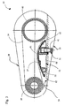
- a power transmission device (30) comprises a chain (36) or belt (not shown) operating between two sprockets (39) and (40).
- a case (38) preferably encloses the device and also acts as an abutment (33) for a piston (31), which is preferably spring-loaded.
- the chain sliding face (37) of a tensioner arm (32) mounted on a pivot (35) presses against the chain (36) to maintain tension.
- the tensioner arm (32) has a first side (60) and a second side (61) spaced from the first side.
- a first end (62) is disposed between the first (60) and second (61) sides.
- a second end (63) is disposed between the first (60) and second (61) sides, and spaced from the first end (62).
- the first (62) and second (63) ends join the first and second sides.
- the second side (61) provides the chain sliding face (37) which is in contact with the chain (36) to be tensioned.
- the second side (61) is arcuately shaped to provide a suitable chain travel surface.
- the second side (61) can have any suitable shape as dictated by manufacturing and consumer preference concerns.
- the tensioner arm (32) may be made from any material that meets all structural, environmental, wear and durability criteria. Materials such as steel, aluminum and plastics are preferably used as well as composites such as glass filled nylon.
- the chain sliding face (37) of a tensioner arm (32) may be made from any durable wear resistant material.
- a synthetic material such as nylon, which has high wearability and durability characteristics can be used.
- Nylon 6/6 is one commercially available material that may be used.
- the chain sliding face may be made of PEEK (polyetheretherketone), which also has high wearability and durability characteristics.
- PEEK polyetheretherketone
- the hydraulic tensioner (41) includes the piston (31), which applies force to the tensioner arm (32).
- the tensioner (41) is combined and incorporated into the tensioner arm (32) for improved packaging.
- the tensioning device extends from the tensioner arm (32).
- the button, or bottom end of the piston (47) contacts a stationary abutment (33). This contact forces the arm (32) away from the abutment (33) and into the chain path, causing tension.
- a non-return mechanism coupled to the piston (31) ensures that the piston (31) extends but does not retract more than an included backlash (55) amount.
- Non-return mechanisms take up worn chain slack to prevent sprocket tooth jump of the chain.
- the non-return mechanism is a ratcheting mechanism, but it will be understood by one skilled in the art that other non-return mechanisms are possible within the teachings of the invention, such as a cam, roller wedge or sprague mechanism, or rod-and-catch plate arrangement.
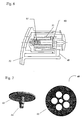
- the ratchet teeth (46) are located on the side of the piston (31), engaging ratchet teeth on a pawl (45) (see Fig. 4).
- a spring (44) is preferably located within the pawl (45) to maintain engagement of the pawl (45) to the ratchet teeth (46).
- the pawl (45) moves in and out along the axis of the spring (44).
- the pawl (45) motion is restricted to allow the piston (31) to extend but not retract except for the included backlash (55) amount.
- the pawl (45) prevents excessive chain motion due to peak chain loads or insufficient hydraulic pressure.
- a fluid inlet passageway (54) feeding an inlet check valve (52) is located in the submerged end of the piston (31) (see Fig. 5).
- a seal (53) ensures that there is little or no leakage.
- An outlet flow control, shown as check valve (50) and an outlet passageway (56) is located in the insert (42) at the other end of the piston-insert chamber. The outlet flow control prevents air entry when the piston extends, and permits controlled fluid outflow when the piston retracts.
- the inlet check valve (52) could alternatively be located in the insert (42) and the outlet flow control (50) could alternatively be located in the piston (31).
- a seal (64) ensures that there is little or no leakage.
- the included backlash amount in the non-return mechanism allows the tensioner to act as a self priming (purging) pump, without the need for an external fluid pressure supply. If the outlet passageway (56) is further restricted with an orifice (51) or tortuous path (58) or the like, the action of the hydraulic tensioner will be damped. In some applications, a tortuous path (58) alone can act as an outlet flow control.
- a retaining ring (43) is preferably located on a side of the insert (42) to contain the pawl (45) and a spring (44) when the piston (31) extends.
- the pawl (45) is preferably slidably connected to the tensioner arm and contained by the retaining ring (43).
- the pawl (45) is guided in a channel, which is preferably U-shaped. The pawl (45) slides up and down in the channel.
- the inlet check valve is an umbrella check valve (60).
- the umbrella check valve (60) includes a skirt (63), a stem (64), and a seat (65).
- the outlet flow control is preferably a pressure relief valve (61).
- the pressure relief valve (61) allows fluid to exit the piston (31) when the pressure in the piston (31) is high, thus allowing the piston to retract in response to rapid increases in chain tension.
- the inlet check valve and the outlet flow control are both ball check valves (66).
Claims (17)
- Hydraulischer Kettenspanner zum Aufbringen von Spannung auf eine Kette, mit:a) einer Kolbenanordnung miti) einem Kolben (31) mit einem hohlen Innenraum und einer Kolbenbohrung (42), die den Kolben (31) umgibt und eine Kammer mit diesem einschließt;ii) einem Einlassregulierventil (52) zum Steuern des Eintritts von Flüssigkeit in die Kammer, undb) einem mit dem Kolben (31) verbundenen Rücklaufsperrmechanismus (44 - 46), um das Ausfahren des Kolbens zu ermöglichen,dadurch gekennzeichnet, dass
das Einlassregulierventil (52) derart angeordnet ist, dass das Einlassregulierventil (52) unter dem Flüssigkeitsspiegel (34) liegt und den Strom der Flüssigkeit in die Kammer ermöglicht, wenn ein Ende der Kolbenanordnung in die Flüssigkeit eingetaucht ist;
der Rücklaufsperrmechanismus (44 - 46) das Einziehen des Kolbens um höchstens einen einbegriffenen Spielbetrag (55) ermöglichen kann;
die Kolbenanordnung des Weiteren ein Auslassregulierventil (50) umfasst, damit keine Luft eintreten kann, wenn der Kolben ausfährt, und ein gesteuerter Ausfluss ermöglicht wird, wenn der Kolben einfährt, und das an dem Ende der Kolbenanordnung angeordnet ist, die dem Einlassregulierventil (52) gegenüber liegt; und
der Spanner als selbstansaugende Pumpe wirkt, wodurch die durch den einbegriffenen Spielbetrag (55) ermöglichte Kolbenbewegung in Kombination mit dem Einlassregulierventil (52) und dem Auslassregulierventil (50) ermöglicht, dass der Spanner Flüssigkeit zum Füllen der Kammer in die Kammer saugt, ohne dass Flüssigkeit aus einer unter Druck stehenden äußeren Quelle zugeführt wird. - Spanner nach Anspruch 1, wobei der Rücklaufsperrmechanismus folgendes umfasst:a) eine Vielzahl von Klinkenradzähnen (46), die entlang einer Länge des Kolbens (31) ausgebildet sind, undb) eine angrenzend an den Kolben (31) angeordnete Klinke (45), wobei die Klinke (45) eine Vielzahl von Klinkenradzähnen umfasst, die mit den Klinkenradzähnen (46) an dem Kolben in Eingriff kommen.
- Spanner nach Anspruch 1 oder 2, des Weiteren mit einem Einlassweg (54) von dem Innenraum zu dem Außenraum des Kolbens (31), wobei der Einlassweg (54) mit dem Einlassregulierventil verbunden ist.
- Spanner nach einem der Ansprüche 1 bis 3, des Weiteren mit einem Auslassweg (56) von dem Innenraum zu dem Außenraum des Kolbens (31), wobei der Auslassweg mit dem Auslassregulierventil verbunden ist.
- Spanner nach Anspruch 4, wobei der Auslassweg (56) derart geformt ist, dass er auf den hydraulischen Spanner ein Dämpfung ausübt.
- Spanner nach Anspruch 4 oder 5, des Weiteren mit einer Öffnung (51), die den Auslassweg einengt.
- Spanner nach einem der Ansprüche 4 bis 6, des Weiteren mit einem gewundenen Weg (58), der den Auslassweg einengt.
- Spanner nach einem der Ansprüche 1 bis 7, wobei das Auslassregulierventil ein Kugelrückschlagventil (66) umfasst.
- Spanner nach einem der vorhergehenden Ansprüche, des Weiteren mit einem Spannerarm (32) mit einer Kettenseite (37) zum Kontakt mit der zu spannenden Kette (36), wobei mindestens ein anderer Teil des Spanners als der Spannerarm (32) selbst in dem Spannerarm (32) angeordnet ist.
- Spanner nach Anspruch 9, des Weiteren mit einem ortsfesten Widerlager (33), das derart mit einem ausfahrbaren Ende des Kolbens (31) in Kontakt kommt, dass der Spannerarm (32) von dem ortsfesten Widerlager (33) weg und in einen Weg der Kette (36) geschoben wird.
- Spanner nach einem der vorhergehenden Ansprüche, wobei das Einlassregulierventil (52) in dem Kolben (31) angeordnet ist und das Auslassregulierventil (50) in der Kolbenbohrung (42) angeordnet ist.
- Spanner nach einem der Ansprüche 1 bis 10, wobei wobei das Einlassregulierventil (52) in der Kolbenbohrung (42) angeordnet ist und das Auslassregulierventil (50) in dem Kolben (31) angeordnet ist.
- Spanner nach einem der vorhergehenden Ansprüche, wobei das Einlassregulierventil (52) ein Tellerrückschlagventil (60) ist.
- Spanner nach einem der vorhergehenden Ansprüche, wobei das Einlassregulierventil (52) ein Kugelrückschlagventil (66) ist.
- Spanner nach einem der vorhergehenden Ansprüche, wobei das Einlassregulierventil (52) unter dem Flüssigkeitsspiegel (34) liegt, wenn das Ende der Kolbenanordnung in Flüssigkeit eingetaucht ist.
- Spanner nach Anspruch 3, wobei der Spanner derart angebracht ist, dass der Einlassweg (54) unter dem Flüssigkeitsspiegel liegt, wenn das Ende der Kolbenanordnung in Flüssigkeit eingetaucht ist.
- Verfahren zum Aufbringen von Spannung auf eine Kette, mit den folgenden Schritten:a) Bereitstellen eines Spanners miti) einer Kolbenanordnung mit:A) einem Kolben (31) mit einem hohlen Innenraum und einer Kolbenbohrung (42), die den Kolben (31);B) einem Einlassregulierventil (52) zum Steuern des Eintritts von Flüssigkeit in die Kammer, das derart angeordnet ist, dass das Einlassregulierventil einen Flüssigkeitsstrom in den hohlen Innenraum ermöglicht, wenn ein Ende der Kolbenanordnung in die Flüssigkeit eingetaucht ist; undii) einem Rücklaufsperrmechanismus, der derart mit dem Kolben verbunden ist, dass der Kolben (31) ausfahrbar ist,dadurch gekennzeichnet, dass
die Kolbenanordnung des Weiteren ein Auslassregulierventil (50) umfasst, damit keine Luft eintreten kann, wenn der Kolben ausfährt, und ein gesteuertes Überlaufen der Flüssigkeit ermöglicht wird, wenn der Kolben einfährt, und das an dem Ende der Kolbenanordnung angeordnet ist, das dem Einlassregulierventil (52) gegenüber liegt; und der Rücklaufsperrmechanismus das Einziehen des Kolbens (31) um höchstens einen einbegriffenen Spielbetrag ermöglicht;b) Eintauchen eines Einlassendes des Spanners in eine Fluidversorgung derart, dass das Einlassregulierventil (52) unter dem Spiegel der Fluidversorgung liegt;c) Selbstansaugen des Spanners, wobei der Spanner auf Grund der Kolbenbewegung innerhalb des einbegriffenen Spielbetrags und auf Grund der Wirkung des Einlassregulierventils und des Auslassregulierventils die Fluidversorgung in den Spanner hebt, um einen Innenraum des Spanners zu füllen.
Applications Claiming Priority (2)
| Application Number | Priority Date | Filing Date | Title |
|---|---|---|---|
| US264809 | 2002-10-04 | ||
| US10/264,809 US6945889B2 (en) | 2002-10-04 | 2002-10-04 | Hydraulic chain tensioner |
Publications (2)
| Publication Number | Publication Date |
|---|---|
| EP1406029A1 EP1406029A1 (de) | 2004-04-07 |
| EP1406029B1 true EP1406029B1 (de) | 2006-09-27 |
Family
ID=31993588
Family Applications (1)
| Application Number | Title | Priority Date | Filing Date |
|---|---|---|---|
| EP03255390A Expired - Lifetime EP1406029B1 (de) | 2002-10-04 | 2003-08-29 | Hydraulischer Kettenspanner |
Country Status (6)
| Country | Link |
|---|---|
| US (1) | US6945889B2 (de) |
| EP (1) | EP1406029B1 (de) |
| JP (1) | JP2004125170A (de) |
| KR (1) | KR20040031609A (de) |
| CN (1) | CN1497200A (de) |
| DE (1) | DE60308616T2 (de) |
Families Citing this family (31)
| Publication number | Priority date | Publication date | Assignee | Title |
|---|---|---|---|---|
| US6852049B2 (en) * | 2003-01-24 | 2005-02-08 | Borgwarner Inc. | Ratcheting hydraulic chain tensioner with rotational reset and locking means |
| US20050266946A1 (en) * | 2003-04-25 | 2005-12-01 | Borgwarner Inc. | Two-shot unified chain tensioner arm or guide |
| US6939259B2 (en) * | 2003-04-25 | 2005-09-06 | Borgwarner Inc. | Two-shot unified chain tensioner arm or guide |
| US7537533B2 (en) * | 2003-10-15 | 2009-05-26 | Borgwarner Inc. | Chain tensioning device linking two strands of a chain drive |
| EP1647738B1 (de) * | 2004-10-15 | 2007-07-04 | Morse Tec Europe S.R.L. | Einrichtung zur Führung der Steuerkette einer Brennkraftmaschine, insbesondere einer Brennkraftmaschine mit V-Zylinderanordnung |
| JP3962052B2 (ja) * | 2004-11-02 | 2007-08-22 | 株式会社椿本チエイン | 油圧式テンショナ |
| US20060293133A1 (en) * | 2005-06-28 | 2006-12-28 | Borgwarner Inc. | Dual pivoting pawl tensioner |
| DE202006012966U1 (de) * | 2006-08-23 | 2007-12-27 | JOH. WINKLHOFER & SÖHNE GMBH & Co. KG | Spannschiene für einen Kettentrieb mit einem überbrückenden Führungskanalabschnitt als Aufdrückbereich |
| EP2174039B1 (de) * | 2007-07-23 | 2012-08-22 | BorgWarner Inc. | Modularer hydraulischer spanner mit sperrklinke |
| JP5424446B2 (ja) * | 2008-06-26 | 2014-02-26 | ボーグワーナー インコーポレーテッド | テンショニング装置 |
| DE102009021468A1 (de) * | 2008-07-23 | 2010-01-28 | Schaeffler Kg | Spanner mit Gelenk für Steuerkettensysteme |
| US8992358B2 (en) * | 2009-02-27 | 2015-03-31 | Borgwarner Inc. | Automotive timing chain system component and method thereof |
| US8523720B2 (en) * | 2009-07-02 | 2013-09-03 | Ford Global Technologies, Llc | Chain tensioner |
| DE102009032557A1 (de) * | 2009-07-10 | 2011-01-13 | Schaeffler Technologies Gmbh & Co. Kg | Spannvorrichtung für einen Zugmitteltrieb eines Kraftfahrzeuges |
| DE102010048832A1 (de) | 2010-10-18 | 2012-04-19 | Schaeffler Technologies Gmbh & Co. Kg | Spanneinrichtung mit externem Rastsystem |
| JP2012172810A (ja) * | 2011-02-23 | 2012-09-10 | Ntn Corp | チェーンガイド及びチェーンテンショナ装置 |
| JP5689335B2 (ja) * | 2011-03-01 | 2015-03-25 | 株式会社椿本チエイン | ラチェット式テンショナ |
| US9423009B2 (en) * | 2011-04-21 | 2016-08-23 | Ntn Corporation | Hydraulic auto-tensioner |
| JP6078533B2 (ja) * | 2011-06-03 | 2017-02-08 | ボーグワーナー インコーポレーテッド | テンショナおよびテンショナ用シュー |
| US9068530B2 (en) | 2013-03-15 | 2015-06-30 | Mahle International Gmbh | Connecting rod with lubrication passage |
| JP5952225B2 (ja) * | 2013-06-26 | 2016-07-13 | 株式会社椿本チエイン | チェーンテンショナ |
| US10208838B2 (en) * | 2014-10-29 | 2019-02-19 | Borgwarner Inc. | Vortex channel |
| US10400870B2 (en) * | 2014-10-29 | 2019-09-03 | Borgwarner Inc. | Valvular paths |
| US10156290B2 (en) * | 2015-02-06 | 2018-12-18 | FLIR Belgium BVBA | Belt drive tensioning system |
| JP6374840B2 (ja) * | 2015-08-03 | 2018-08-15 | 株式会社椿本チエイン | テンショナ |
| DE102016204519B4 (de) * | 2016-03-18 | 2018-02-08 | Magna powertrain gmbh & co kg | Nasslaufendes Zugmittelgetriebe |
| DE112018006596T5 (de) * | 2018-01-31 | 2020-11-12 | Borgwarner Inc. | Spannarm mit variabler kraft mit kappentellerfeder |
| GB2611911B (en) * | 2020-06-09 | 2023-12-27 | Ashlyn Antony | An apparatus for eliminating slack and vibrations in the chain of a chain drive |
| US11796040B2 (en) * | 2021-01-22 | 2023-10-24 | Borgwarner Inc. | Method(s) to apply tension to increase drivetrain jump torque capacity |
| CN114810965B (zh) * | 2022-05-09 | 2023-06-09 | 大庆丹诺石油科技开发有限公司 | 一种设有滚动轴承的抽油机皮带智能化调整装置 |
| US11828206B1 (en) * | 2022-11-14 | 2023-11-28 | Borgwarner Inc. | Hydraulic tensioner with external pin and ratchet mechanism |
Family Cites Families (31)
| Publication number | Priority date | Publication date | Assignee | Title |
|---|---|---|---|---|
| US4084606A (en) * | 1974-04-23 | 1978-04-18 | Baxter Travenol Laboratories, Inc. | Fluid transfer device |
| US3941149A (en) * | 1974-11-11 | 1976-03-02 | Baxter Laboratories, Inc. | Valve |
| DE3217632A1 (de) * | 1982-05-11 | 1983-11-17 | Porsche Ag | Hydraulischer kettenspanner |
| WO1988009867A1 (en) * | 1987-06-01 | 1988-12-15 | Eagle-Picher Industries, Inc. | Fuel injection system with umbrella check valve |
| US4921472A (en) * | 1989-06-12 | 1990-05-01 | Borg-Warner Automotive Transmission & Engine Components Corporation | Chain tensioner |
| US4997411A (en) * | 1990-01-29 | 1991-03-05 | Eaton Corporation | Cage and retainer combination for check valves and slack adjusters using same |
| JPH061890U (ja) | 1992-06-10 | 1994-01-14 | 株式会社椿本チエイン | 空気抜き機構付きオイル式テンショナ |
| US5507318A (en) * | 1994-10-04 | 1996-04-16 | Walbro Corporation | Umbrella check valves |
| DE19500940C1 (de) | 1995-01-14 | 1996-07-11 | Bosch Gmbh Robert | Vorrichtung zum Spannen von Ketten, insbesondere Steuerketten an Verbrennungsmotoren |
| US5720684A (en) * | 1995-09-06 | 1998-02-24 | Borg-Warner Automotive, Inc. | Hydraulic tensioner with internal pressure relief |
| JP2895786B2 (ja) | 1995-11-10 | 1999-05-24 | 株式会社椿本チエイン | 伝動チェーンのテンショナ装置 |
| US5647811A (en) * | 1996-01-18 | 1997-07-15 | Borg-Warner Automotive, Inc. | Chain tensioner with integral arm |
| US5776024A (en) * | 1996-04-03 | 1998-07-07 | Borg-Warner Automotive, Inc. | Tensioner with integral body and arm |
| DE19717360A1 (de) | 1996-04-29 | 1997-10-30 | Borg Warner Automotive | Hydraulischer Kettenspanner |
| CN1092304C (zh) * | 1996-08-02 | 2002-10-09 | Ina滚动轴承谢夫勒无限责任公司 | 张紧装置 |
| US5718650A (en) * | 1996-10-03 | 1998-02-17 | Borg-Warner Automotive, Inc. | Hydraulic tensioner with porous vent |
| EP0877180B1 (de) * | 1997-05-08 | 2003-01-22 | BorgWarner Inc. | Hydraulische Spannvorrichtung mit externem Klinkenwerk |
| US5967921A (en) * | 1997-10-09 | 1999-10-19 | Borg-Warner Automotive, Inc. | Hydraulic chain tensioner with molded plastic body |
| US5911641A (en) * | 1997-12-23 | 1999-06-15 | Eaton Corporation | Chain Tensioner and improved plunger retention thereof |
| US6120402A (en) * | 1998-09-21 | 2000-09-19 | Borgwarner Inc. | Hydraulic tensioner with external rack having backlash restriction |
| US6312351B1 (en) * | 1998-09-21 | 2001-11-06 | Borgwarner Inc. | Hydraulic tensioner with pivotal mount |
| US6244981B1 (en) * | 1998-09-21 | 2001-06-12 | Borgwarner Inc. | Hydraulic tensioner with pawl-style external rack |
| JP3243226B2 (ja) | 1999-02-18 | 2002-01-07 | 株式会社椿本チエイン | 油圧式テンショナ |
| JP3322396B2 (ja) * | 1999-06-30 | 2002-09-09 | 株式会社椿本チエイン | リリーフバルブ付油圧式テンショナ |
| JP2001021011A (ja) * | 1999-07-05 | 2001-01-26 | Borg Warner Automotive Kk | 液圧テンショナ |
| JP2001159454A (ja) * | 1999-11-30 | 2001-06-12 | Tsubakimoto Chain Co | プランジャストッパピン付きテンショナ |
| JP3226037B2 (ja) * | 2000-01-21 | 2001-11-05 | 株式会社椿本チエイン | プランジャの係止及び係止解除機構を備えたラチェット式テンショナ |
| JP3415536B2 (ja) * | 2000-01-21 | 2003-06-09 | 株式会社椿本チエイン | プランジャの係止保持機構、係止解除機構等を備えたラチェット式テンショナ |
| JP3432197B2 (ja) * | 2000-02-02 | 2003-08-04 | 株式会社椿本チエイン | バックラッシュを有するラチェット式テンショナ |
| JP3402587B2 (ja) * | 2000-07-03 | 2003-05-06 | 株式会社椿本チエイン | プランジャの係止解除機構を備えたラチェット式テンショナ |
| JP3356762B2 (ja) * | 2000-10-26 | 2002-12-16 | 株式会社椿本チエイン | リリーフバルブ機構付きテンショナ |
-
2002
- 2002-10-04 US US10/264,809 patent/US6945889B2/en not_active Expired - Fee Related
-
2003
- 2003-08-27 JP JP2003302566A patent/JP2004125170A/ja active Pending
- 2003-08-29 EP EP03255390A patent/EP1406029B1/de not_active Expired - Lifetime
- 2003-08-29 DE DE60308616T patent/DE60308616T2/de not_active Expired - Fee Related
- 2003-09-30 CN CNA031327346A patent/CN1497200A/zh active Pending
- 2003-10-02 KR KR1020030068571A patent/KR20040031609A/ko not_active Application Discontinuation
Also Published As
| Publication number | Publication date |
|---|---|
| US20040067806A1 (en) | 2004-04-08 |
| CN1497200A (zh) | 2004-05-19 |
| DE60308616D1 (de) | 2006-11-09 |
| EP1406029A1 (de) | 2004-04-07 |
| DE60308616T2 (de) | 2007-01-04 |
| KR20040031609A (ko) | 2004-04-13 |
| US6945889B2 (en) | 2005-09-20 |
| JP2004125170A (ja) | 2004-04-22 |
Similar Documents
| Publication | Publication Date | Title |
|---|---|---|
| EP1406029B1 (de) | Hydraulischer Kettenspanner | |
| US7641577B2 (en) | Mechanical chain tensioner with compliant blade spring | |
| US7628719B2 (en) | Mechanical strap tensioner for multi-strand tensioning | |
| US5277664A (en) | Hydraulic tensioner with a molded valve base and cap | |
| KR100232712B1 (ko) | 무단전동체의 텐셔너 | |
| EP0952375B1 (de) | Hydraulische Spannvorrichtung mit einem Überdruckventil. | |
| US6634973B1 (en) | Hydraulic tensioner with two spring biased pistons and cushioned pull-back rack | |
| EP0908646B1 (de) | Hydraulischer Kettenspanner mit einer tiefgezogenen, topfförmigen Zylinderbüchse | |
| US5346436A (en) | Air vent for hydraulic chain tensioner | |
| US7455606B2 (en) | Mechanical chain tensioner with a rotational ratcheting device | |
| EP1201964B1 (de) | Spannvorrichtung mit einem Überdruckventil | |
| EP1915549B1 (de) | Langer mechanischer spanner mit nachgiebiger blattfeder | |
| EP1984649B1 (de) | Spannarm zur kraftbegrenzung | |
| US20170356529A1 (en) | Variable force tensioning assembly | |
| US20080261737A1 (en) | Hydraulic tensioner | |
| US20110077114A1 (en) | Anchored mechanical strap tensioner for multi-strand tensioning | |
| US20100298077A1 (en) | Ratchet-type tensioner | |
| US20050197223A1 (en) | Hydraulic tensioner | |
| US20060293133A1 (en) | Dual pivoting pawl tensioner | |
| US5653653A (en) | Hydraulic tensioner with stop mechanism | |
| US7331891B2 (en) | Tensioner for a chain or belt | |
| US20090209376A1 (en) | Hydraulic tensioner | |
| US20090247335A1 (en) | Hydraulic tensioner | |
| EP1215415B1 (de) | Ketten- oder Riemenspanner | |
| EP1408254B1 (de) | Externer Schnappverschluss für eine kassettenartige, hydraulische Spannvorrichtung |
Legal Events
| Date | Code | Title | Description |
|---|---|---|---|
| PUAI | Public reference made under article 153(3) epc to a published international application that has entered the european phase |
Free format text: ORIGINAL CODE: 0009012 |
|
| AK | Designated contracting states |
Kind code of ref document: A1 Designated state(s): AT BE BG CH CY CZ DE DK EE ES FI FR GB GR HU IE IT LI LU MC NL PT RO SE SI SK TR |
|
| AX | Request for extension of the european patent |
Extension state: AL LT LV MK |
|
| 17P | Request for examination filed |
Effective date: 20040709 |
|
| 17Q | First examination report despatched |
Effective date: 20040909 |
|
| AKX | Designation fees paid |
Designated state(s): DE FR IT |
|
| RAP1 | Party data changed (applicant data changed or rights of an application transferred) |
Owner name: BORGWARNER INC. |
|
| GRAP | Despatch of communication of intention to grant a patent |
Free format text: ORIGINAL CODE: EPIDOSNIGR1 |
|
| RIN1 | Information on inventor provided before grant (corrected) |
Inventor name: MARKLEY, GEORGE L. Inventor name: HAESLOOP, J. CHRISTIAN |
|
| GRAS | Grant fee paid |
Free format text: ORIGINAL CODE: EPIDOSNIGR3 |
|
| GRAA | (expected) grant |
Free format text: ORIGINAL CODE: 0009210 |
|
| AK | Designated contracting states |
Kind code of ref document: B1 Designated state(s): DE FR IT |
|
| PG25 | Lapsed in a contracting state [announced via postgrant information from national office to epo] |
Ref country code: IT Free format text: LAPSE BECAUSE OF FAILURE TO SUBMIT A TRANSLATION OF THE DESCRIPTION OR TO PAY THE FEE WITHIN THE PRESCRIBED TIME-LIMIT;WARNING: LAPSES OF ITALIAN PATENTS WITH EFFECTIVE DATE BEFORE 2007 MAY HAVE OCCURRED AT ANY TIME BEFORE 2007. THE CORRECT EFFECTIVE DATE MAY BE DIFFERENT FROM THE ONE RECORDED. Effective date: 20060927 |
|
| REF | Corresponds to: |
Ref document number: 60308616 Country of ref document: DE Date of ref document: 20061109 Kind code of ref document: P |
|
| ET | Fr: translation filed | ||
| PLBE | No opposition filed within time limit |
Free format text: ORIGINAL CODE: 0009261 |
|
| STAA | Information on the status of an ep patent application or granted ep patent |
Free format text: STATUS: NO OPPOSITION FILED WITHIN TIME LIMIT |
|
| 26N | No opposition filed |
Effective date: 20070628 |
|
| PGFP | Annual fee paid to national office [announced via postgrant information from national office to epo] |
Ref country code: DE Payment date: 20080829 Year of fee payment: 6 |
|
| PGFP | Annual fee paid to national office [announced via postgrant information from national office to epo] |
Ref country code: FR Payment date: 20080807 Year of fee payment: 6 |
|
| REG | Reference to a national code |
Ref country code: FR Ref legal event code: ST Effective date: 20100430 |
|
| PG25 | Lapsed in a contracting state [announced via postgrant information from national office to epo] |
Ref country code: DE Free format text: LAPSE BECAUSE OF NON-PAYMENT OF DUE FEES Effective date: 20100302 Ref country code: FR Free format text: LAPSE BECAUSE OF NON-PAYMENT OF DUE FEES Effective date: 20090831 |