EP1406029B1 - Hydraulic chain tensioner - Google Patents
Hydraulic chain tensioner Download PDFInfo
- Publication number
- EP1406029B1 EP1406029B1 EP03255390A EP03255390A EP1406029B1 EP 1406029 B1 EP1406029 B1 EP 1406029B1 EP 03255390 A EP03255390 A EP 03255390A EP 03255390 A EP03255390 A EP 03255390A EP 1406029 B1 EP1406029 B1 EP 1406029B1
- Authority
- EP
- European Patent Office
- Prior art keywords
- piston
- check valve
- tensioner
- fluid
- inlet check
- Prior art date
- Legal status (The legal status is an assumption and is not a legal conclusion. Google has not performed a legal analysis and makes no representation as to the accuracy of the status listed.)
- Expired - Lifetime
Links
Images


Classifications
-
- F—MECHANICAL ENGINEERING; LIGHTING; HEATING; WEAPONS; BLASTING
- F16—ENGINEERING ELEMENTS AND UNITS; GENERAL MEASURES FOR PRODUCING AND MAINTAINING EFFECTIVE FUNCTIONING OF MACHINES OR INSTALLATIONS; THERMAL INSULATION IN GENERAL
- F16H—GEARING
- F16H7/00—Gearings for conveying rotary motion by endless flexible members
- F16H7/08—Means for varying tension of belts, ropes, or chains
- F16H7/0848—Means for varying tension of belts, ropes, or chains with means for impeding reverse motion
-
- F—MECHANICAL ENGINEERING; LIGHTING; HEATING; WEAPONS; BLASTING
- F16—ENGINEERING ELEMENTS AND UNITS; GENERAL MEASURES FOR PRODUCING AND MAINTAINING EFFECTIVE FUNCTIONING OF MACHINES OR INSTALLATIONS; THERMAL INSULATION IN GENERAL
- F16H—GEARING
- F16H7/00—Gearings for conveying rotary motion by endless flexible members
- F16H7/08—Means for varying tension of belts, ropes, or chains
- F16H2007/0802—Actuators for final output members
- F16H2007/0806—Compression coil springs
-
- F—MECHANICAL ENGINEERING; LIGHTING; HEATING; WEAPONS; BLASTING
- F16—ENGINEERING ELEMENTS AND UNITS; GENERAL MEASURES FOR PRODUCING AND MAINTAINING EFFECTIVE FUNCTIONING OF MACHINES OR INSTALLATIONS; THERMAL INSULATION IN GENERAL
- F16H—GEARING
- F16H7/00—Gearings for conveying rotary motion by endless flexible members
- F16H7/08—Means for varying tension of belts, ropes, or chains
- F16H2007/0802—Actuators for final output members
- F16H2007/0812—Fluid pressure
-
- F—MECHANICAL ENGINEERING; LIGHTING; HEATING; WEAPONS; BLASTING
- F16—ENGINEERING ELEMENTS AND UNITS; GENERAL MEASURES FOR PRODUCING AND MAINTAINING EFFECTIVE FUNCTIONING OF MACHINES OR INSTALLATIONS; THERMAL INSULATION IN GENERAL
- F16H—GEARING
- F16H7/00—Gearings for conveying rotary motion by endless flexible members
- F16H7/08—Means for varying tension of belts, ropes, or chains
- F16H7/0848—Means for varying tension of belts, ropes, or chains with means for impeding reverse motion
- F16H2007/0853—Ratchets
-
- F—MECHANICAL ENGINEERING; LIGHTING; HEATING; WEAPONS; BLASTING
- F16—ENGINEERING ELEMENTS AND UNITS; GENERAL MEASURES FOR PRODUCING AND MAINTAINING EFFECTIVE FUNCTIONING OF MACHINES OR INSTALLATIONS; THERMAL INSULATION IN GENERAL
- F16H—GEARING
- F16H7/00—Gearings for conveying rotary motion by endless flexible members
- F16H7/08—Means for varying tension of belts, ropes, or chains
- F16H7/0848—Means for varying tension of belts, ropes, or chains with means for impeding reverse motion
- F16H2007/0859—Check valves
-
- F—MECHANICAL ENGINEERING; LIGHTING; HEATING; WEAPONS; BLASTING
- F16—ENGINEERING ELEMENTS AND UNITS; GENERAL MEASURES FOR PRODUCING AND MAINTAINING EFFECTIVE FUNCTIONING OF MACHINES OR INSTALLATIONS; THERMAL INSULATION IN GENERAL
- F16H—GEARING
- F16H7/00—Gearings for conveying rotary motion by endless flexible members
- F16H7/08—Means for varying tension of belts, ropes, or chains
- F16H2007/0863—Finally actuated members, e.g. constructional details thereof
- F16H2007/0872—Sliding members
Description
- The present invention relates generally to tensioners used with chain drives in automotive timing and power transmission applications. In particular, the present invention is related to a hydraulic chain tensioner system, and to a method of applying tension to a chain according to the preamble of
claims - A tensioning device, such as a hydraulic tensioner, is used as a control device for a power transmission chain, or similar power transmission devices, as the chain travels between a plurality of sprockets. In this device, the chain transmits power from a driving shaft to a driven shaft, so that part of the chain is slack and part of the chain is tight. Generally, it is important to impart and maintain a certain degree of tension in the chain to prevent noise, slippage, or the unmeshing of teeth in the case of a toothed chain. Prevention of such slippage is particularly important in the case of a chain driven camshaft in an internal combustion engine because jumping of teeth will throw off the camshaft timing, possibly causing damage or rendering the engine inoperative.
- However, in the harsh environment of an internal combustion engine, various factors can cause fluctuations in the chain tension. For instance, wide variations in temperature and thermal expansion coefficients among the various parts of the engine can cause the chain tension to vary between excessively high or low levels. During prolonged use, wear to the components of the power transmission system can cause a decrease in chain tension. In addition, camshaft and crankshaft induced torsional vibrations cause considerable variations in chain tensions. Reverse rotation of an engine, occurring for example in stopping or in failed attempts at starting, can also cause fluctuations in chain tension. For these reasons, a mechanism is desired to remove excessive tensioning forces on the tight side of the chain and to ensure the necessary tension on the slack side of the chain.
- Hydraulic tensioners are a common method of maintaining proper chain tension. In general, these mechanisms employ a lever arm that pushes against the chain on the slack side of the power transmission system. This lever arm must push toward the chain, tightening the chain when the chain is slack, and must be very rigid when the chain tightens.
- To accomplish this result, a hydraulic tensioner typically comprises a rod or cylinder as a piston, which is biased in the direction of the chain by a tensioner spring. The piston is housed within a cylindrical housing, having an interior space which is open at the end facing the chain and closed at the other end. The interior space of the housing contains a pressure chamber in connection with a reservoir or exterior source of hydraulic fluid pressure. The pressure chamber is typically formed between the housing and the piston, and it expands or contracts when the piston moves within the housing.
- Typically, valves are employed to regulate the flow of fluid into and out of the pressure chamber. For instance, an inlet check valve typically includes a ball-check valve that opens to permit fluid flow in to the pressure chamber when the pressure inside the chamber has decreased as a result of outward movement of the piston. When the pressure in the pressure chamber is high, the inlet check valve closes, preventing fluid from exiting the pressure chamber. The closing of the inlet check valve prevents the piston chamber from contracting, which in turn prevents the piston from retracting, achieving a so-called "no-return" function.
- Many tensioners also employ a pressure relief mechanism that allows fluid to exit the pressure chamber when the pressure in the chamber is high, thus allowing the piston to retract in response to rapid increases in chain tension. In some tensioners, the pressure relief mechanism is a spring biased check valve. The check valve opens when the pressure exceeds a certain pressure point. Some tensioners may employ a valve which performs both the inlet check function as well as the pressure relief function.
- Other mechanisms employ a restricted path through which fluid may exit the fluid chamber, such that the volume of flow exiting the fluid chamber is minimal unless the pressure in the fluid chamber is great. For instance, a restricted path may be provided through the clearance between the piston and bore, through a vent tube in the protruding end of the piston, or through a vent member between the fluid chamber and the fluid reservoir.
- A hydraulic tensioner as used with a tensioner arm or shoe is shown in Simpson et al., U.S. Pat. No. 5,967,921, incorporated herein by reference. Hydraulic chain tensioners typically have a plunger slidably fitted into a chamber and biased outward by a spring to provide tension to the chain. A lever, arm or shoe is often used at the end of the plunger to assist in the tensioning of the chain. The hydraulic pressure from an external source, such as an oil pump or the like, flows into the chamber through passages formed in the housing. The plunger is moved outward against the arm by the combined efforts of the hydraulic pressure and the spring force.
- When the plunger tends to move in a reverse direction (inward) away from the chain, typically a check valve is provided to restrict the flow of fluid from the chamber. In such a fashion, the tensioner achieves a so-called no-return function, i.e., movements of the plunger are easy in one direction (outward) but difficult in the reverse direction.
- Another hydraulic tensioner is shown in the closest prior art document U.S. Pat. No. 6,383,103. This patent shows a hydraulic tensioner with a relief valve mechanism assembled in a plunger and held in fluid communication with a high-pressure oil chamber. The relief valve mechanism includes an orifice and a relief valve.
- Blade and block tensioners have been used in the past to apply tension to chains. A block tensioner (1) as known in the prior art is shown in Fig. 1. The tensioner (1) has a piston (2) located within a housing (5). The springs (3) are located in a fluid chamber (4) within the piston (2).
- An example of a blade tensioner is shown in Fig. 2. The conventional blade tensioner (10) includes a blade shoe (11) made of resin having a curved chain sliding face and numerous blade springs (21) preferably made of metallic material. The blade springs (21) are arranged in layers on the opposite side of the blade shoe (11) from the chain sliding face, and provide spring force to the blade shoe (11). The ends of each spring-shaped blade spring (21) are inserted in the indented portions (14) and (15) which are formed in the distal portion (12) and proximal portion (13) of the blade shoe (11), respectively.
- A bracket (17) is provided for mounting the blade tensioner (10) in an engine. Holes (18) and (19) are formed in the bracket (17), and mounting bolts are inserted into these holes (18) and (19). A sliding face (16) contacts the distal portion of the blade shoe (11) and permits sliding. The slide face (16) is formed on the distal portion of the bracket (17). A pin (20) supports the proximal portion (13) of the blade shoe (11) so that it may move in either direction. The pin (20) is secured in the center of the bracket (17).
- U.S. Patent No. 5,647,811, shows a chain tensioner with an integrated tensioner and arm. The hydraulic tensioner in that patent is pressure fed.
- Due to space restrictions, functionality or numerous other reasons, common tensioners such as the block type tensioners (Fig. 1) and blade type tensioners (Fig. 2) discussed above cannot be used in some applications. Therefore, there is a need in the art for an improved tensioner which can overcome the prior art shortcomings.
- The present invention provides a hydraulic tensioner for applying tension to a chain, comprising:
- a) a piston assembly comprising:
- i) a piston with a hollow interior, and a piston bore surrounding the piston and confining a chamber therewith;
- ii) an inlet check valve for controlling entry of fluid into the chamber; and
- b) a non-return mechanism coupled to the piston to allow extension of the piston characterized in that
the inlet check valve is located such that when an end of the piston assembly is submerged in fluid, the inlet check valve is located below the fluid level and permits flow of the fluid into the chamber;
the non-return mechanism is arranged to allow retraction of the piston by no more than an included backlash amount;
the piston assembly further comprises an outlet check valve for preventing air entry when the piston extends and permitting controlled fluid outflow when the piston retracts, located at an opposite end of the piston assembly from the inlet check valve; and - Advantageously the tensioner can tension a chain without any need for an external fluid pressure supply. An end of the piston assembly can be submerged in fluid. The inlet check valve, which controls entry of fluid into the piston, is preferably located below the fluid level.
The invention correspondingly provides a method of applying tension to a chain comprising the steps of: - a) providing a tensioner comprising:
- i) a piston assembly comprising:
- A) a piston with a hollow interior and a piston bore surrounding the piston:
- B) an inlet check valve for controlling an entry of fluid into the piston, located such that when an end of the piston assembly is submerged in fluid, the inlet check valve permits fluid flow into the hollow interior; and
- ii) a non-return mechanism coupled to the piston such that the piston is extendable
the piston assembly further comprising an outlet check valve for preventing air entry when the piston extends and permitting controlled fluid overflow when the piston retracts, located at an opposite end of the piston assembly from the inlet check valve; and the non-return mechanism allowing retraction of the piston by no more than an included backlash amount; - i) a piston assembly comprising:
- b) submerging an inlet end of the tensioner in a fluid supply such that an inlet check valve is under a level of the fluid supply;
- c) self-priming the tensioner, wherein the tensioner lifts the fluid supply into the tensioner due to piston motion within the included backlash amount and due to action of the inlet check valve and the outlet check valve, to fill an interior of the tensioner.
-
- Fig. 1 shows a block tensioner as known in the prior art.
- Fig. 2 shows a blade tensioner as known in the prior art.
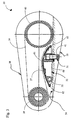
- Fig. 3 shows a hydraulic tensioner of the present invention.
- Fig. 4 shows a blown up view of the tensioner arm in Fig. 3.
- Fig. 5 shows another blown up view of the tensioner arm in Fig. 3.
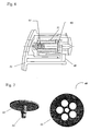
- Fig. 6 shows a preferred embodiment of the hydraulic tensioner of the present invention.
- Fig. 7 shows a blown up view of the umbrella check valve shown in Fig. 6.
- Fig. 8 shows another preferred embodiment of the hydraulic tensioner of the present invention.
- In some of the applications where the prior art tensioners of Fig. 1 and 2 could not be used, a tensioner arm incorporating a spring-loaded piston pushing against a stationary object would suffice. However, the limitation of a spring loaded piston is that the spring force to overcome peak chain loading and to maintain chain control causes excessive chain wear.
- Referring now to Figs. 3 through 5, a preferred embodiment of the present invention is shown. A power transmission device (30) comprises a chain (36) or belt (not shown) operating between two sprockets (39) and (40). A case (38) preferably encloses the device and also acts as an abutment (33) for a piston (31), which is preferably spring-loaded. The chain sliding face (37) of a tensioner arm (32) mounted on a pivot (35) presses against the chain (36) to maintain tension.
- The tensioner arm (32) has a first side (60) and a second side (61) spaced from the first side. A first end (62) is disposed between the first (60) and second (61) sides. A second end (63) is disposed between the first (60) and second (61) sides, and spaced from the first end (62). Preferably, the first (62) and second (63) ends join the first and second sides. The second side (61) provides the chain sliding face (37) which is in contact with the chain (36) to be tensioned. Preferably, the second side (61) is arcuately shaped to provide a suitable chain travel surface. Of course, it will be understood by one skilled in the art that the second side (61) can have any suitable shape as dictated by manufacturing and consumer preference concerns.
- The tensioner arm (32) may be made from any material that meets all structural, environmental, wear and durability criteria. Materials such as steel, aluminum and plastics are preferably used as well as composites such as glass filled nylon.
- The chain sliding face (37) of a tensioner arm (32) may be made from any durable wear resistant material. A synthetic material, such as nylon, which has high wearability and durability characteristics can be used. In particular, Nylon 6/6 is one commercially available material that may be used. Alternatively, the chain sliding face may be made of PEEK (polyetheretherketone), which also has high wearability and durability characteristics. One of ordinary skill in the art would be capable of selecting one of these or other numerous suitable materials.
- The hydraulic tensioner (41) includes the piston (31), which applies force to the tensioner arm (32). In a preferred embodiment, the tensioner (41) is combined and incorporated into the tensioner arm (32) for improved packaging. The tensioning device extends from the tensioner arm (32). The button, or bottom end of the piston (47) contacts a stationary abutment (33). This contact forces the arm (32) away from the abutment (33) and into the chain path, causing tension.
- A non-return mechanism coupled to the piston (31) ensures that the piston (31) extends but does not retract more than an included backlash (55) amount. Non-return mechanisms take up worn chain slack to prevent sprocket tooth jump of the chain. In a preferred embodiment, the non-return mechanism is a ratcheting mechanism, but it will be understood by one skilled in the art that other non-return mechanisms are possible within the teachings of the invention, such as a cam, roller wedge or sprague mechanism, or rod-and-catch plate arrangement. The ratchet teeth (46) are located on the side of the piston (31), engaging ratchet teeth on a pawl (45) (see Fig. 4). A spring (44) is preferably located within the pawl (45) to maintain engagement of the pawl (45) to the ratchet teeth (46). The pawl (45) moves in and out along the axis of the spring (44). The pawl (45) motion is restricted to allow the piston (31) to extend but not retract except for the included backlash (55) amount. The pawl (45) prevents excessive chain motion due to peak chain loads or insufficient hydraulic pressure.
- Applying the above concept in an application using oil bath chain lubrication allows an end of the tensioning piston (31) to be submerged in the fluid bath. As shown in the figures, the fluid level (34) is above the extended portion of the piston (31).
- A fluid inlet passageway (54) feeding an inlet check valve (52) is located in the submerged end of the piston (31) (see Fig. 5). A seal (53) ensures that there is little or no leakage. An outlet flow control, shown as check valve (50) and an outlet passageway (56) is located in the insert (42) at the other end of the piston-insert chamber. The outlet flow control prevents air entry when the piston extends, and permits controlled fluid outflow when the piston retracts. As long as the inlet check valve (52) is submerged in fluid, the inlet check valve (52) could alternatively be located in the insert (42) and the outlet flow control (50) could alternatively be located in the piston (31). A seal (64) ensures that there is little or no leakage.
- The included backlash amount in the non-return mechanism, combined with the inlet check valve and outlet flow control in the piston, allows the tensioner to act as a self priming (purging) pump, without the need for an external fluid pressure supply. If the outlet passageway (56) is further restricted with an orifice (51) or tortuous path (58) or the like, the action of the hydraulic tensioner will be damped. In some applications, a tortuous path (58) alone can act as an outlet flow control.
- A retaining ring (43) is preferably located on a side of the insert (42) to contain the pawl (45) and a spring (44) when the piston (31) extends. The pawl (45) is preferably slidably connected to the tensioner arm and contained by the retaining ring (43). In a preferred embodiment, the pawl (45) is guided in a channel, which is preferably U-shaped. The pawl (45) slides up and down in the channel.
- In one example of the invention, shown in Figs. 6 and 7, the inlet check valve is an umbrella check valve (60). The umbrella check valve (60) includes a skirt (63), a stem (64), and a seat (65). In this example, the outlet flow control is preferably a pressure relief valve (61). The pressure relief valve (61) allows fluid to exit the piston (31) when the pressure in the piston (31) is high, thus allowing the piston to retract in response to rapid increases in chain tension. In another example, shown in Fig. 8, the inlet check valve and the outlet flow control are both ball check valves (66).
- Accordingly, it is to be understood that the embodiments of the invention herein described are merely illustrative of the application of the principles of the invention. Reference herein to details of the illustrated embodiments is not intended to limit the scope of the claims, which themselves recite those features regarded as essential to the invention.
Claims (17)
- A hydraulic tensioner for applying tension to a chain, comprising:a) a piston assembly comprising:i) a piston (31) with a hollow interior, and a piston bore (42) surrounding the piston (31) and confining a chamber therewith;ii) an inlet check valve (52) for controlling entry of fluid into the chamber; andb) a non-return mechanism (44-46) coupled to the piston (31) to allow extension of the piston (31)
characterized in that
the inlet check valve (52) is located such that when an end of the piston assembly is submerged in fluid, the inlet check valve (52) is located below the fluid level (34) and permits flow of the fluid into the chamber;
the non-return mechanism (44-46) is arranged to allow retraction of the piston by no more than an included backlash amount (55);
the piston assembly further comprises an outlet check valve (50) for preventing air entry when the piston extends and permitting controlled fluid outflow when the piston retracts, located at an opposite end of the piston assembly from the inlet check valve (52); and
the tensioner acts as a self-priming pump whereby the piston motion allowed by the included backlash amount (55) in combination with the inlet check valve and the outlet check valve, enables the tensioner to draw fluid into the chamber for filling the chamber without fluid being supplied from an external source under pressure. - A tensioner according to claim 1, wherein the non-return mechanism comprises:a) a plurality of ratchet teeth (46) formed along a length of the piston (31); andb) a pawl (45) disposed adjacent to the piston (31), wherein the pawl (45) comprises a plurality of ratchet teeth which engage the ratchet teeth (46) on the piston (31).
- A tensioner according to claim 1 or 2, further comprising an inlet passageway (54) from the interior to the exterior of the piston (31), wherein the inlet passageway (54) is connected to the inlet check valve.
- A tensioner according to any one of claims 1 to 3, further comprising an outlet passageway (56) from the interior to the exterior of the piston (31), wherein the outlet passageway is connected to the outlet check valve.
- A tensioner according to claim 4, wherein the outlet passageway (56) is shaped to provide the hydraulic tensioner with damping.
- A tensioner according to claim 4 or 5, further comprising an orifice (51) restricting the outlet passageway.
- A tensioner according to any one of claims 4 to 6, further comprising a tortuous path (58) restricting the outlet passageway.
- A tensioner according to any one of claims 1 to 7, wherein the outlet check valve comprises a ball check valve (66).
- A tensioner according to any one of the preceding claims, further comprising a tensioner arm (32) having a chain side (37) for contact with the chain (36) to be tensioned, wherein at least part of the tensioner other than the tensioner arm (32) itself is disposed in the tensioner arm(32).
- A tensioner according to claim 9, further comprising a stationary abutment (33) which contacts an extendable end of the piston (31) such that the tensioner arm (32) is pushed away from the stationary abutment (33) and into a path of the chain (36).
- A tensioner according to any one of the preceding claims, wherein the inlet check valve (52) is located in the piston (31) and the outlet check valve (50) is located in the piston bore (42).
- A tensioner according to any one of claims 1 to 10, wherein the inlet check valve (52) is located in the piston bore (42) and the outlet check valve (50) is located in the piston (31).
- A tensioner according to any one of the preceding claims, wherein the inlet check valve (52) is an umbrella check valve (60).
- A tensioner according to any one of the preceding claims, wherein the inlet check valve (52) is a ball check valve (66).
- A tensioner according to any one of the preceding claims, wherein, when the end of the piston assembly is submerged in fluid, the inlet check valve (52) is located below the fluid level.
- A tensioner according to claim 3, wherein the tensioner is mounted such that the inlet passageway (54) is located below the fluid level when the end of the piston assembly is submerged in fluid.
- A method of applying tension to a chain comprising the steps of:a) providing a tensioner comprising:i) a piston assembly comprising:A) a piston (31) with a hollow interior and a piston bore (42) surrounding the piston (31);B) an inlet check valve (52) for controlling an entry of fluid into the piston, located such that when an end of the piston assembly is submerged in fluid, the inlet check valve permits fluid flow into the hollow interior; andii) a non-return mechanism coupled to the piston (31) such that the piston (31) is extendablecharacterized by
the piston assembly further comprising an outlet check valve (50) for preventing air entry when the piston extends and permitting controlled fluid overflow when the piston retracts, located at an opposite end of the piston assembly from the inlet check valve (52); and the non-return mechanism allowing retraction of the piston (31) by no more than an included backlash amount;b) submerging an inlet end of the tensioner in a fluid supply such that the inlet check valve (52) is under a level of the fluid supply;c) self-priming the tensioner, wherein the tensioner lifts the fluid supply into the tensioner due to piston motion within the included backlash amount and due to action of the inlet check valve and the outlet check valve, to fill an interior of the tensioner.
Applications Claiming Priority (2)
| Application Number | Priority Date | Filing Date | Title |
|---|---|---|---|
| US10/264,809 US6945889B2 (en) | 2002-10-04 | 2002-10-04 | Hydraulic chain tensioner |
| US264809 | 2002-10-04 |
Publications (2)
| Publication Number | Publication Date |
|---|---|
| EP1406029A1 EP1406029A1 (en) | 2004-04-07 |
| EP1406029B1 true EP1406029B1 (en) | 2006-09-27 |
Family
ID=31993588
Family Applications (1)
| Application Number | Title | Priority Date | Filing Date |
|---|---|---|---|
| EP03255390A Expired - Lifetime EP1406029B1 (en) | 2002-10-04 | 2003-08-29 | Hydraulic chain tensioner |
Country Status (6)
| Country | Link |
|---|---|
| US (1) | US6945889B2 (en) |
| EP (1) | EP1406029B1 (en) |
| JP (1) | JP2004125170A (en) |
| KR (1) | KR20040031609A (en) |
| CN (1) | CN1497200A (en) |
| DE (1) | DE60308616T2 (en) |
Families Citing this family (31)
| Publication number | Priority date | Publication date | Assignee | Title |
|---|---|---|---|---|
| US6852049B2 (en) * | 2003-01-24 | 2005-02-08 | Borgwarner Inc. | Ratcheting hydraulic chain tensioner with rotational reset and locking means |
| US20050266946A1 (en) * | 2003-04-25 | 2005-12-01 | Borgwarner Inc. | Two-shot unified chain tensioner arm or guide |
| US6939259B2 (en) * | 2003-04-25 | 2005-09-06 | Borgwarner Inc. | Two-shot unified chain tensioner arm or guide |
| US7537533B2 (en) * | 2003-10-15 | 2009-05-26 | Borgwarner Inc. | Chain tensioning device linking two strands of a chain drive |
| EP1647738B1 (en) * | 2004-10-15 | 2007-07-04 | Morse Tec Europe S.R.L. | Guide device for the chain of the timing system of an internal combustion engine, in particular of a V-engine |
| JP3962052B2 (en) * | 2004-11-02 | 2007-08-22 | 株式会社椿本チエイン | Hydraulic tensioner |
| US20060293133A1 (en) * | 2005-06-28 | 2006-12-28 | Borgwarner Inc. | Dual pivoting pawl tensioner |
| DE202006012966U1 (en) * | 2006-08-23 | 2007-12-27 | JOH. WINKLHOFER & SÖHNE GMBH & Co. KG | Clamping rail for a chain drive with a bridging guide channel section as pressing area |
| EP2174039B1 (en) * | 2007-07-23 | 2012-08-22 | BorgWarner Inc. | Modular hydraulic tensioner with ratchet |
| JP5424446B2 (en) * | 2008-06-26 | 2014-02-26 | ボーグワーナー インコーポレーテッド | Tensioning device |
| DE102009021468A1 (en) * | 2008-07-23 | 2010-01-28 | Schaeffler Kg | Tensioner with joint for timing chain systems |
| US8992358B2 (en) * | 2009-02-27 | 2015-03-31 | Borgwarner Inc. | Automotive timing chain system component and method thereof |
| US8523720B2 (en) * | 2009-07-02 | 2013-09-03 | Ford Global Technologies, Llc | Chain tensioner |
| DE102009032557A1 (en) * | 2009-07-10 | 2011-01-13 | Schaeffler Technologies Gmbh & Co. Kg | Clamping device for tractive drive of internal-combustion engine of motor vehicle, has clamping arm and counter bearing that are formed from sliding bearing material within region of conical bearing surfaces |
| DE102010048832A1 (en) | 2010-10-18 | 2012-04-19 | Schaeffler Technologies Gmbh & Co. Kg | Tensioning arrangement for traction drive of combustion engine, has tensioning unit exerting clamping force on rail and comprising external detent system with detent bodies that are integrally formed with rail |
| JP2012172810A (en) * | 2011-02-23 | 2012-09-10 | Ntn Corp | Chain guide and chain tensioner device |
| JP5689335B2 (en) * | 2011-03-01 | 2015-03-25 | 株式会社椿本チエイン | Ratchet tensioner |
| WO2012144402A1 (en) * | 2011-04-21 | 2012-10-26 | Ntn株式会社 | Hydraulic automatic tensioner |
| CN103597246B (en) * | 2011-06-03 | 2016-08-31 | 博格华纳公司 | Stretcher and for its tensioning boots |
| US9068530B2 (en) | 2013-03-15 | 2015-06-30 | Mahle International Gmbh | Connecting rod with lubrication passage |
| JP5952225B2 (en) * | 2013-06-26 | 2016-07-13 | 株式会社椿本チエイン | Chain tensioner |
| KR20170078679A (en) * | 2014-10-29 | 2017-07-07 | 보르그워너 인코퍼레이티드 | Vortex channel |
| US10400870B2 (en) * | 2014-10-29 | 2019-09-03 | Borgwarner Inc. | Valvular paths |
| US10156290B2 (en) * | 2015-02-06 | 2018-12-18 | FLIR Belgium BVBA | Belt drive tensioning system |
| JP6374840B2 (en) * | 2015-08-03 | 2018-08-15 | 株式会社椿本チエイン | Tensioner |
| DE102016204519B4 (en) * | 2016-03-18 | 2018-02-08 | Magna powertrain gmbh & co kg | Wet running traction mechanism |
| JP7053852B2 (en) * | 2018-01-31 | 2022-04-12 | ボーグワーナー インコーポレーテッド | Variable force tensioner arm with cap disc spring |
| EP4162174A4 (en) * | 2020-06-09 | 2024-04-03 | Antony Ashlyn | An apparatus for eliminating slack and vibrations in the chain of a chain drive |
| US11796040B2 (en) * | 2021-01-22 | 2023-10-24 | Borgwarner Inc. | Method(s) to apply tension to increase drivetrain jump torque capacity |
| CN114810965B (en) * | 2022-05-09 | 2023-06-09 | 大庆丹诺石油科技开发有限公司 | Intelligent adjusting device of beam-pumping unit belt with antifriction bearing |
| US11828206B1 (en) * | 2022-11-14 | 2023-11-28 | Borgwarner Inc. | Hydraulic tensioner with external pin and ratchet mechanism |
Family Cites Families (31)
| Publication number | Priority date | Publication date | Assignee | Title |
|---|---|---|---|---|
| US4084606A (en) * | 1974-04-23 | 1978-04-18 | Baxter Travenol Laboratories, Inc. | Fluid transfer device |
| US3941149A (en) * | 1974-11-11 | 1976-03-02 | Baxter Laboratories, Inc. | Valve |
| DE3217632A1 (en) * | 1982-05-11 | 1983-11-17 | Porsche Ag | HYDRAULIC CHAIN TENSIONER |
| WO1988009867A1 (en) * | 1987-06-01 | 1988-12-15 | Eagle-Picher Industries, Inc. | Fuel injection system with umbrella check valve |
| US4921472A (en) * | 1989-06-12 | 1990-05-01 | Borg-Warner Automotive Transmission & Engine Components Corporation | Chain tensioner |
| US4997411A (en) * | 1990-01-29 | 1991-03-05 | Eaton Corporation | Cage and retainer combination for check valves and slack adjusters using same |
| JPH061890U (en) | 1992-06-10 | 1994-01-14 | 株式会社椿本チエイン | Oil tensioner with air venting mechanism |
| US5507318A (en) * | 1994-10-04 | 1996-04-16 | Walbro Corporation | Umbrella check valves |
| DE19500940C1 (en) | 1995-01-14 | 1996-07-11 | Bosch Gmbh Robert | Tightener for chains, esp. control chains of IC engines |
| US5720684A (en) * | 1995-09-06 | 1998-02-24 | Borg-Warner Automotive, Inc. | Hydraulic tensioner with internal pressure relief |
| JP2895786B2 (en) * | 1995-11-10 | 1999-05-24 | 株式会社椿本チエイン | Transmission chain tensioner device |
| US5647811A (en) * | 1996-01-18 | 1997-07-15 | Borg-Warner Automotive, Inc. | Chain tensioner with integral arm |
| US5776024A (en) * | 1996-04-03 | 1998-07-07 | Borg-Warner Automotive, Inc. | Tensioner with integral body and arm |
| DE19717360A1 (en) | 1996-04-29 | 1997-10-30 | Borg Warner Automotive | Cam chain tensioner for motor vehicle four=stroke IC-engine |
| WO1998005883A1 (en) * | 1996-08-02 | 1998-02-12 | INA Wälzlager Schaeffler oHG | Tensioning device |
| US5718650A (en) * | 1996-10-03 | 1998-02-17 | Borg-Warner Automotive, Inc. | Hydraulic tensioner with porous vent |
| EP0877180B1 (en) * | 1997-05-08 | 2003-01-22 | BorgWarner Inc. | Hydraulic tensioner with external rack and ratchet |
| US5967921A (en) * | 1997-10-09 | 1999-10-19 | Borg-Warner Automotive, Inc. | Hydraulic chain tensioner with molded plastic body |
| US5911641A (en) * | 1997-12-23 | 1999-06-15 | Eaton Corporation | Chain Tensioner and improved plunger retention thereof |
| US6312351B1 (en) * | 1998-09-21 | 2001-11-06 | Borgwarner Inc. | Hydraulic tensioner with pivotal mount |
| US6244981B1 (en) * | 1998-09-21 | 2001-06-12 | Borgwarner Inc. | Hydraulic tensioner with pawl-style external rack |
| US6120402A (en) * | 1998-09-21 | 2000-09-19 | Borgwarner Inc. | Hydraulic tensioner with external rack having backlash restriction |
| JP3243226B2 (en) * | 1999-02-18 | 2002-01-07 | 株式会社椿本チエイン | Hydraulic tensioner |
| JP3322396B2 (en) * | 1999-06-30 | 2002-09-09 | 株式会社椿本チエイン | Hydraulic tensioner with relief valve |
| JP2001021011A (en) * | 1999-07-05 | 2001-01-26 | Borg Warner Automotive Kk | Hydraulic tensioner |
| JP2001159454A (en) * | 1999-11-30 | 2001-06-12 | Tsubakimoto Chain Co | Tensioner with plunger stopper pin |
| JP3226037B2 (en) * | 2000-01-21 | 2001-11-05 | 株式会社椿本チエイン | Ratchet type tensioner with plunger locking and unlocking mechanism |
| JP3415536B2 (en) * | 2000-01-21 | 2003-06-09 | 株式会社椿本チエイン | Ratchet type tensioner equipped with a mechanism for retaining and releasing the plunger |
| JP3432197B2 (en) * | 2000-02-02 | 2003-08-04 | 株式会社椿本チエイン | Ratchet type tensioner with backlash |
| JP3402587B2 (en) * | 2000-07-03 | 2003-05-06 | 株式会社椿本チエイン | Ratchet tensioner with plunger unlocking mechanism |
| JP3356762B2 (en) * | 2000-10-26 | 2002-12-16 | 株式会社椿本チエイン | Tensioner with relief valve mechanism |
-
2002
- 2002-10-04 US US10/264,809 patent/US6945889B2/en not_active Expired - Fee Related
-
2003
- 2003-08-27 JP JP2003302566A patent/JP2004125170A/en active Pending
- 2003-08-29 DE DE60308616T patent/DE60308616T2/en not_active Expired - Fee Related
- 2003-08-29 EP EP03255390A patent/EP1406029B1/en not_active Expired - Lifetime
- 2003-09-30 CN CNA031327346A patent/CN1497200A/en active Pending
- 2003-10-02 KR KR1020030068571A patent/KR20040031609A/en not_active Application Discontinuation
Also Published As
| Publication number | Publication date |
|---|---|
| DE60308616T2 (en) | 2007-01-04 |
| EP1406029A1 (en) | 2004-04-07 |
| JP2004125170A (en) | 2004-04-22 |
| KR20040031609A (en) | 2004-04-13 |
| US20040067806A1 (en) | 2004-04-08 |
| DE60308616D1 (en) | 2006-11-09 |
| US6945889B2 (en) | 2005-09-20 |
| CN1497200A (en) | 2004-05-19 |
Similar Documents
| Publication | Publication Date | Title |
|---|---|---|
| EP1406029B1 (en) | Hydraulic chain tensioner | |
| US7641577B2 (en) | Mechanical chain tensioner with compliant blade spring | |
| US7628719B2 (en) | Mechanical strap tensioner for multi-strand tensioning | |
| US5277664A (en) | Hydraulic tensioner with a molded valve base and cap | |
| KR100232712B1 (en) | Tensioner | |
| EP0952375B1 (en) | Hydraulic tensioner with pressure relief valve | |
| US6634973B1 (en) | Hydraulic tensioner with two spring biased pistons and cushioned pull-back rack | |
| EP0908646B1 (en) | Hydraulic chain tensioner with a deep drawn bore cup | |
| US5346436A (en) | Air vent for hydraulic chain tensioner | |
| US7455606B2 (en) | Mechanical chain tensioner with a rotational ratcheting device | |
| EP1915549B1 (en) | Long mechanical tensioner with a compliant blade spring | |
| EP1984649B1 (en) | Force limiting tensioning arm | |
| EP1201964A2 (en) | Tensioner with relief valve mechanism | |
| US20170356529A1 (en) | Variable force tensioning assembly | |
| US20080261737A1 (en) | Hydraulic tensioner | |
| US20110077114A1 (en) | Anchored mechanical strap tensioner for multi-strand tensioning | |
| US20100298077A1 (en) | Ratchet-type tensioner | |
| US20050197223A1 (en) | Hydraulic tensioner | |
| US20060293133A1 (en) | Dual pivoting pawl tensioner | |
| US5653653A (en) | Hydraulic tensioner with stop mechanism | |
| US7331891B2 (en) | Tensioner for a chain or belt | |
| US20090247335A1 (en) | Hydraulic tensioner | |
| EP1215415B1 (en) | A tensioner for a chain or belt | |
| EP1408254B1 (en) | External ratchet device for cartridge type hydraulic tensioner |
Legal Events
| Date | Code | Title | Description |
|---|---|---|---|
| PUAI | Public reference made under article 153(3) epc to a published international application that has entered the european phase |
Free format text: ORIGINAL CODE: 0009012 |
|
| AK | Designated contracting states |
Kind code of ref document: A1 Designated state(s): AT BE BG CH CY CZ DE DK EE ES FI FR GB GR HU IE IT LI LU MC NL PT RO SE SI SK TR |
|
| AX | Request for extension of the european patent |
Extension state: AL LT LV MK |
|
| 17P | Request for examination filed |
Effective date: 20040709 |
|
| 17Q | First examination report despatched |
Effective date: 20040909 |
|
| AKX | Designation fees paid |
Designated state(s): DE FR IT |
|
| RAP1 | Party data changed (applicant data changed or rights of an application transferred) |
Owner name: BORGWARNER INC. |
|
| GRAP | Despatch of communication of intention to grant a patent |
Free format text: ORIGINAL CODE: EPIDOSNIGR1 |
|
| RIN1 | Information on inventor provided before grant (corrected) |
Inventor name: MARKLEY, GEORGE L. Inventor name: HAESLOOP, J. CHRISTIAN |
|
| GRAS | Grant fee paid |
Free format text: ORIGINAL CODE: EPIDOSNIGR3 |
|
| GRAA | (expected) grant |
Free format text: ORIGINAL CODE: 0009210 |
|
| AK | Designated contracting states |
Kind code of ref document: B1 Designated state(s): DE FR IT |
|
| PG25 | Lapsed in a contracting state [announced via postgrant information from national office to epo] |
Ref country code: IT Free format text: LAPSE BECAUSE OF FAILURE TO SUBMIT A TRANSLATION OF THE DESCRIPTION OR TO PAY THE FEE WITHIN THE PRESCRIBED TIME-LIMIT;WARNING: LAPSES OF ITALIAN PATENTS WITH EFFECTIVE DATE BEFORE 2007 MAY HAVE OCCURRED AT ANY TIME BEFORE 2007. THE CORRECT EFFECTIVE DATE MAY BE DIFFERENT FROM THE ONE RECORDED. Effective date: 20060927 |
|
| REF | Corresponds to: |
Ref document number: 60308616 Country of ref document: DE Date of ref document: 20061109 Kind code of ref document: P |
|
| ET | Fr: translation filed | ||
| PLBE | No opposition filed within time limit |
Free format text: ORIGINAL CODE: 0009261 |
|
| STAA | Information on the status of an ep patent application or granted ep patent |
Free format text: STATUS: NO OPPOSITION FILED WITHIN TIME LIMIT |
|
| 26N | No opposition filed |
Effective date: 20070628 |
|
| PGFP | Annual fee paid to national office [announced via postgrant information from national office to epo] |
Ref country code: DE Payment date: 20080829 Year of fee payment: 6 |
|
| PGFP | Annual fee paid to national office [announced via postgrant information from national office to epo] |
Ref country code: FR Payment date: 20080807 Year of fee payment: 6 |
|
| REG | Reference to a national code |
Ref country code: FR Ref legal event code: ST Effective date: 20100430 |
|
| PG25 | Lapsed in a contracting state [announced via postgrant information from national office to epo] |
Ref country code: DE Free format text: LAPSE BECAUSE OF NON-PAYMENT OF DUE FEES Effective date: 20100302 Ref country code: FR Free format text: LAPSE BECAUSE OF NON-PAYMENT OF DUE FEES Effective date: 20090831 |