EP1405554B1 - Selbstfahrende Rübenerntemaschine - Google Patents
Selbstfahrende Rübenerntemaschine Download PDFInfo
- Publication number
- EP1405554B1 EP1405554B1 EP03021598A EP03021598A EP1405554B1 EP 1405554 B1 EP1405554 B1 EP 1405554B1 EP 03021598 A EP03021598 A EP 03021598A EP 03021598 A EP03021598 A EP 03021598A EP 1405554 B1 EP1405554 B1 EP 1405554B1
- Authority
- EP
- European Patent Office
- Prior art keywords
- chassis
- gear unit
- beet harvester
- running
- harvester according
- Prior art date
- Legal status (The legal status is an assumption and is not a legal conclusion. Google has not performed a legal analysis and makes no representation as to the accuracy of the status listed.)
- Expired - Lifetime
Links
Images


Classifications
-
- A—HUMAN NECESSITIES
- A01—AGRICULTURE; FORESTRY; ANIMAL HUSBANDRY; HUNTING; TRAPPING; FISHING
- A01D—HARVESTING; MOWING
- A01D33/00—Accessories for digging harvesters
- A01D33/10—Crop collecting devices, with or without weighing apparatus
-
- A—HUMAN NECESSITIES
- A01—AGRICULTURE; FORESTRY; ANIMAL HUSBANDRY; HUNTING; TRAPPING; FISHING
- A01D—HARVESTING; MOWING
- A01D17/00—Digging machines with sieving and conveying mechanisms
-
- A—HUMAN NECESSITIES
- A01—AGRICULTURE; FORESTRY; ANIMAL HUSBANDRY; HUNTING; TRAPPING; FISHING
- A01D—HARVESTING; MOWING
- A01D17/00—Digging machines with sieving and conveying mechanisms
- A01D17/02—Digging machines with sieving and conveying mechanisms with conveyors arranged above the sieving device
Definitions
- the invention relates to a self-propelled beet harvester in an embodiment according to the preamble of claim 1.
- EP-A-1151650 A2 is shown a harvester, get in the only potatoes below the bunker to a rear-side conveyor, deflected here and promoted with this upwards.
- the invention is concerned with the problem of creating a beet harvester whose recording and separation performance is increased with little technical effort, while the machine design ensures a long-term trouble-free flow of the crop and its gentle separation from the flow and the processing of moist mixtures is possible ,
- the beet harvester according to the invention has with the recording unit and collecting bunker substantially linearly rising and extending with a constant width receiving, separating and transfer unit to an adaptable to different machine designs module.
- This functional unit allows with high flow rate and substantially without changing in the conveying direction vitelligsky discipline an optimal separation of the admixtures of the crop, its gentle transfer is guaranteed to a collection bunker.
- a beet harvester is created in which a largely linear crop flow is generated by optimal spatial division of known machine assemblies and integration of the conveyor assemblies in the vehicle frame with little effort, which allows efficient cleaning and separation of the beets.
- the short design of the machine favoring inclined conveyance of the crop up to the upper inlet of the bunker via a maximum in size designed cleaning and separation surface there are no power losses due to jamming mixed layers and their displacement occurs even with wet components without deflections in a uniform conveying direction failsafe.
- the assembly forming the conveyor unit is supported by the vehicle frame above the front landing gear so that taking advantage of the machine width a maximum, multi-row recording of beet admixtures mixtures can be achieved.
- the subsequent to the lifting aggregate conveying and separating line has no "bottleneck effects" causing Constrictions, so that the mixture optimally displaced in a transversely largely unaffected flow and from this the admixtures are separated down.
- the application width and throughput of the machine are advantageously increased, the quality of the separation process is substantially improved and a clogging of the conveyor line causing lateral pressures of the particular moist, lumpy admixtures containing flow are avoided.
- the intended for the control of the machine cab is held in an appropriate embodiment immediately above the obliquely upwards to the edge region of the collection hopper extending conveyor line on the front of the chassis frame so that the inclusion of the mixture on the lifting aggregate, the introduction of the crop into the cleaning and separation line and the transfer of the isolated beets in the collection bunker clearly recorded and controlled the separation process.
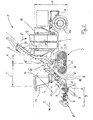
- Fig. 1 is a generally designated 1 beet harvester shown, the vehicle frame 2 is supported on the bottom side via a front and a rear chassis 3, 4.
- a harvesting crop not shown in detail with admixtures as a mixture flow G detected grinder unit 9 is provided which has a cabbage racket 5, a Tiefen Equipmentsrad 6, Rodescharen or wheels 7 and an intervening between them 8 as a major components.
- this lifting unit 9 this is in the conveying direction a mixture flow G detected Separation path T and a the separated crop in one collecting bunker 10 ein approvalnde transfer route E assigned ( Fig. 2 ).
- the self-propelled beet harvester 1 implements a machine concept in which the mixture flow G received by the lifting unit 9 can be absorbed and displaced in a direct manner in the area of the separating and transfer line T, E without restriction and over a wide area.
- the separation and transfer line T, E in a new arrangement concept with vehicle frame 2 and collecting bunker 10 are integrated so that at least the separated crop can be guided without deflection and gently displaced to the collection bunker 10.
- the plan view of the beet harvester 1 according to Fig. 3 illustrates that the sub-areas formed from the separation and transfer line T, E are formed with substantially constant transport width.
- a receiving width A for multi-row, in particular 6-row detection of beets is provided and this receiving width A continues as equal-sized transport width B on the separation distance T. It is also conceivable that the receiving width detected less than six rows of beet or 9- or 12-row recording of the crop is provided (not shown).
- All of the above-described modules for separating the mixture are arranged in front of the area of the collecting bunker 10 so that the separating and transfer routes T and E extend substantially above the front chassis 3 of the vehicle frame 2 and thus by the inclination N of this conveyor area an optimal training the beet harvester 1 in its length and height dimension L ( Fig. 1 ) or H ( Fig. 2 ) is guaranteed.
- the transfer line E extends directly in front of the collection bunker 10 and this is set between the front chassis 3 and the rear chassis 4 on the vehicle frame 2.
- the front chassis 3 has substantially at the edge under the transfer path E extending drive wheels 12 and 13, so that in the region of the separation distance T to the ground excreted impurities are deposited substantially free falling in front of the chassis 3 on the ground.
- the rear chassis 4 has a control concept with at least one steerable wheel 14, wherein in accordance with Fig. 7 illustrated embodiment, two steering wheels 14 and 14 'may be arranged opposite one another in the region of the longitudinal center plane M.
- Fig. 4 and 5 For example, the beet harvester 1 is shown in respective front views without the cab 11 and the shroud 16.
- the effective as a cleaning section separation line T has the lower wire 15, which is covered with the overlying shroud 16.
- This band 16 is provided with a plurality of entrainment-enhancing drivers 17 ( Fig. 2 ) Mistake.
- At this screen belt 15 closes in the embodiment according to Fig. 4 a roller conveyor 18, whose in the conveying direction R according to the inclination N extending components in the form of rollers 18 'in parallel longitudinal axes M 'aligned with the longitudinal median plane M ( Fig. 2 . Fig. 4 ).
- With respective transverse rollers 19 see FIG. Fig.
- the separated crop can be displaced transversely to the central longitudinal plane M on a short transverse roller path 20, so that the individual beets are compacted for further transport to a passage region with the width C '.
- the beets on the transfer line E as a single-layer flow are detected by respective drivers 22 (FIG. Fig. 2 ) of the transfer belt 21 provided as the filling belt (arrow S) and inserted into the collecting bunker 10 (arrow S ').
- a roller conveyor 23 is provided, which is constructed entirely of respective transverse rollers 23 ', so that respective already in Fig. 2 shown transverse rollers 19 end of this section are integrated into this cross roller system so that at the end of the cross roller section 20 (at 19) the passage width C 'for the individual beets can be reached and the filling of the narrower transfer belt 21 in the respective driver 22 (FIG. Fig. 2 ) he follows.
- the transfer belt 21 is in the vicinity of the collection bunker 10 as a pivotal unit (dashed line in FIG Fig. 2 ), so that a portion 21 'of the transfer belt 21 in accordance with the level of the collection bunker 10 in this in or out of this can be swung out (arrow D, Fig. 2 ).
- the collection bunker 10 has a laterally arranged discharge conveyor 10 'and, on the other hand, the collection bunker 10 can be enlarged in its receiving volume by foldable wall parts 10 ".
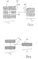
- Fig. 6 the vehicle frame 2 is illustrated in a single representation, in conjunction with Fig. 7 becomes clear that the vehicle frame 2 in the region of the front chassis 3 has two parallel to the central longitudinal plane M outer support struts 24 and 25, which form a stiffened by cross beams double central frame.
- This vehicle frame 2 is in the area of the front end faces 26 as a cross member, a driver's cab 11 ( Fig. 2 ) under cross-supporting tube 27 assigned.
- a free space 30 is formed to the region of a front transverse axis 28 of the chassis 3 or to a running in the vicinity of the center transverse strut 29 of the vehicle frame 2, which is penetrated by the oblique assemblies of the separation and transfer line T, E ( Fig. 2 ).
- the vehicle frame 2 is in the area of the front chassis 3 with respective support joints 31 (or 32, in FIG. 3) connecting at the edge to the outer support struts 24 and 25 Fig. 2 not visible), with which an upstream spring element 33 (FIG. Fig. 6 ) interacts between the vehicle frame 2 and chassis 3.
- This articulated connection of the vehicle frame 2 allows a tilting of the vehicle frame 2 by a tilt angle K, so that a tilt adjustment of the wheels is possible during the harvesting process or during a road trip.
- the top view according Fig. 7 illustrates that the vehicle frame 2 in the area behind the front free space 30 delimiting central transverse strut 29 with the outer support struts 24 and 25 in connecting regions 34 and 35 connected and each acute-angled to the central longitudinal plane M inwardly inclined strut members 36 and 37. These go in parallel to the rear chassis 4 extending longitudinal struts 38 and 39, between them extending below the collecting bunker 10 transverse struts 40, 41 are provided and the longitudinal struts 38 and 39 are connected to a rear steering fork 4 'of the swiveling to control chassis 4.
- the vehicle frame 2 is in its longitudinal contour ( Fig. 6 ) designed so that in the area between the front and rear suspension 3, 4 a bottom-side lowered contour W is formed by the strut members 38 and 39, respectively.
- a bottom-side lowered contour W is formed by the strut members 38 and 39, respectively.
- Fig. 8 the vehicle frame 2 'is shown in a second embodiment, which subsequently has a one-part central frame part 42, which adjoins the middle transverse strut 29 delimiting the free space 30, in accordance with the in FIG Fig. 6 shown longitudinal profile W is contoured and extends substantially as a one-piece longitudinal member 43.
- the space required for the implementation of the conveyor line T, E in the area 30 in front of the front chassis 3 is also realized in this embodiment, so that the arrangement of in Fig. 7 shown struts and support parts accordingly.
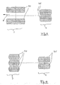
- Fig. 9 is one of the wheel variant according to Fig. 7 corresponding arrangement with two wheels 44 and 45 shown on the trolleys 3 and 4, in Fig. 10 has that front landing gear 3 three support wheels 44 of smaller diameter than in Fig. 9 on and in Fig. 11 are two centrally arranged one behind the other front support wheels 44 combined with two outer support crawlers 46.
- the rear chassis 4 is provided with only one support bead 47, which is in the direction of travel F substantially between the two lanes of two front support rollers 46 can be unrolled.
- the above-described embodiment of the beet harvester 1 with separation and transfer line T, E can also be designed in a non-illustrated embodiment, that the position of the collecting bunker 10 is changed on the vehicle frame 2 and the conveyor belts 15, 16, 20 and / or 22 at least partially under a correspondingly modified bunker (not shown) are passed, so that the material flow can be conveyed from the back of it into the plenum.
Landscapes
- Life Sciences & Earth Sciences (AREA)
- Environmental Sciences (AREA)
- Harvesting Machines For Root Crops (AREA)
- Medicines Containing Plant Substances (AREA)
- Agricultural Chemicals And Associated Chemicals (AREA)
- Control Of Position, Course, Altitude, Or Attitude Of Moving Bodies (AREA)
Applications Claiming Priority (2)
| Application Number | Priority Date | Filing Date | Title |
|---|---|---|---|
| DE10246254 | 2002-10-02 | ||
| DE10246254A DE10246254B4 (de) | 2002-10-02 | 2002-10-02 | Selbstfahrende Rübenerntemaschine |
Publications (2)
| Publication Number | Publication Date |
|---|---|
| EP1405554A1 EP1405554A1 (de) | 2004-04-07 |
| EP1405554B1 true EP1405554B1 (de) | 2011-05-11 |
Family
ID=31984383
Family Applications (1)
| Application Number | Title | Priority Date | Filing Date |
|---|---|---|---|
| EP03021598A Expired - Lifetime EP1405554B1 (de) | 2002-10-02 | 2003-09-25 | Selbstfahrende Rübenerntemaschine |
Country Status (7)
| Country | Link |
|---|---|
| EP (1) | EP1405554B1 (pl) |
| AT (1) | ATE508627T1 (pl) |
| DE (1) | DE10246254B4 (pl) |
| DK (1) | DK1405554T3 (pl) |
| EA (1) | EA005443B1 (pl) |
| PL (1) | PL216212B1 (pl) |
| UA (1) | UA74632C2 (pl) |
Families Citing this family (6)
| Publication number | Priority date | Publication date | Assignee | Title |
|---|---|---|---|---|
| DE102007049377A1 (de) | 2007-10-15 | 2009-04-16 | Grimme Landmaschinenfabrik Gmbh & Co. Kg | Rübenerntemaschine, insbesondere in Form einer selbstfahrenden Vollerntemaschine |
| NL2002538C2 (nl) * | 2009-02-16 | 2010-08-17 | Basrijs B V | Rooi-inrichting. |
| DE102011120377A1 (de) * | 2011-12-07 | 2013-06-13 | Grimme Landmaschinenfabrik Gmbh & Co. Kg | Erntemaschine für Kartoffeln, Rüben o. dgl. Hackfrüchte |
| DE102014015834A1 (de) | 2014-10-28 | 2016-04-28 | Grimme Landmaschinenfabrik Gmbh & Co. Kg | Maschine zum Ernten von Hackfrüchten |
| DE102014015835A1 (de) | 2014-10-28 | 2016-04-28 | Grimme Landmaschinenfabrik Gmbh & Co. Kg | Hackfruchterntemaschine |
| CN107172952B (zh) * | 2017-06-09 | 2019-09-27 | 昆明理工大学 | 一种温室多级输送式根茎类中药材收获机 |
Family Cites Families (12)
| Publication number | Priority date | Publication date | Assignee | Title |
|---|---|---|---|---|
| DE1215988B (de) * | 1958-10-22 | 1966-05-05 | Albert Brand | Krautziehvorrichtung fuer mehrreihige Knollenfruchterntemaschinen |
| SU125433A1 (ru) * | 1959-01-09 | 1959-11-30 | Е.Г. Баженов | Свеклоуборочный агрегат |
| SU136111A1 (ru) * | 1960-07-25 | 1960-11-30 | Г.А. Мельников | Свеклоуборочный комбайн |
| US3451485A (en) * | 1966-05-05 | 1969-06-24 | Wyolt Corp | Onion harvesting machine |
| FR2172527A5 (pl) * | 1972-02-16 | 1973-09-28 | Uk Nauchno Issled | |
| BE831709A (nl) * | 1975-07-25 | 1975-11-17 | Stoll Maschf Gmbh Wilhelm | Bietenopraper met reinigingsinrichting en lader |
| SU893162A1 (ru) * | 1980-04-15 | 1981-12-30 | Украинский научно-исследовательский институт механизации и электрификации сельского хозяйства | Многор дный картофелеуборочный комбайн |
| FR2533798B1 (fr) * | 1982-09-30 | 1985-06-28 | Moreau Ets Jean | Machine a recolter des plantes alignees, telles que des betteraves |
| EP0189017B1 (fr) * | 1984-12-19 | 1989-07-26 | Julien Verstraete | Dispositif de battage pour le nettoyage de racines de végétaux |
| DE3740655A1 (de) * | 1987-12-01 | 1989-06-15 | Wilfried Niederauer | Selbstfahrendes lade- und reinigungsgeraet fuer zuckerrueben |
| DE19913438A1 (de) * | 1999-03-25 | 2000-10-05 | Franz Kleine Agrartechnik Gmbh | Rübenroder |
| ATE374518T1 (de) * | 2000-05-04 | 2007-10-15 | Holmer Maschb Gmbh | Selbstfahrende hackfruchterntemaschine |
-
2002
- 2002-10-02 DE DE10246254A patent/DE10246254B4/de not_active Expired - Fee Related
-
2003
- 2003-09-25 EP EP03021598A patent/EP1405554B1/de not_active Expired - Lifetime
- 2003-09-25 DK DK03021598.2T patent/DK1405554T3/da active
- 2003-09-25 AT AT03021598T patent/ATE508627T1/de active
- 2003-10-01 UA UA2003108901A patent/UA74632C2/uk unknown
- 2003-10-01 EA EA200300962A patent/EA005443B1/ru not_active IP Right Cessation
- 2003-10-02 PL PL362590A patent/PL216212B1/pl unknown
Also Published As
| Publication number | Publication date |
|---|---|
| PL362590A1 (pl) | 2004-04-05 |
| PL216212B1 (pl) | 2014-03-31 |
| DE10246254B4 (de) | 2006-12-28 |
| DK1405554T3 (da) | 2011-08-15 |
| EP1405554A1 (de) | 2004-04-07 |
| UA74632C2 (en) | 2006-01-16 |
| EA005443B1 (ru) | 2005-02-24 |
| DE10246254A1 (de) | 2004-04-22 |
| EA200300962A1 (ru) | 2004-04-29 |
| ATE508627T1 (de) | 2011-05-15 |
Similar Documents
| Publication | Publication Date | Title |
|---|---|---|
| EP0212174B1 (de) | Kartoffelerntemaschine | |
| EP0803178B1 (de) | Hackfruchterntemaschine | |
| DE19828813A1 (de) | Kartoffelerntemaschine | |
| DE2652162C2 (pl) | ||
| EP1405554B1 (de) | Selbstfahrende Rübenerntemaschine | |
| EP4309490A1 (de) | Reinigungszusammenbau für einen mähdrescher | |
| DE69600835T2 (de) | Rübenerntemaschine | |
| DE60009702T2 (de) | Verbesserung der Fördermittel einer Fruchterntemaschine | |
| WO2019086430A1 (de) | Verfahren zum ernten von druschfrüchten sowie dafür vorgesehene vorrichtung für eine erntemaschine | |
| EP0898869B1 (de) | Rübenerntemaschine | |
| BE1023102B1 (de) | Maschine zum mähen von stägelartigem erntegut | |
| DE69719022T2 (de) | Vorrichtung zum Führen in einer Obsterntemaschine | |
| EP0336075A1 (de) | Kartoffelerntemaschine | |
| DE2646352C2 (de) | Selbstfahrende Erntemaschine, insbesondere für Zuckerrohr | |
| EP0588027B1 (de) | Selbstfahrende zweiachsige, mehrreihige Rübenerntemaschine | |
| DE3700095C2 (de) | Kartoffelerntemaschine | |
| DE3223329A1 (de) | Maehdrescher | |
| EP0764399B1 (de) | Vertikutier- und/oder Mähmaschine | |
| DE2819101C2 (de) | Aufgesattelte Rübenerntemaschine | |
| EP0750834A1 (de) | Selbstfahrender Mähdrescher | |
| DE102022124860A1 (de) | Erntevorsatz zur Ernte stängelartiger Pflanzen | |
| DE2124777A1 (de) | Landwirtschaftliche Maschine | |
| DE29607677U1 (de) | Kartoffelerntemaschine | |
| DE2425087A1 (de) | Landwirtschaftliches ladefahrzeug | |
| DE8628640U1 (de) | Vorrichtung zum Aufnehmen von Feldfrüchten, insbesondere Rüben oder Kartoffeln |
Legal Events
| Date | Code | Title | Description |
|---|---|---|---|
| PUAI | Public reference made under article 153(3) epc to a published international application that has entered the european phase |
Free format text: ORIGINAL CODE: 0009012 |
|
| AK | Designated contracting states |
Kind code of ref document: A1 Designated state(s): AT BE BG CH CY CZ DE DK EE ES FI FR GB GR HU IE IT LI LU MC NL PT RO SE SI SK TR |
|
| AX | Request for extension of the european patent |
Extension state: AL LT LV MK |
|
| 17P | Request for examination filed |
Effective date: 20040510 |
|
| 17Q | First examination report despatched |
Effective date: 20040618 |
|
| AKX | Designation fees paid |
Designated state(s): AT BE BG CH CY CZ DE DK EE ES FI FR GB GR HU IE IT LI LU MC NL PT RO SE SI SK TR |
|
| GRAP | Despatch of communication of intention to grant a patent |
Free format text: ORIGINAL CODE: EPIDOSNIGR1 |
|
| RAP1 | Party data changed (applicant data changed or rights of an application transferred) |
Owner name: FRANZ GRIMME LANDMASCHINENFABRIK GMBH & CO. KG |
|
| GRAS | Grant fee paid |
Free format text: ORIGINAL CODE: EPIDOSNIGR3 |
|
| RAP1 | Party data changed (applicant data changed or rights of an application transferred) |
Owner name: GRIMME LANDMASCHINENFABRIK GMBH & CO. KG |
|
| GRAA | (expected) grant |
Free format text: ORIGINAL CODE: 0009210 |
|
| AK | Designated contracting states |
Kind code of ref document: B1 Designated state(s): AT BE BG CH CY CZ DE DK EE ES FI FR GB GR HU IE IT LI LU MC NL PT RO SE SI SK TR |
|
| REG | Reference to a national code |
Ref country code: GB Ref legal event code: FG4D Free format text: NOT ENGLISH |
|
| REG | Reference to a national code |
Ref country code: CH Ref legal event code: EP |
|
| REG | Reference to a national code |
Ref country code: IE Ref legal event code: FG4D |
|
| REG | Reference to a national code |
Ref country code: DE Ref legal event code: R096 Ref document number: 50313678 Country of ref document: DE Effective date: 20110622 |
|
| REG | Reference to a national code |
Ref country code: NL Ref legal event code: T3 |
|
| REG | Reference to a national code |
Ref country code: DK Ref legal event code: T3 |
|
| PG25 | Lapsed in a contracting state [announced via postgrant information from national office to epo] |
Ref country code: PT Free format text: LAPSE BECAUSE OF FAILURE TO SUBMIT A TRANSLATION OF THE DESCRIPTION OR TO PAY THE FEE WITHIN THE PRESCRIBED TIME-LIMIT Effective date: 20110912 Ref country code: SE Free format text: LAPSE BECAUSE OF FAILURE TO SUBMIT A TRANSLATION OF THE DESCRIPTION OR TO PAY THE FEE WITHIN THE PRESCRIBED TIME-LIMIT Effective date: 20110511 |
|
| PG25 | Lapsed in a contracting state [announced via postgrant information from national office to epo] |
Ref country code: SI Free format text: LAPSE BECAUSE OF FAILURE TO SUBMIT A TRANSLATION OF THE DESCRIPTION OR TO PAY THE FEE WITHIN THE PRESCRIBED TIME-LIMIT Effective date: 20110511 Ref country code: CY Free format text: LAPSE BECAUSE OF FAILURE TO SUBMIT A TRANSLATION OF THE DESCRIPTION OR TO PAY THE FEE WITHIN THE PRESCRIBED TIME-LIMIT Effective date: 20110511 Ref country code: ES Free format text: LAPSE BECAUSE OF FAILURE TO SUBMIT A TRANSLATION OF THE DESCRIPTION OR TO PAY THE FEE WITHIN THE PRESCRIBED TIME-LIMIT Effective date: 20110822 Ref country code: FI Free format text: LAPSE BECAUSE OF FAILURE TO SUBMIT A TRANSLATION OF THE DESCRIPTION OR TO PAY THE FEE WITHIN THE PRESCRIBED TIME-LIMIT Effective date: 20110511 Ref country code: GR Free format text: LAPSE BECAUSE OF FAILURE TO SUBMIT A TRANSLATION OF THE DESCRIPTION OR TO PAY THE FEE WITHIN THE PRESCRIBED TIME-LIMIT Effective date: 20110812 |
|
| REG | Reference to a national code |
Ref country code: IE Ref legal event code: FD4D |
|
| PG25 | Lapsed in a contracting state [announced via postgrant information from national office to epo] |
Ref country code: IE Free format text: LAPSE BECAUSE OF FAILURE TO SUBMIT A TRANSLATION OF THE DESCRIPTION OR TO PAY THE FEE WITHIN THE PRESCRIBED TIME-LIMIT Effective date: 20110511 Ref country code: CZ Free format text: LAPSE BECAUSE OF FAILURE TO SUBMIT A TRANSLATION OF THE DESCRIPTION OR TO PAY THE FEE WITHIN THE PRESCRIBED TIME-LIMIT Effective date: 20110511 Ref country code: EE Free format text: LAPSE BECAUSE OF FAILURE TO SUBMIT A TRANSLATION OF THE DESCRIPTION OR TO PAY THE FEE WITHIN THE PRESCRIBED TIME-LIMIT Effective date: 20110511 |
|
| PG25 | Lapsed in a contracting state [announced via postgrant information from national office to epo] |
Ref country code: RO Free format text: LAPSE BECAUSE OF FAILURE TO SUBMIT A TRANSLATION OF THE DESCRIPTION OR TO PAY THE FEE WITHIN THE PRESCRIBED TIME-LIMIT Effective date: 20110511 Ref country code: SK Free format text: LAPSE BECAUSE OF FAILURE TO SUBMIT A TRANSLATION OF THE DESCRIPTION OR TO PAY THE FEE WITHIN THE PRESCRIBED TIME-LIMIT Effective date: 20110511 |
|
| PLBE | No opposition filed within time limit |
Free format text: ORIGINAL CODE: 0009261 |
|
| STAA | Information on the status of an ep patent application or granted ep patent |
Free format text: STATUS: NO OPPOSITION FILED WITHIN TIME LIMIT |
|
| 26N | No opposition filed |
Effective date: 20120214 |
|
| PG25 | Lapsed in a contracting state [announced via postgrant information from national office to epo] |
Ref country code: MC Free format text: LAPSE BECAUSE OF NON-PAYMENT OF DUE FEES Effective date: 20110930 |
|
| REG | Reference to a national code |
Ref country code: CH Ref legal event code: PL |
|
| PG25 | Lapsed in a contracting state [announced via postgrant information from national office to epo] |
Ref country code: IT Free format text: LAPSE BECAUSE OF FAILURE TO SUBMIT A TRANSLATION OF THE DESCRIPTION OR TO PAY THE FEE WITHIN THE PRESCRIBED TIME-LIMIT Effective date: 20110511 |
|
| REG | Reference to a national code |
Ref country code: DE Ref legal event code: R097 Ref document number: 50313678 Country of ref document: DE Effective date: 20120214 |
|
| PG25 | Lapsed in a contracting state [announced via postgrant information from national office to epo] |
Ref country code: LI Free format text: LAPSE BECAUSE OF NON-PAYMENT OF DUE FEES Effective date: 20110930 Ref country code: CH Free format text: LAPSE BECAUSE OF NON-PAYMENT OF DUE FEES Effective date: 20110930 |
|
| REG | Reference to a national code |
Ref country code: AT Ref legal event code: MM01 Ref document number: 508627 Country of ref document: AT Kind code of ref document: T Effective date: 20110925 |
|
| PG25 | Lapsed in a contracting state [announced via postgrant information from national office to epo] |
Ref country code: AT Free format text: LAPSE BECAUSE OF NON-PAYMENT OF DUE FEES Effective date: 20110925 |
|
| PG25 | Lapsed in a contracting state [announced via postgrant information from national office to epo] |
Ref country code: LU Free format text: LAPSE BECAUSE OF NON-PAYMENT OF DUE FEES Effective date: 20110925 |
|
| PG25 | Lapsed in a contracting state [announced via postgrant information from national office to epo] |
Ref country code: BG Free format text: LAPSE BECAUSE OF FAILURE TO SUBMIT A TRANSLATION OF THE DESCRIPTION OR TO PAY THE FEE WITHIN THE PRESCRIBED TIME-LIMIT Effective date: 20110811 |
|
| PG25 | Lapsed in a contracting state [announced via postgrant information from national office to epo] |
Ref country code: TR Free format text: LAPSE BECAUSE OF FAILURE TO SUBMIT A TRANSLATION OF THE DESCRIPTION OR TO PAY THE FEE WITHIN THE PRESCRIBED TIME-LIMIT Effective date: 20110511 |
|
| PG25 | Lapsed in a contracting state [announced via postgrant information from national office to epo] |
Ref country code: HU Free format text: LAPSE BECAUSE OF FAILURE TO SUBMIT A TRANSLATION OF THE DESCRIPTION OR TO PAY THE FEE WITHIN THE PRESCRIBED TIME-LIMIT Effective date: 20110511 |
|
| REG | Reference to a national code |
Ref country code: FR Ref legal event code: PLFP Year of fee payment: 14 |
|
| REG | Reference to a national code |
Ref country code: FR Ref legal event code: PLFP Year of fee payment: 15 |
|
| REG | Reference to a national code |
Ref country code: FR Ref legal event code: PLFP Year of fee payment: 16 |
|
| PGFP | Annual fee paid to national office [announced via postgrant information from national office to epo] |
Ref country code: DK Payment date: 20190920 Year of fee payment: 17 Ref country code: NL Payment date: 20190923 Year of fee payment: 17 |
|
| PGFP | Annual fee paid to national office [announced via postgrant information from national office to epo] |
Ref country code: GB Payment date: 20190924 Year of fee payment: 17 |
|
| REG | Reference to a national code |
Ref country code: DK Ref legal event code: EBP Effective date: 20200930 |
|
| REG | Reference to a national code |
Ref country code: NL Ref legal event code: MM Effective date: 20201001 |
|
| GBPC | Gb: european patent ceased through non-payment of renewal fee |
Effective date: 20200925 |
|
| PG25 | Lapsed in a contracting state [announced via postgrant information from national office to epo] |
Ref country code: NL Free format text: LAPSE BECAUSE OF NON-PAYMENT OF DUE FEES Effective date: 20201001 |
|
| PG25 | Lapsed in a contracting state [announced via postgrant information from national office to epo] |
Ref country code: GB Free format text: LAPSE BECAUSE OF NON-PAYMENT OF DUE FEES Effective date: 20200925 |
|
| PG25 | Lapsed in a contracting state [announced via postgrant information from national office to epo] |
Ref country code: DK Free format text: LAPSE BECAUSE OF NON-PAYMENT OF DUE FEES Effective date: 20200930 |
|
| PGFP | Annual fee paid to national office [announced via postgrant information from national office to epo] |
Ref country code: DE Payment date: 20220621 Year of fee payment: 20 |
|
| PGFP | Annual fee paid to national office [announced via postgrant information from national office to epo] |
Ref country code: FR Payment date: 20220921 Year of fee payment: 20 Ref country code: BE Payment date: 20220921 Year of fee payment: 20 |
|
| REG | Reference to a national code |
Ref country code: DE Ref legal event code: R071 Ref document number: 50313678 Country of ref document: DE |
|
| REG | Reference to a national code |
Ref country code: BE Ref legal event code: MK Effective date: 20230925 |