EP1400725B1 - Kettenspanner - Google Patents
Kettenspanner Download PDFInfo
- Publication number
- EP1400725B1 EP1400725B1 EP03018130A EP03018130A EP1400725B1 EP 1400725 B1 EP1400725 B1 EP 1400725B1 EP 03018130 A EP03018130 A EP 03018130A EP 03018130 A EP03018130 A EP 03018130A EP 1400725 B1 EP1400725 B1 EP 1400725B1
- Authority
- EP
- European Patent Office
- Prior art keywords
- tensioner
- tensioner arm
- arm body
- transmission chain
- chain
- Prior art date
- Legal status (The legal status is an assumption and is not a legal conclusion. Google has not performed a legal analysis and makes no representation as to the accuracy of the status listed.)
- Expired - Lifetime
Links
- 230000005540 biological transmission Effects 0.000 claims description 63
- 230000008878 coupling Effects 0.000 claims description 4
- 238000010168 coupling process Methods 0.000 claims description 4
- 238000005859 coupling reaction Methods 0.000 claims description 4
- 230000010355 oscillation Effects 0.000 description 12
- 238000010521 absorption reaction Methods 0.000 description 6
- 229910000639 Spring steel Inorganic materials 0.000 description 3
- 229920003002 synthetic resin Polymers 0.000 description 3
- 239000000057 synthetic resin Substances 0.000 description 3
- 230000009471 action Effects 0.000 description 2
- 230000002401 inhibitory effect Effects 0.000 description 2
- 230000008901 benefit Effects 0.000 description 1
- 210000000078 claw Anatomy 0.000 description 1
- 230000000694 effects Effects 0.000 description 1
- 230000006872 improvement Effects 0.000 description 1
- 239000000463 material Substances 0.000 description 1
- 230000002265 prevention Effects 0.000 description 1
- 230000009467 reduction Effects 0.000 description 1
Images


Classifications
-
- F—MECHANICAL ENGINEERING; LIGHTING; HEATING; WEAPONS; BLASTING
- F16—ENGINEERING ELEMENTS AND UNITS; GENERAL MEASURES FOR PRODUCING AND MAINTAINING EFFECTIVE FUNCTIONING OF MACHINES OR INSTALLATIONS; THERMAL INSULATION IN GENERAL
- F16H—GEARING
- F16H7/00—Gearings for conveying rotary motion by endless flexible members
- F16H7/08—Means for varying tension of belts, ropes or chains
- F16H7/0848—Means for varying tension of belts, ropes or chains with means for impeding reverse motion
-
- F—MECHANICAL ENGINEERING; LIGHTING; HEATING; WEAPONS; BLASTING
- F16—ENGINEERING ELEMENTS AND UNITS; GENERAL MEASURES FOR PRODUCING AND MAINTAINING EFFECTIVE FUNCTIONING OF MACHINES OR INSTALLATIONS; THERMAL INSULATION IN GENERAL
- F16H—GEARING
- F16H7/00—Gearings for conveying rotary motion by endless flexible members
- F16H7/08—Means for varying tension of belts, ropes or chains
- F16H2007/0802—Actuators for final output members
- F16H2007/0804—Leaf springs
-
- F—MECHANICAL ENGINEERING; LIGHTING; HEATING; WEAPONS; BLASTING
- F16—ENGINEERING ELEMENTS AND UNITS; GENERAL MEASURES FOR PRODUCING AND MAINTAINING EFFECTIVE FUNCTIONING OF MACHINES OR INSTALLATIONS; THERMAL INSULATION IN GENERAL
- F16H—GEARING
- F16H7/00—Gearings for conveying rotary motion by endless flexible members
- F16H7/08—Means for varying tension of belts, ropes or chains
- F16H2007/0802—Actuators for final output members
- F16H2007/0812—Fluid pressure
-
- F—MECHANICAL ENGINEERING; LIGHTING; HEATING; WEAPONS; BLASTING
- F16—ENGINEERING ELEMENTS AND UNITS; GENERAL MEASURES FOR PRODUCING AND MAINTAINING EFFECTIVE FUNCTIONING OF MACHINES OR INSTALLATIONS; THERMAL INSULATION IN GENERAL
- F16H—GEARING
- F16H7/00—Gearings for conveying rotary motion by endless flexible members
- F16H7/08—Means for varying tension of belts, ropes or chains
- F16H7/0848—Means for varying tension of belts, ropes or chains with means for impeding reverse motion
- F16H2007/0859—Check valves
-
- F—MECHANICAL ENGINEERING; LIGHTING; HEATING; WEAPONS; BLASTING
- F16—ENGINEERING ELEMENTS AND UNITS; GENERAL MEASURES FOR PRODUCING AND MAINTAINING EFFECTIVE FUNCTIONING OF MACHINES OR INSTALLATIONS; THERMAL INSULATION IN GENERAL
- F16H—GEARING
- F16H7/00—Gearings for conveying rotary motion by endless flexible members
- F16H7/08—Means for varying tension of belts, ropes or chains
- F16H2007/0863—Finally actuated members, e.g. constructional details thereof
- F16H2007/0872—Sliding members
Definitions
- the present invention relates to a chain tensioner according to the preamble of claim 1, provided with a tensioner arm rockably supported via a pivot, having a longitudinal axis, by a fixed structure and relatively slidably touched to the outside on the loose side of an endless transmission chain coupling a driving sprocket and a driven sprocket, and a tensioner lifter supported by the fixed structure for pressing the end of the tensioner arm on the side of the transmission chain, and particularly relates to the improvement of a chain tensioner the tensioner arm of which is composed of a band tensioner arm body curved toward the transmission chain.
- a tensioner arm is formed by a band elastic member curved toward a transmission chain.
- JP 07-151197 A a chain tensioner in which the width of the middle of a tensioner arm is set to a smaller value than the width of each end is disclosed and as the tensioner arm is rigid and in addition, the middle is directly slidingly touched to a transmission chain, the chain tensioner is not an object of the invention.
- a chain tensioner in which a tensioner arm is formed by a band elastic member curved toward a transmission chain has an advantage that the oscillation of the transmission chain can be absorbed by the deflection of the tensioner arm, however, as inaconventional type, the tensioner arm is directly slidingly touched to the transmission chain, a problem that surface pressure between the tensioner arm and the transmission chain increases and the wear resistance of the tensioner arm is deteriorated when narrowing the width of the middle of the tensioner arm is tried, the enhancement of the flexibility of the middle is tried and the enhancement of an oscillation absorption function for the transmission chain is tried occurs.
- a chain tensioner according to the preamble of claim 1 is known from JP 2000-97300 A .
- the invention is based upon a tensioner provided with a tensioner arm rockably supported via a pivot, having a longitudinal axis, by a fixed structure and relatively slidably touched to the outside on the loose side of an endlesss transmission chain coupling a driving sprocket and a driven sprocket, and a tensioner lifter supported by the fixed structure for pressing the end of the tensioner arm on the side of the transmission chain, wherein the tensioner arm is composed of a band tensioner arm body curved toward the transmission chain and a flexible tensioner shoe that covers the front of the tensioner arm body and has a chain guide groove to the front of which the transmission chain is slidably fitted and the width of the middle in the longitudinal direction of the tensioner arm body is set to a smaller value than the width of each end of the arm body.
- the fixed structure corresponds to an engine body Ea in embodiments described later of the invention.
- an oscillation absorption function for the transmission chain can be enhanced and the width of the tensioner arm body is different in each part, the natural frequency of the tensioner arm body is different in each part and the resonance of the tensioner arm body can be also prevented.
- an arc -shaped cut-out may be formed on both sides of the middle to set the width of the middle of the tensioner arm body to a small value.
- desired flexibility can be simply applied to the middle of the tensioner arm body by selecting the depth and the number of cut-outs.
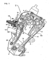
- Fig. 1 is a side view showing a timing transmission gear for a valve gear of an engine provided with a chain tensioner according to the invention
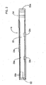
- Fig. 2 is a plan showing a tensioner arm of the chain tensioner
- Fig. 3 is a side view showing the tensioner arm
- Fig. 4 is a sectional view viewed along a line 4-4 in Fig. 3
- Fig. 5 is a sectional view viewed along a line 5-5 in Fig. 3
- Fig. 6 is a sectional view viewed along a line 6-6 in Fig. 3
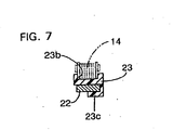
- Fig. 7 is a sectional view viewed along a line 7-7 in Fig. 3
- Fig. 8 is a plan showing the body of the tensioner arm
- Fig. 9 is a side view showing the body of the tensioner arm
- Fig. 10 shows another embodiment of the invention corresponding to Fig. 8 .
- an engine E for a motorcycle is arranged in a state in which the head is inclined in front of a vehicle.
- the body Ea of the engine E is composed of a crankcase 1, a cylinder block 2 and a cylinder head 3, a crankshaft 4 is supported by the crankcase 1, a camshaft for intake air 5 and a camshaft for exhaust 6 are supported by the cylinder head 3, and the crankshaft 4, the camshaft for intake air 5 and the camshaft for exhaust 6 are coupled by a timing transmission gear 10.
- the timing transmission gear 10 is composed of a driving sprocket 11 fixed to the crankshaft 4, first and second driven sprockets 12, 13 respectively fixed to the camshaft for intake air 5 and the camshaft for exhaust 6 and a transmission chain 14 without an end wound on the driving sprocket 11, the first and second driven sprockets 12, 13.
- the first and second driven sprockets 12, 13 both have double teeth of the number of the teeth of the driving sprocket 11 and are driven in a direction shown by an arrow A at half reduction ratio from the driving sprocket 11.
- a chain tensioner 15 On the loose side of the transmission chain 14, a chain tensioner 15 according to the invention for applying fixed tension to it is arranged.
- the chain tensioner 15 is composed of a tensioner arm 16, a control arm 17 and a tensioner lifter 18.
- the tensioner arm 16 is composed of a band tensioner arm body 22 rockably supported in the vicinity of the driving sprocket 11 via a first pivot 20 by the cylinder block 2 and made of a spring steel plate curved toward the outside of the loose side of the transmission chain 14 and a flexible tensioner shoe 23 made of synthetic resin that covers the front of the tensioner arm body 22 and is slidingly touched to the outside of the loose side of the transmission chain 14.
- the tensioner arm body 22 and the tensioner shoe 23 are respectively provided with a boss 22a and a boss 23a supported via a collar 24 by the first pivot 20 at each end, a chain guide groove 23b to which the loose side of the transmission chain 14 is fitted so that the loose side can be slid is formed on the front of the tensioner shoe 23 and at the back of the tensioner shoe, plural holding claws 23c that hold the tensioner arm body 22 lapped over the tensioner shoe are formed.
- an arc-shaped cut-out 25 is formed in the middle from the first pivot 20 to a point N pressed by the control arm 17 on both sides of the tensioner arm body 22 and hereby, the width in the middle of the tensioner arm body 22 is set so that it is smaller than the width at both ends of the arm body 22.
- the control arm 17 is made of a spring steel plate like the tensioner arm body 22, is supported in the vicinity of the first driven sprocket 12 via a second pivot 21 by the cylinder head 3 so that the control arm can be oscillated and the oscillated end is touched to the back on the side of the oscillated end of the tensioner arm body 22.
- a pressure plate 27 is bonded to the back in the middle of the control arm 17 via cushion material 26 such as rubber and the tensioner lifter 18 for pressing the pressure plate 27 on the side of the tensioner arm 16 is attached to the cylinder head 3.
- a point P of the application of the pressure of the tensioner lifter 18 upon the control arm 17 is set in the middle of the center O of the second pivot 21 which is the center of the oscillation of the control arm 17 and the pressure point N of the control arm 17 upon the tensioner arm 16.
- the control arm 17 is provided with an auxiliary shoe 28 made of synthetic resin and slidingly touched to the outside of the transmission chain 14 between the first driven sprocket 12 and the end of the tensioner arm 16.
- the tensioner lifter 18 is composed of a lifter case 29 fixed to the cylinder head 3, a hollow lifter rod 30 supported by the lifter case 29 so that the rod cannot be turned and opposite to the pressure plate 27, a screw shaft 31 screwed to a hollow part of the lifter rod 30 and a twisted coil spring 32 for turning and pressing the screw shaft 31 in a traveling direction of the lifter rod 30 in the lifter case 29 as heretofore well-known. Therefore, the torsional moment of the twisted coil spring 32 is converted to a thrust load by the screw shaft 31 and is amplified to be pressure that presses the lifter rod 30 on the side of the control arm 17.
- timing transmission gear 10 While the timing transmission gear 10 is operated, that is, when the driving sprocket 11 drives the first and second driven sprockets 12, 13 via the transmission chain 14, the engaged state of each sprocket 11 to 13 of the transmission chain 14 is always kept suitable and efficient chain transmission is achieved by transmitting pressure which the tensioner lifter 18 applies to the pressure plate 27 of the control arm 17 by the lifter rod 30 to the tensioner arm 16 via the control arm 17, transmitting it to the loose side of the transmission chain 14 and applying fixed tension to the transmission chain 14.
- the oscillation can be absorbed by the pressure of the tensioner lifter 18 and the suitable deflection of the control arm 17 and the tensioner arm 16.
- the tensioner lifter 18 can suitably fulfill an oscillation inhibiting function for the transmission chain 14 and the useful life can be extended.
- the tensioner arm 16 can be greatly moved via the control arm 17 at a relatively small stroke of the lifter rod 30 of the tensioner lifter 18 owing to the arm ratio of the control arm 17, as a result, the follow-up of the lifter rod 30 for the extension of the transmission chain 14 is enhanced, the tensioner lifter 18 canmore suitably fulfill the oscillation inhibiting function for the transmission chain 14 in cooperation with a fact that the repulsion of the transmission chain 14 is not directly transmitted to the tensioner lifter 18 and the life can be further extended.
- control arm 17 presses the auxiliary shoe 28 upon the outside of the transmission chain 14 between the first driven sprocket 12 and the tensioner arm 16 by the pressure of the tensioner lifter 18, contact ratio between the transmission chain 14 and the first driven sprocket 12 is enhanced and the control arm contributes to the enhancement of chain transmission efficiency.
- the tensioner arm 16 is composed of the tensioner arm body 22 made of a spring steel plate and the flexible tensioner shoe 23 made of synthetic resin that covers the front of the tensioner arm body 22 and is directly slidingly touched to the transmission chain 14 and the arc-shaped cut-out 25 the width of which is smaller than the width of each end is provided on both sides of the middle of the tensioner arm body 22, the flexibility in the middle of the tensioner arm body 22 is enhanced, the oscillation absorption function for the transmission chain 14 can be enhanced, the natural frequency of the tensioner arm body 22 is different in each part because the width of the tensioner arm body 22 is different in each part and the tensioner arm can also contribute to the prevention of the resonance of the tensioner arm body 22.
- desired flexibility can be simply applied to the middle of the tensioner arm body 22 by selecting the depth and the number of the cut-outs 25.
- FIG. 10 of the invention is characterized in that the width of a tensioner arm body 22 is gradually reduced from both ends of the arm body 22 toward the center, and as the configuration of the others is similar to that in the above-mentioned embodiment, the same reference number is allocated to a part corresponding to that in the previous embodiment in Fig. 10 and the description is omitted. In this embodiment, the similar action and effect to those in the previous embodiment can be also achieved.
- the pressure of the tensioner lifter 18 may be also to directly act upon the back at the end of the tensioner arm 16 without using the control arm 17.
- the tensioner arm is composed of the elastic band tensioner arm body curved toward the transmission chain and the flexible tensioner shoe covering the front of the tensioner arm body and having the chain guide groove to the front of which the transmission chain is slidably fitted so that the transmission chain can be slid and the width of the middle in the longitudinal direction of the tensioner arm body is set so that the width is smaller than the width of each end of the arm body, the flexibility of the middle of the tensioner arm body is enhanced, the oscillation absorption function for the transmission chain can be enhanced, the natural frequency of the tensioner arm body is different in each part because the width of the tensioner arm body is different in each part and the resonance of
- the arc-shaped cut-out is formed on both sides of the middle to set the width of the middle of the tensioner arm body to a smaller value, desired flexibility can be simply applied to the middle of the tensioner arm body by selecting the depth and the number of cut-outs.
- a tensioner arm 16 is composed of an elastic band tensioner arm body 22 curved toward a transmission chain 14 and a flexible tensioner shoe 23 which covers the front of the tensioner arm body 22 and which is provided with a chain guide groove 23b to the front of which the transmission chain 14 is slidably fitted and, and the width of the middle in the longitudinal direction of the tensioner arm body 22 is set so that the width is smaller than the width of each end of the arm body 22.
Landscapes
- Engineering & Computer Science (AREA)
- General Engineering & Computer Science (AREA)
- Mechanical Engineering (AREA)
- Devices For Conveying Motion By Means Of Endless Flexible Members (AREA)
Claims (2)
- Kettenspanner, welcher versehen ist mit einem Spannerarm (16), welcher schwenkbar über einen Zapfen (20) mit einer Längsachse an einer festen Struktur (Ea) gelagert ist und mit der Außenseite auf der lockeren Seite einer endlosen Getriebekette (14), welche ein Antriebskettenrad (11) und ein Abtriebskettenrad (12) koppelt, relativ verschiebbar in Berührung steht, und einem Spannerausheber (18), welcher an der festen Struktur (Ea) gelagert ist, um das Ende des Spannerarms (16) auf die Seite der Getriebekette (14) zu pressen, wobei:der Spannerarm (16) aus einem Band-Spannerarmkörper (22), welcher zu der Getriebekette (14) hin gekrümmt ist, und einem flexiblen Spannerschuh (23), welcher die Vorderseite des Spannerarmkörpers (22) abdeckt und eine Kettenführungsnut (23b) hat, an deren Vorderseite die Getriebekette (14) verschiebbar angebracht ist, besteht; unddie Breite von der Mitte in der Längsrichtung des Spannerarmkörpers (22) auf einen kleineren Wert gesetzt ist als die Breite von jedem Ende von dem Armkörper (22),dadurch gekennzeichnet,
dass der Band-Spannerarmkörper (22) ein elastischer Band-Spannerarmkörper (22) ist, und
dass die Breite des Spannerarmkörpers (22), welche sich in der Richtung der Längsachse des Zapfens (20) erstreckt, von jedem Ende des Spannerarmkörpers (22) zu der Mitte hin allmählich reduziert ist. - Kettenspanner nach Anspruch 1, wobei:ein bogenförmiger Ausschnitt (25) auf beiden Seiten von der Mitte ausgebildet ist, um die Breite der Mitte des Spannerarmkörpers (22) auf einen kleinen Wert zu setzen.
Applications Claiming Priority (2)
| Application Number | Priority Date | Filing Date | Title |
|---|---|---|---|
| JP2002265193A JP3999610B2 (ja) | 2002-09-11 | 2002-09-11 | チェーンテンショナ装置 |
| JP2002265193 | 2002-09-11 |
Publications (3)
| Publication Number | Publication Date |
|---|---|
| EP1400725A2 EP1400725A2 (de) | 2004-03-24 |
| EP1400725A3 EP1400725A3 (de) | 2004-06-23 |
| EP1400725B1 true EP1400725B1 (de) | 2010-06-02 |
Family
ID=31944487
Family Applications (1)
| Application Number | Title | Priority Date | Filing Date |
|---|---|---|---|
| EP03018130A Expired - Lifetime EP1400725B1 (de) | 2002-09-11 | 2003-08-08 | Kettenspanner |
Country Status (4)
| Country | Link |
|---|---|
| US (1) | US7018312B2 (de) |
| EP (1) | EP1400725B1 (de) |
| JP (1) | JP3999610B2 (de) |
| DE (1) | DE60332801D1 (de) |
Cited By (1)
| Publication number | Priority date | Publication date | Assignee | Title |
|---|---|---|---|---|
| CN104565245A (zh) * | 2013-10-28 | 2015-04-29 | 舍弗勒技术有限两合公司 | 用于链的排气和喷油的张紧轨的压力件 |
Families Citing this family (14)
| Publication number | Priority date | Publication date | Assignee | Title |
|---|---|---|---|---|
| JP4573901B2 (ja) | 2008-04-14 | 2010-11-04 | 本田技研工業株式会社 | チェーンテンショナ装置 |
| JP5460742B2 (ja) * | 2009-02-27 | 2014-04-02 | ボーグワーナー インコーポレーテッド | 自動車のタイミングチェーンシステム構成要素およびその方法 |
| JP5143200B2 (ja) * | 2009-09-09 | 2013-02-13 | 本田技研工業株式会社 | チェーンテンショナ装置 |
| JP5611145B2 (ja) * | 2011-08-02 | 2014-10-22 | 株式会社椿本チエイン | 伝動装置用ガイド |
| JP5631825B2 (ja) * | 2011-09-07 | 2014-11-26 | 株式会社椿本チエイン | 伝動装置用ガイド |
| CN103148183B (zh) * | 2011-12-07 | 2017-10-24 | 舍弗勒技术股份两合公司 | 用于连续牵引机构的板簧张紧器 |
| JP2014145398A (ja) * | 2013-01-28 | 2014-08-14 | Tsubakimoto Chain Co | チェーンガイド |
| JP2014177988A (ja) * | 2013-03-14 | 2014-09-25 | Tsubakimoto Chain Co | チェーンガイド |
| DE102015008877A1 (de) * | 2015-07-08 | 2016-08-04 | Iwis Motorsysteme Gmbh & Co. Kg | Modulare Gleit- oder Spannschiene |
| US9850989B2 (en) * | 2014-10-22 | 2017-12-26 | Schaeffler Technologies AG & Co. KG | Compliant tensioner arm |
| JP6408974B2 (ja) * | 2015-10-21 | 2018-10-17 | 株式会社椿本チエイン | チェーンガイド |
| JP6788181B2 (ja) * | 2016-08-04 | 2020-11-25 | 株式会社椿本チエイン | チェーン伝動装置 |
| JP7277732B2 (ja) * | 2019-05-15 | 2023-05-19 | 株式会社椿本チエイン | テンショナレバー |
| DE102019118025A1 (de) * | 2019-07-04 | 2021-01-07 | Schaeffler Technologies AG & Co. KG | Gleitschiene für ein Umschlingungsgetriebe |
Family Cites Families (8)
| Publication number | Priority date | Publication date | Assignee | Title |
|---|---|---|---|---|
| JPH02296046A (ja) | 1989-05-09 | 1990-12-06 | Yamaha Motor Co Ltd | チェーンテンショナー |
| JPH07151197A (ja) | 1993-11-26 | 1995-06-13 | Suzuki Motor Corp | チエーンテンショナ |
| JP2000097300A (ja) | 1998-09-24 | 2000-04-04 | Borg Warner Automotive Kk | チェーンテンショナアームおよびチェーンガイド |
| US6612952B1 (en) * | 1999-10-28 | 2003-09-02 | Borgwarner Inc. | Blade tensioner having spring blade cantilevered from distal end of arm |
| JP2001227605A (ja) * | 2000-02-15 | 2001-08-24 | Ntn Corp | チェーンレバー |
| AU2002219842A1 (en) * | 2000-11-17 | 2002-05-27 | Cloyes Gear And Products, Inc. | Snap-fit chain guide with locking connector arrangement |
| JP4065169B2 (ja) * | 2002-09-11 | 2008-03-19 | 本田技研工業株式会社 | チェーンテンショナ装置 |
| US6939259B2 (en) * | 2003-04-25 | 2005-09-06 | Borgwarner Inc. | Two-shot unified chain tensioner arm or guide |
-
2002
- 2002-09-11 JP JP2002265193A patent/JP3999610B2/ja not_active Expired - Fee Related
-
2003
- 2003-08-08 DE DE60332801T patent/DE60332801D1/de not_active Expired - Lifetime
- 2003-08-08 EP EP03018130A patent/EP1400725B1/de not_active Expired - Lifetime
- 2003-08-25 US US10/646,744 patent/US7018312B2/en not_active Expired - Fee Related
Cited By (2)
| Publication number | Priority date | Publication date | Assignee | Title |
|---|---|---|---|---|
| CN104565245A (zh) * | 2013-10-28 | 2015-04-29 | 舍弗勒技术有限两合公司 | 用于链的排气和喷油的张紧轨的压力件 |
| CN104565245B (zh) * | 2013-10-28 | 2019-11-29 | 舍弗勒技术股份两合公司 | 用于链的排气和喷油的张紧轨的压力件 |
Also Published As
| Publication number | Publication date |
|---|---|
| JP3999610B2 (ja) | 2007-10-31 |
| JP2004100856A (ja) | 2004-04-02 |
| EP1400725A2 (de) | 2004-03-24 |
| US20040106484A1 (en) | 2004-06-03 |
| DE60332801D1 (de) | 2010-07-15 |
| US7018312B2 (en) | 2006-03-28 |
| EP1400725A3 (de) | 2004-06-23 |
Similar Documents
| Publication | Publication Date | Title |
|---|---|---|
| EP1400725B1 (de) | Kettenspanner | |
| EP1398538B1 (de) | Kettenspannvorrichtung | |
| US6612952B1 (en) | Blade tensioner having spring blade cantilevered from distal end of arm | |
| EP1715217B1 (de) | Mechanischer Kettenspanner mit Rasteinrichtung | |
| US6375587B1 (en) | Timing chain having multiple blade tensioners contacting the same section of chain | |
| EP1915550B1 (de) | Mechanischer schwenkspanner mit querstrangdämpfung | |
| US5846150A (en) | Guide posts for guiding and damping chain movement | |
| JP2000179633A (ja) | タイミングシステムおよびエンジンタイミングシステム | |
| KR100235450B1 (ko) | 동시전동벨트용 자동텐셔너 | |
| JPH10231905A (ja) | チェーン張力緩和装置 | |
| US20020042315A1 (en) | Chain or belt tensioner arm | |
| US4776307A (en) | Multi-cylinder/combustion engine | |
| JP3149876B1 (ja) | 内燃機関のチェーンテンショナ装置 | |
| JPH1068452A (ja) | チェーンのテンショナー | |
| EP1496290B1 (de) | Kettenspanner für eine Verteilerkette | |
| JP4466027B2 (ja) | 内置き型テンショナー装置 | |
| JP3755132B2 (ja) | チェーン用ブレードテンショナシステム | |
| KR100534702B1 (ko) | V형 엔진의 체인 구동 시스템 | |
| JPH0914363A (ja) | チェーンアジャスタ | |
| JPH07117129B2 (ja) | 頭上カム軸式エンジンのチエ−ンガイド | |
| US7404777B2 (en) | Power transmission incorporating tensioner lever | |
| KR100216439B1 (ko) | 벨트 체결구조 | |
| JPH10281243A (ja) | エンジンのチェーンガイド | |
| JPH0211255U (de) | ||
| JPH02283818A (ja) | チェーンガイドの取付構造 |
Legal Events
| Date | Code | Title | Description |
|---|---|---|---|
| PUAI | Public reference made under article 153(3) epc to a published international application that has entered the european phase |
Free format text: ORIGINAL CODE: 0009012 |
|
| AK | Designated contracting states |
Kind code of ref document: A2 Designated state(s): AT BE BG CH CY CZ DE DK EE ES FI FR GB GR HU IE IT LI LU MC NL PT RO SE SI SK TR |
|
| AX | Request for extension of the european patent |
Extension state: AL LT LV MK |
|
| PUAL | Search report despatched |
Free format text: ORIGINAL CODE: 0009013 |
|
| AK | Designated contracting states |
Kind code of ref document: A3 Designated state(s): AT BE BG CH CY CZ DE DK EE ES FI FR GB GR HU IE IT LI LU MC NL PT RO SE SI SK TR |
|
| AX | Request for extension of the european patent |
Extension state: AL LT LV MK |
|
| 17P | Request for examination filed |
Effective date: 20040810 |
|
| AKX | Designation fees paid |
Designated state(s): DE ES FR GB IT |
|
| 17Q | First examination report despatched |
Effective date: 20080923 |
|
| GRAP | Despatch of communication of intention to grant a patent |
Free format text: ORIGINAL CODE: EPIDOSNIGR1 |
|
| GRAS | Grant fee paid |
Free format text: ORIGINAL CODE: EPIDOSNIGR3 |
|
| GRAA | (expected) grant |
Free format text: ORIGINAL CODE: 0009210 |
|
| AK | Designated contracting states |
Kind code of ref document: B1 Designated state(s): DE ES FR GB IT |
|
| REG | Reference to a national code |
Ref country code: GB Ref legal event code: FG4D |
|
| REF | Corresponds to: |
Ref document number: 60332801 Country of ref document: DE Date of ref document: 20100715 Kind code of ref document: P |
|
| PLBE | No opposition filed within time limit |
Free format text: ORIGINAL CODE: 0009261 |
|
| STAA | Information on the status of an ep patent application or granted ep patent |
Free format text: STATUS: NO OPPOSITION FILED WITHIN TIME LIMIT |
|
| 26N | No opposition filed |
Effective date: 20110303 |
|
| REG | Reference to a national code |
Ref country code: FR Ref legal event code: ST Effective date: 20110502 |
|
| GBPC | Gb: european patent ceased through non-payment of renewal fee |
Effective date: 20100902 |
|
| REG | Reference to a national code |
Ref country code: DE Ref legal event code: R097 Ref document number: 60332801 Country of ref document: DE Effective date: 20110302 |
|
| PG25 | Lapsed in a contracting state [announced via postgrant information from national office to epo] |
Ref country code: FR Free format text: LAPSE BECAUSE OF NON-PAYMENT OF DUE FEES Effective date: 20100831 |
|
| PG25 | Lapsed in a contracting state [announced via postgrant information from national office to epo] |
Ref country code: GB Free format text: LAPSE BECAUSE OF NON-PAYMENT OF DUE FEES Effective date: 20100902 |
|
| PGFP | Annual fee paid to national office [announced via postgrant information from national office to epo] |
Ref country code: IT Payment date: 20110811 Year of fee payment: 9 |
|
| REG | Reference to a national code |
Ref country code: DE Ref legal event code: R084 Ref document number: 60332801 Country of ref document: DE Effective date: 20120523 |
|
| PG25 | Lapsed in a contracting state [announced via postgrant information from national office to epo] |
Ref country code: IT Free format text: LAPSE BECAUSE OF NON-PAYMENT OF DUE FEES Effective date: 20120808 |
|
| PG25 | Lapsed in a contracting state [announced via postgrant information from national office to epo] |
Ref country code: ES Free format text: LAPSE BECAUSE OF FAILURE TO SUBMIT A TRANSLATION OF THE DESCRIPTION OR TO PAY THE FEE WITHIN THE PRESCRIBED TIME-LIMIT Effective date: 20100913 |
|
| PGFP | Annual fee paid to national office [announced via postgrant information from national office to epo] |
Ref country code: DE Payment date: 20130731 Year of fee payment: 11 |
|
| REG | Reference to a national code |
Ref country code: DE Ref legal event code: R119 Ref document number: 60332801 Country of ref document: DE |
|
| REG | Reference to a national code |
Ref country code: DE Ref legal event code: R119 Ref document number: 60332801 Country of ref document: DE Effective date: 20150303 |
|
| PG25 | Lapsed in a contracting state [announced via postgrant information from national office to epo] |
Ref country code: DE Free format text: LAPSE BECAUSE OF NON-PAYMENT OF DUE FEES Effective date: 20150303 |