EP1398511A1 - Vorrichtung zur lokalen Kühlung oder Erwärmung eines Gegenstandes - Google Patents
Vorrichtung zur lokalen Kühlung oder Erwärmung eines Gegenstandes Download PDFInfo
- Publication number
- EP1398511A1 EP1398511A1 EP03019804A EP03019804A EP1398511A1 EP 1398511 A1 EP1398511 A1 EP 1398511A1 EP 03019804 A EP03019804 A EP 03019804A EP 03019804 A EP03019804 A EP 03019804A EP 1398511 A1 EP1398511 A1 EP 1398511A1
- Authority
- EP
- European Patent Office
- Prior art keywords
- contact element
- thermal contact
- circulation pump
- housing
- circulating pump
- Prior art date
- Legal status (The legal status is an assumption and is not a legal conclusion. Google has not performed a legal analysis and makes no representation as to the accuracy of the status listed.)
- Granted
Links
Images

Classifications
-
- F—MECHANICAL ENGINEERING; LIGHTING; HEATING; WEAPONS; BLASTING
- F04—POSITIVE - DISPLACEMENT MACHINES FOR LIQUIDS; PUMPS FOR LIQUIDS OR ELASTIC FLUIDS
- F04D—NON-POSITIVE-DISPLACEMENT PUMPS
- F04D29/00—Details, component parts, or accessories
- F04D29/58—Cooling; Heating; Diminishing heat transfer
- F04D29/586—Cooling; Heating; Diminishing heat transfer specially adapted for liquid pumps
- F04D29/588—Cooling; Heating; Diminishing heat transfer specially adapted for liquid pumps cooling or heating the machine
-
- F—MECHANICAL ENGINEERING; LIGHTING; HEATING; WEAPONS; BLASTING
- F04—POSITIVE - DISPLACEMENT MACHINES FOR LIQUIDS; PUMPS FOR LIQUIDS OR ELASTIC FLUIDS
- F04D—NON-POSITIVE-DISPLACEMENT PUMPS
- F04D13/00—Pumping installations or systems
- F04D13/02—Units comprising pumps and their driving means
- F04D13/06—Units comprising pumps and their driving means the pump being electrically driven
- F04D13/0606—Canned motor pumps
-
- F—MECHANICAL ENGINEERING; LIGHTING; HEATING; WEAPONS; BLASTING
- F04—POSITIVE - DISPLACEMENT MACHINES FOR LIQUIDS; PUMPS FOR LIQUIDS OR ELASTIC FLUIDS
- F04D—NON-POSITIVE-DISPLACEMENT PUMPS
- F04D29/00—Details, component parts, or accessories
- F04D29/58—Cooling; Heating; Diminishing heat transfer
- F04D29/586—Cooling; Heating; Diminishing heat transfer specially adapted for liquid pumps
-
- G—PHYSICS
- G06—COMPUTING OR CALCULATING; COUNTING
- G06F—ELECTRIC DIGITAL DATA PROCESSING
- G06F1/00—Details not covered by groups G06F3/00 - G06F13/00 and G06F21/00
- G06F1/16—Constructional details or arrangements
- G06F1/20—Cooling means
-
- G—PHYSICS
- G06—COMPUTING OR CALCULATING; COUNTING
- G06F—ELECTRIC DIGITAL DATA PROCESSING
- G06F1/00—Details not covered by groups G06F3/00 - G06F13/00 and G06F21/00
- G06F1/16—Constructional details or arrangements
- G06F1/20—Cooling means
- G06F1/206—Cooling means comprising thermal management
-
- H—ELECTRICITY
- H10—SEMICONDUCTOR DEVICES; ELECTRIC SOLID-STATE DEVICES NOT OTHERWISE PROVIDED FOR
- H10W—GENERIC PACKAGES, INTERCONNECTIONS, CONNECTORS OR OTHER CONSTRUCTIONAL DETAILS OF DEVICES COVERED BY CLASS H10
- H10W40/00—Arrangements for thermal protection or thermal control
- H10W40/40—Arrangements for thermal protection or thermal control involving heat exchange by flowing fluids
- H10W40/47—Arrangements for thermal protection or thermal control involving heat exchange by flowing fluids by flowing liquids, e.g. forced water cooling
-
- F—MECHANICAL ENGINEERING; LIGHTING; HEATING; WEAPONS; BLASTING
- F28—HEAT EXCHANGE IN GENERAL
- F28D—HEAT-EXCHANGE APPARATUS, NOT PROVIDED FOR IN ANOTHER SUBCLASS, IN WHICH THE HEAT-EXCHANGE MEDIA DO NOT COME INTO DIRECT CONTACT
- F28D21/00—Heat-exchange apparatus not covered by any of the groups F28D1/00 - F28D20/00
- F28D2021/0019—Other heat exchangers for particular applications; Heat exchange systems not otherwise provided for
- F28D2021/0028—Other heat exchangers for particular applications; Heat exchange systems not otherwise provided for for cooling heat generating elements, e.g. for cooling electronic components or electric devices
- F28D2021/0029—Heat sinks
Definitions
- the invention relates to a device for local cooling or heating an article by means of a liquid, comprising a circulation pump for the liquid.
- Such devices are for example for liquid cooling of Microprocessors used.
- This object is according to the invention in the device mentioned above solved in that a thermal contact element for the thermal Contacting the object is integrated into the circulation pump.
- a high efficiency with respect to the cooling or the Heater because the liquid before applying the thermal Contact element is accelerated and over the resulting flow achieve good thermal contact with the thermal contact element leaves. It can then heat dissipate optimal or heat optimally perform. It can also be about the circulation pump for the heat dissipation or Heat supply set optimal flow shape.
- the thermal contact element limits a swirl space the circulation pump.
- a swirl is generated in the liquid and at the exit in a spiral pump housing in pressure for recirculation the liquid reacted.
- the thermal contact element the Swirl space limited then can be an optimal heat coupling between Liquid and thermal contact element and thus in turn optimal heat dissipation or heat supply to the object.
- the circulation pump a cover plate, in particular in the form of a cover plate for the paddle wheel.
- a Cover plate usually increases the pump power, while without cover plate the flow rate is higher. By using a cover plate or omitting such can be for the specific application the set optimal conditions.
- the circulation pump is an electric motor a cylinder engine, a disk motor, an external rotor motor or it can be driven by a permanent magnetic coupling.
- the discharge line 26 and the supply line 20 are outside of the Housing 18 of the circulation pump 12 connected to each other to a circuit 28 to form the liquid.
- This cycle 28 has a arranged outside of the housing 18 cooling line or heating section 30, on the heated cooling liquid can be cooled, for example via air cooling, or let cooled heating medium heat up.
- the cooling line or Heating section 30 has a corresponding surface to a to allow effective cooling or heating.
- a swirl space 44 is formed in the via the feed line 20 supplied liquid via a paddle wheel 46, which is rotatably connected to the rotor 42, a swirl is generated and Liquid with swirl flows. It takes place in a spiral housing of the circulation pump 12 a pressure conversion, so the liquid through the circuit 28th to pump. The liquid also becomes on the thermal contact element 32nd passed for heat transfer.
- the swirl space 44 is formed in the interior space 36 between walls 48, wherein on these walls in turn the object 14 facing the thermal contact element 32 is seated. Between end faces 50 of these walls 48 and the thermal contact element 32 is one or more Fluid seals 52, for example, arranged in the form of O-rings.
- the electric motor 38 of the circulation pump 12 can be used, for example, as a cylinder engine, be designed as a disk motor or as an external rotor motor or the Circulation pump can be driven by a permanent magnetic coupling be.
- the circulation pump 12 as Centrifugal pump with a corresponding electric motor 38 is formed, which a rotatably connected to the housing 18 connected stator 54 and a rotatable mounted rotor (rotor) 42 include.
- the rotor 42 is via a bearing cup 58 on a convex sliding partner 60 stored.
- a flow space 66 is formed on the rotor 42, which is arranged in particular concentric to the axis of rotation 40 and for example in cross-section approximately annular (with in the annulus arranged ribs) is.
- This flow area 66 connects an inflow region 68 of the circulation pump 12, which in turn with the Supply line 20 is connected to the swirl space 44.
- the paddle wheel 46 is disposed in the swirl space 44, so that here the pressure side of the Circulation pump 12 is formed, while the inflow 68, the suction side represents.
- About the flow space 66 is then liquid through the Circulation pump 12 performed by the paddle wheel 46 is performed Fluid given a twist; it then becomes the required pressure for pumping the liquid through the circuit 28 is generated.
- the bearing column 62 is held on the housing 18, whereby a Vorbeiströmhus the liquid is ensured.
- the bearing cup 58 rotatably held on the rotor 42, wherein to form the flow-through space 66 again a Vorbeiström tone is guaranteed.
- the inventive device 10 for cooling or heating of the article 14 works as follows:
- the housing 18 of the circulation pump 12 is so with respect to the article 14th positioned so that the thermal contact element 32 at the contact surface 34 of the article 14 sits.
- the article 14 is a microprocessor that is over water to be cooled.
- the cooling water flows in relation to the axis of rotation 40 spirally outwardly and on the inside 78 of the thermal contact element 32 over. This allows heat from the thermal contact element 32 and thus in turn of the article 14 by the cooling water be removed, which has taken up this heat accordingly.
- low heights can be realized in the direction of the axis of rotation 14, so that a compact device, for example, for cooling a microprocessor 14 can be realized.
- thermal Contact element 32 in the circulation pump 12 and in particular by the training as a housing cover can be a simpler and more space-saving Implementation of the device 10 realize.
- the high flow rates within the housing 18 of the circulation pump 12 can be used directly to dissipate heat from the article 14.
- the paddle wheel 46 is here directly to the thermal contact element 32 and thus the article 14th facing.
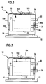
- the circulating pump 12 is, as shown in Figure 6, by means of a fixing device 92 on the article 14 to be cooled or heated fixed.
- the fixation device 92 includes one or more Retaining clips 94. With several retaining clips 94, these are spaced arranged.
Landscapes
- Engineering & Computer Science (AREA)
- General Engineering & Computer Science (AREA)
- Theoretical Computer Science (AREA)
- Physics & Mathematics (AREA)
- Mechanical Engineering (AREA)
- Human Computer Interaction (AREA)
- General Physics & Mathematics (AREA)
- Thermal Sciences (AREA)
- Structures Of Non-Positive Displacement Pumps (AREA)
- Cooling Or The Like Of Electrical Apparatus (AREA)
- Cooling Or The Like Of Semiconductors Or Solid State Devices (AREA)
Abstract
Description
Es zeigen:
- Figur 1
- eine seitliche (Teil-) Schnittansicht eines Ausführungsbeispiels einer erfindungsgemäßen Vorrichtung zur lokalen Kühlung oder Erwärmung eines Gegenstandes;
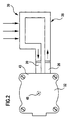
- Figur 2
- eine Draufsicht in der Richtung A auf die Vorrichtung gemäß Figur 1;
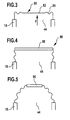
- Figur 3
- eine schematische Darstellung eines Ausführungsbeispiels eines thermischen Kontaktelements;
- Figur 4
- ein weiteres Ausführungsbeispiel eines thermischen Kontaktelements;
- Figur 5
- ein weiteres Ausführungsbeispiel eines thermischen Kontaktelements;
- Figur 6
- eine schematische Ansicht einer Fixierungsvorrichtung zur Fixierung einer Umwälzpumpe an dem Gegenstand, und
- Figur 7
- eine Variante des Ausführungsbeispiels gemäß Figur 5.
Claims (28)
- Vorrichtung zur lokalen Kühlung oder Erwärmung eines Gegenstandes (14) mittels einer Flüssigkeit, umfassend eine Umwälzpumpe (12) für die Flüssigkeit,
dadurch gekennzeichne t, daß ein thermisches Kontaktelement (32; 80; 86; 90) für die thermische Kontaktierung des Gegenstandes (14) in die Umwälzpumpe (12) integriert ist. - Vorrichtung nach Anspruch 1, dadurch gekennzeichnet, daß das thermische Kontaktelement (32; 80; 86; 90) Teil eines Gehäuses (18) der Umwälzpumpe (12) ist.
- Vorrichtung nach Anspruch 1 oder 2, dadurch gekennzeichnet, daß das thermische Kontaktelement (32) einen Gehäusedeckel der Umwälzpumpe (12) bildet.
- Vorrichtung nach einem der vorangehenden Ansprüche, dadurch gekennzeichnet, daß das thermische Kontaktelement (32; 80; 86; 90) einen Drallraum (44) der Umwälzpumpe (12) begrenzt.
- Vorrichtung nach Anspruch 4, dadurch gekennzeichnet, daß in dem Drallraum (44) ein Schaufelrad (46) rotierbar ist.
- Vorrichtung nach Anspruch 5, dadurch gekennzeichnet, daß die Umwälzpumpe (12) eine Deckplatte für das Schaufelrad (46) aufweist.
- Vorrichtung nach Anspruch 5 oder 6, dadurch gekennzeichnet, daß eine Durchsatzströmung, welche mittels des Schaufelrads (46) erzeugt ist, an dem thermischen Kontaktelement (32; 80; 86; 90) vorbeigeführt ist.
- Vorrichtung nach einem der Ansprüche 5 bis 7, dadurch gekennzeichnet, daß das Schaufelrad (46) dem thermischen Kontaktelement (32; 80; 86; 90) zugewandt angeordnet ist.
- Vorrichtung nach einem der vorangehenden Ansprüche, dadurch gekennzeichnet, daß das thermische Kontaktelement (32) aus einem metallischen Material hergestellt ist.
- Vorrichtung nach einem der vorangehenden Ansprüche, dadurch gekennzeichnet, daß das thermische Kontaktelement (32) als Platte ausgebildet ist.
- Vorrichtung nach einem der vorangehenden Ansprüche, dadurch gekennzeichnet, daß die Umwälzpumpe (12) als Kreiselpumpe ausgebildet ist.
- Vorrichtung nach Anspruch 11, dadurch gekennzeichnet, daß ein sphärisches Lager (58, 60) für einen Rotor (42) der Umwälzpumpe (12) vorgesehen ist.
- Vorrichtung nach Anspruch 11 oder 12, dadurch gekennzeichnet, daß die Umwälzpumpe (12) einen Elektromotor (38) umfaßt mit einem Stator (54) und einem Rotor (42), zwischen welchen ein sphärischer Luftspalt (74) gebildet ist.
- Vorrichtung nach einem der Ansprüche 11 bis 13, dadurch gekennzeichnet, daß die Umwälzpumpe (12) koaxial durchströmt ist.
- Vorrichtung nach einem der vorangehenden Ansprüche, dadurch gekennzeichnet, daß eine Zuführungsleitung (20) für flüssiges Medium quer zu einer Drehachse (40) eines Rotors (42) der Umwälzpumpe (12) an ein Gehäuse (18) der Umwälzpumpe (12) gekoppelt ist.
- Vorrichtung nach einem der vorangehenden Ansprüche, dadurch gekennzeichnet, daß eine Abführungsleitung (26) für flüssiges Medium quer zu einer Drehachse (40) eines Rotors (42) der Umwälzpumpe (12) an ein Gehäuse (18) der Umwälzpumpe (12) gekoppelt ist.
- Vorrichtung nach einem der vorangehenden Ansprüche, dadurch gekennzeichnet, daß eine Abführungsleitung (26) für flüssiges Medium von der Umwälzpumpe (12) und eine Zuführungsleitung (20) für flüssiges Medium zu der Umwälzpumpe (12) an der gleichen Seite (43) eines Gehäuses (18) der Umwälzpumpe (12) angekoppelt sind.
- Vorrichtung nach einem der vorangehenden Ansprüche, dadurch gekennzeichnet, daß das thermische Kontaktelement (32; 80; 86; 90) an der Druckseite der Umwälzpumpe (12) angeordnet ist.
- Vorrichtung nach einem der vorangehenden Ansprüche, dadurch gekennzeichnet, daß das thermische Kontaktelement (32; 80; 86; 90) auf seiner Innenseite (78) eine Verrippung aufweist.
- Vorrichtung nach Anspruch 19, dadurch gekennzeichnet, daß die Verrippung so ausgebildet ist, daß sie turbulenzfördernd ist.
- Vorrichtung nach einem der vorangehenden Ansprüche, dadurch gekennzeichnet, daß in einem Luftspalt (74) zwischen einem Stator (54) und einem Rotor (42) am Rotor (42) Schaufeln angeordnet sind.
- Vorrichtung nach einem der vorangehenden Ansprüche, dadurch gekennzeichnet, daß ein Drallraum (44) der Umwälzpumpe (12) ein variables Volumen aufweist.
- Vorrichtung nach einem der vorangehenden Ansprüche, dadurch gekennzeichnet, daß die Umwälzpumpe (12) ein Gehäuseteil (104; 80; 86) aufweist, welches derart flexibel ausgebildet und/oder beweglich ist, daß ein Vordruck auf das System ausübbar ist.
- Vorrichtung nach einem der vorangehenden Ansprüche, dadurch gekennzeichnet, daß die Umwälzpumpe (12) ein Gehäuseteil (104; 80; 86) aufweist, welches derart flexibel ausgebildet und/oder beweglich ist, daß ein Ausdehnungsvolumen für die Flüssigkeit bereitstellbar ist.
- Vorrichtung nach Anspruch 23 oder 24, dadurch gekennzeichnet, daß das flexible und/oder bewegliche Gehäuseteil (104) dem thermischen Kontaktelement (32) abgewandt am Gehäuse (18) angeordnet ist.
- Vorrichtung nach einem der vorangehenden Ansprüche, dadurch gekennzeichnet, daß das thermische Kontaktelement (80; 86; 90) flexibel ausgebildet ist und/oder beweglich an einem Gehäuse (18) der Umwälzpumpe (12) gelagert ist.
- Vorrichtung nach einem der Ansprüche 23 bis 26, dadurch gekennzeichnet, daß ein Vordruck auf das System mittels einer Fixierungsvorrichtung (92) für die Umwälzpumpe (12) an dem Gegenstand (14) ausübbar ist.
- Vorrichtung nach einem der vorangehenden Ansprüche, dadurch gekennzeichnet, daß die Umwälzpumpe (12) mittels einer oder mehrerer Halteklammern (94) bezüglich des Gegenstands (14) gehalten ist.
Applications Claiming Priority (2)
| Application Number | Priority Date | Filing Date | Title |
|---|---|---|---|
| DE10243026 | 2002-09-13 | ||
| DE10243026A DE10243026B3 (de) | 2002-09-13 | 2002-09-13 | Vorrichtung zur lokalen Kühlung oder Erwärmung eines Gegenstandes |
Publications (2)
| Publication Number | Publication Date |
|---|---|
| EP1398511A1 true EP1398511A1 (de) | 2004-03-17 |
| EP1398511B1 EP1398511B1 (de) | 2013-12-04 |
Family
ID=31724819
Family Applications (1)
| Application Number | Title | Priority Date | Filing Date |
|---|---|---|---|
| EP03019804.8A Expired - Lifetime EP1398511B1 (de) | 2002-09-13 | 2003-08-30 | Vorrichtung zur lokalen Kühlung oder Erwärmung eines Gegenstandes |
Country Status (4)
| Country | Link |
|---|---|
| US (2) | US20040052663A1 (de) |
| EP (1) | EP1398511B1 (de) |
| JP (1) | JP4808370B2 (de) |
| DE (1) | DE10243026B3 (de) |
Cited By (6)
| Publication number | Priority date | Publication date | Assignee | Title |
|---|---|---|---|---|
| WO2006021358A1 (de) | 2004-08-26 | 2006-03-02 | Oliver Laing | Energieversorgungsvorrichtung für ein elektrisches gerät und verfahren zur bereitstellung elektrischer energie an komponenten eines elektrischen geräts |
| DE102004043398A1 (de) * | 2004-09-03 | 2006-06-22 | Laing, Oliver | Kühlungsanordnung für ein elektrisches Gerät und Verfahren zur Flüssigkeitskühlung |
| WO2007002876A1 (en) * | 2005-06-29 | 2007-01-04 | Intel Corporation | Systems for integrated pump and reservoir |
| CN100408863C (zh) * | 2005-08-18 | 2008-08-06 | 建凖电机工业股份有限公司 | 水泵 |
| EP3176438A1 (de) * | 2015-12-03 | 2017-06-07 | Grundfos Holding A/S | Pumpenaggregat |
| CN115853788A (zh) * | 2023-01-04 | 2023-03-28 | 晋江爱家制冷设备有限公司 | 一种一体式的屏蔽泵 |
Families Citing this family (51)
| Publication number | Priority date | Publication date | Assignee | Title |
|---|---|---|---|---|
| US6881039B2 (en) * | 2002-09-23 | 2005-04-19 | Cooligy, Inc. | Micro-fabricated electrokinetic pump |
| JP2006522463A (ja) * | 2002-11-01 | 2006-09-28 | クーリギー インコーポレイテッド | 流体により冷却される超小型熱交換のための最適なスプレッダシステム、装置及び方法 |
| US8464781B2 (en) * | 2002-11-01 | 2013-06-18 | Cooligy Inc. | Cooling systems incorporating heat exchangers and thermoelectric layers |
| US20050211418A1 (en) * | 2002-11-01 | 2005-09-29 | Cooligy, Inc. | Method and apparatus for efficient vertical fluid delivery for cooling a heat producing device |
| US7836597B2 (en) | 2002-11-01 | 2010-11-23 | Cooligy Inc. | Method of fabricating high surface to volume ratio structures and their integration in microheat exchangers for liquid cooling system |
| US7044196B2 (en) * | 2003-01-31 | 2006-05-16 | Cooligy,Inc | Decoupled spring-loaded mounting apparatus and method of manufacturing thereof |
| US7201012B2 (en) * | 2003-01-31 | 2007-04-10 | Cooligy, Inc. | Remedies to prevent cracking in a liquid system |
| US20040233639A1 (en) * | 2003-01-31 | 2004-11-25 | Cooligy, Inc. | Removeable heat spreader support mechanism and method of manufacturing thereof |
| US20040182551A1 (en) * | 2003-03-17 | 2004-09-23 | Cooligy, Inc. | Boiling temperature design in pumped microchannel cooling loops |
| JP4244703B2 (ja) * | 2003-05-26 | 2009-03-25 | パナソニック株式会社 | 冷却装置 |
| WO2004107837A1 (ja) * | 2003-05-30 | 2004-12-09 | Matsushita Electric Industrial Co., Ltd. | 冷却装置 |
| US7591302B1 (en) * | 2003-07-23 | 2009-09-22 | Cooligy Inc. | Pump and fan control concepts in a cooling system |
| DK1923771T3 (en) | 2003-11-07 | 2015-06-01 | Asetek As | Cooling system for a computer system |
| US20050269691A1 (en) * | 2004-06-04 | 2005-12-08 | Cooligy, Inc. | Counter flow micro heat exchanger for optimal performance |
| WO2006021359A1 (de) * | 2004-08-26 | 2006-03-02 | Laing, Oliver | Kühlungsanordnung für eine elektrisches gerät und verfahren zur flüssigkeitskühlung |
| JP4653444B2 (ja) * | 2004-08-30 | 2011-03-16 | 株式会社東芝 | 冷却用流体ポンプ、冷却装置及び電気機器 |
| US7267532B2 (en) * | 2004-12-28 | 2007-09-11 | Micropump, Inc., A Unit Of Idex Corporation | Offset-drive magnetically driven gear-pump heads and gear pumps comprising same |
| US7143820B2 (en) * | 2004-12-31 | 2006-12-05 | Intel Corporation | Systems for improved heat exchanger |
| US20090218072A1 (en) | 2005-05-06 | 2009-09-03 | Andre Sloth Eriksen | Cooling system for a computer system |
| US7262967B2 (en) * | 2005-06-29 | 2007-08-28 | Intel Corporation | Systems for low cost coaxial liquid cooling |
| TWI272056B (en) * | 2005-08-12 | 2007-01-21 | Foxconn Tech Co Ltd | Integrated liquid cooling system |
| US7331380B2 (en) * | 2005-08-17 | 2008-02-19 | Delphi Technologies, Inc. | Radial flow micro-channel heat sink with impingement cooling |
| US20070114010A1 (en) * | 2005-11-09 | 2007-05-24 | Girish Upadhya | Liquid cooling for backlit displays |
| US20070175621A1 (en) * | 2006-01-31 | 2007-08-02 | Cooligy, Inc. | Re-workable metallic TIM for efficient heat exchange |
| EP1989935A4 (de) * | 2006-02-16 | 2012-07-04 | Cooligy Inc | Flüssigkeitskühlungsschleifen für serveranwendungen |
| US20070227698A1 (en) * | 2006-03-30 | 2007-10-04 | Conway Bruce R | Integrated fluid pump and radiator reservoir |
| TW200809477A (en) | 2006-03-30 | 2008-02-16 | Cooligy Inc | Integrated fluid pump and radiator reservoir |
| US7404433B1 (en) * | 2007-01-31 | 2008-07-29 | Man Zai Industrial Co., Ltd. | Liquid cooled heat sink |
| US9453691B2 (en) | 2007-08-09 | 2016-09-27 | Coolit Systems, Inc. | Fluid heat exchange systems |
| US8746330B2 (en) | 2007-08-09 | 2014-06-10 | Coolit Systems Inc. | Fluid heat exchanger configured to provide a split flow |
| US7688589B2 (en) * | 2007-11-01 | 2010-03-30 | Asia Vital Components Co., Ltd. | Water cooled heat dissipation module for electronic device |
| JP4849114B2 (ja) * | 2008-10-16 | 2012-01-11 | パナソニック株式会社 | 冷却装置 |
| US20120007452A1 (en) * | 2010-07-06 | 2012-01-12 | Bingler Douglas J | Encapsulated stator spherical rotor motor pump |
| CZ2015399A3 (cs) | 2015-06-15 | 2017-02-08 | Jiří Dostál | Zapojení systému pro řízení výkonu a diagnostiku tepelného výměníku |
| CN205105503U (zh) * | 2015-10-12 | 2016-03-23 | 酷码科技股份有限公司 | 散热模块、散热系统以及电路模块 |
| DE102016220641A1 (de) * | 2016-10-20 | 2018-04-26 | Continental Automotive Gmbh | Kraftstoffpumpe |
| JP6518275B2 (ja) | 2017-02-24 | 2019-05-22 | シナノケンシ株式会社 | 電動ポンプ |
| US20190041104A1 (en) * | 2017-08-07 | 2019-02-07 | Asia Vital Components Co., Ltd. | Heat exchange structure of heat dissipation device |
| CZ308007B6 (cs) | 2018-05-14 | 2019-10-16 | ÄŚeskĂ© vysokĂ© uÄŤenĂ technickĂ© v Praze | Zařízení pro řízení výkonu tepelného výměníku v jednopotrubní otopné síti |
| TWI733134B (zh) * | 2018-07-09 | 2021-07-11 | 雙鴻科技股份有限公司 | 水冷頭 |
| US11800679B2 (en) * | 2019-01-31 | 2023-10-24 | Shenzhen APALTEK Co., Ltd. | Integrated water cooling heat sink |
| BR112021017150A2 (pt) * | 2019-03-01 | 2021-11-09 | Vapotherm Inc | Rotores para uso em meios cáusticos |
| JP2020180579A (ja) * | 2019-04-25 | 2020-11-05 | 株式会社鷺宮製作所 | 遠心ポンプ、および、遠心ポンプを用いた冷却システム |
| CN213960586U (zh) * | 2020-06-12 | 2021-08-13 | 春鸿电子科技(重庆)有限公司 | 水冷头 |
| US11725886B2 (en) | 2021-05-20 | 2023-08-15 | Coolit Systems, Inc. | Modular fluid heat exchange systems |
| CN217523124U (zh) * | 2021-10-08 | 2022-09-30 | 春鸿电子科技(重庆)有限公司 | 水冷头 |
| TWM636825U (zh) * | 2022-08-31 | 2023-01-21 | 訊凱國際股份有限公司 | 液流式散熱裝置 |
| EP4581672A1 (de) * | 2022-09-02 | 2025-07-09 | City St George's, University of London | Pumpe |
| GB202212766D0 (en) * | 2022-09-02 | 2022-10-19 | City Univ Of London | Pump |
| DE102023203115A1 (de) | 2023-04-04 | 2024-10-10 | Vitesco Technologies GmbH | Thermoelastisches Energiewandlersystem |
| TWI884086B (zh) * | 2024-09-18 | 2025-05-11 | 冠鼎科技股份有限公司 | 液冷式散熱裝置 |
Citations (6)
| Publication number | Priority date | Publication date | Assignee | Title |
|---|---|---|---|---|
| DE3538504C2 (de) | 1984-11-02 | 1995-04-27 | Laing Karsten | Koaxial durchströmte Kreiselpumpe |
| US6019165A (en) * | 1998-05-18 | 2000-02-01 | Batchelder; John Samuel | Heat exchange apparatus |
| US6132184A (en) * | 1998-11-05 | 2000-10-17 | Ford Motor Company | Reservoir apparatus for an electronically controlled electric pump |
| EP1085217A2 (de) * | 1999-09-13 | 2001-03-21 | WILO GmbH | Pumpengehäuse mit intergrierter Elektronik |
| US6327145B1 (en) * | 2000-09-01 | 2001-12-04 | Intel Corporation | Heat sink with integrated fluid circulation pump |
| WO2003098415A1 (en) * | 2002-05-15 | 2003-11-27 | Matsushita Electric Industrial Co., Ltd. | A liquid cooling device for a notebook computer |
Family Cites Families (21)
| Publication number | Priority date | Publication date | Assignee | Title |
|---|---|---|---|---|
| AT335563B (de) * | 1975-01-13 | 1977-03-25 | Vortex Gmbh Dt | Pumpen-motor-einheit |
| US4728268A (en) * | 1984-11-02 | 1988-03-01 | Karsten Laing | Rotodynamic pump |
| JPS61220359A (ja) * | 1985-03-26 | 1986-09-30 | Hitachi Ltd | 半導体モジユ−ル冷却構造体 |
| JPS62282452A (ja) * | 1986-01-28 | 1987-12-08 | Fujitsu Ltd | 集積回路冷却装置 |
| US5195020A (en) * | 1987-05-25 | 1993-03-16 | Fujitsu Limited | Cooling system used with an electronic circuit device for cooling circuit components included therein having a thermally conductive compound layer and method for forming the layer |
| EP0293297B1 (de) * | 1987-05-25 | 1995-01-25 | Fujitsu Limited | Kühlungssystem für Festkörperschaltungsbauelemente und ein Verfahren zum Versehen mit thermoleitenden Zusammensetzungen |
| US4874300A (en) * | 1987-12-21 | 1989-10-17 | Laing Karsten A | Ceramic step bearing in a centrifugal pump |
| JPH0734230Y2 (ja) * | 1989-06-22 | 1995-08-02 | 株式会社荏原製作所 | マグネットポンプの冷却装置 |
| US5049982A (en) * | 1989-07-28 | 1991-09-17 | At&T Bell Laboratories | Article comprising a stacked array of electronic subassemblies |
| DE4220077A1 (de) * | 1992-06-19 | 1993-12-23 | Bosch Gmbh Robert | Mikropumpe |
| JPH06266474A (ja) * | 1993-03-17 | 1994-09-22 | Hitachi Ltd | 電子機器装置及びラップトップ型電子機器装置 |
| JPH09112479A (ja) * | 1995-10-16 | 1997-05-02 | Kubota Corp | 球体ポンプ |
| US5731954A (en) * | 1996-08-22 | 1998-03-24 | Cheon; Kioan | Cooling system for computer |
| JPH10196587A (ja) * | 1997-01-13 | 1998-07-31 | Toshiba Corp | 偏平型モータ組込み型ポンプ |
| US6152213A (en) * | 1997-03-27 | 2000-11-28 | Fujitsu Limited | Cooling system for electronic packages |
| JPH11166500A (ja) * | 1997-12-03 | 1999-06-22 | Toshiba Ave Co Ltd | ポンプ |
| US6074092A (en) * | 1998-09-28 | 2000-06-13 | Varian Medical Systems, Inc. | Cooling system for an x-ray source |
| JP2001320187A (ja) * | 2000-02-29 | 2001-11-16 | Matsushita Electric Ind Co Ltd | 電子部品の液体冷却装置 |
| US6408937B1 (en) * | 2000-11-15 | 2002-06-25 | Sanjay K. Roy | Active cold plate/heat sink |
| US6668911B2 (en) * | 2002-05-08 | 2003-12-30 | Itt Manufacturing Enterprises, Inc. | Pump system for use in a heat exchange application |
| US6986640B2 (en) * | 2002-05-20 | 2006-01-17 | Oliver Laing | Motor pump with expansion tank |
-
2002
- 2002-09-13 DE DE10243026A patent/DE10243026B3/de not_active Expired - Fee Related
-
2003
- 2003-05-07 US US10/434,307 patent/US20040052663A1/en not_active Abandoned
- 2003-08-30 EP EP03019804.8A patent/EP1398511B1/de not_active Expired - Lifetime
- 2003-09-11 JP JP2003319266A patent/JP4808370B2/ja not_active Expired - Fee Related
-
2007
- 2007-01-16 US US11/653,463 patent/US7648347B2/en not_active Expired - Fee Related
Patent Citations (6)
| Publication number | Priority date | Publication date | Assignee | Title |
|---|---|---|---|---|
| DE3538504C2 (de) | 1984-11-02 | 1995-04-27 | Laing Karsten | Koaxial durchströmte Kreiselpumpe |
| US6019165A (en) * | 1998-05-18 | 2000-02-01 | Batchelder; John Samuel | Heat exchange apparatus |
| US6132184A (en) * | 1998-11-05 | 2000-10-17 | Ford Motor Company | Reservoir apparatus for an electronically controlled electric pump |
| EP1085217A2 (de) * | 1999-09-13 | 2001-03-21 | WILO GmbH | Pumpengehäuse mit intergrierter Elektronik |
| US6327145B1 (en) * | 2000-09-01 | 2001-12-04 | Intel Corporation | Heat sink with integrated fluid circulation pump |
| WO2003098415A1 (en) * | 2002-05-15 | 2003-11-27 | Matsushita Electric Industrial Co., Ltd. | A liquid cooling device for a notebook computer |
Cited By (9)
| Publication number | Priority date | Publication date | Assignee | Title |
|---|---|---|---|---|
| WO2006021358A1 (de) | 2004-08-26 | 2006-03-02 | Oliver Laing | Energieversorgungsvorrichtung für ein elektrisches gerät und verfahren zur bereitstellung elektrischer energie an komponenten eines elektrischen geräts |
| DE102004042034A1 (de) * | 2004-08-26 | 2006-03-16 | Laing, Oliver | Energieversorgungsvorrichtung für ein elektrisches Gerät und Verfahren zur Bereitstellung elektrischer Energie an Komponenten eines elektrischen Geräts |
| US7660120B2 (en) | 2004-08-26 | 2010-02-09 | Itt Manufacturing Enterprises, Inc. | Power supply unit for an electrical appliance and method for making electrical power available at components of an electrical appliance |
| DE102004043398A1 (de) * | 2004-09-03 | 2006-06-22 | Laing, Oliver | Kühlungsanordnung für ein elektrisches Gerät und Verfahren zur Flüssigkeitskühlung |
| WO2007002876A1 (en) * | 2005-06-29 | 2007-01-04 | Intel Corporation | Systems for integrated pump and reservoir |
| US7543457B2 (en) | 2005-06-29 | 2009-06-09 | Intel Corporation | Systems for integrated pump and reservoir |
| CN100408863C (zh) * | 2005-08-18 | 2008-08-06 | 建凖电机工业股份有限公司 | 水泵 |
| EP3176438A1 (de) * | 2015-12-03 | 2017-06-07 | Grundfos Holding A/S | Pumpenaggregat |
| CN115853788A (zh) * | 2023-01-04 | 2023-03-28 | 晋江爱家制冷设备有限公司 | 一种一体式的屏蔽泵 |
Also Published As
| Publication number | Publication date |
|---|---|
| DE10243026B3 (de) | 2004-06-03 |
| JP2004183646A (ja) | 2004-07-02 |
| US7648347B2 (en) | 2010-01-19 |
| JP4808370B2 (ja) | 2011-11-02 |
| US20070115634A1 (en) | 2007-05-24 |
| US20040052663A1 (en) | 2004-03-18 |
| EP1398511B1 (de) | 2013-12-04 |
Similar Documents
| Publication | Publication Date | Title |
|---|---|---|
| EP1398511B1 (de) | Vorrichtung zur lokalen Kühlung oder Erwärmung eines Gegenstandes | |
| DE10209097B4 (de) | Motorbetriebenes Werkzeug | |
| EP1565905B1 (de) | Verfahren und vorrichtung zur kühlung von ultraschallwandlern | |
| EP2566015B1 (de) | Elektromotor | |
| WO2002052205A2 (de) | Kompressor | |
| EP1703140A1 (de) | Kühleinrichtung für ein elektromotorisch angetriebenes Radialgebläse | |
| EP2615299A1 (de) | Turmkopf einer Windenergieanlage | |
| DE102005041538A1 (de) | Gantry eines Computertomographen | |
| WO2019052922A1 (de) | Lidar-anordnung mit strömungskühlung | |
| EP1961281B1 (de) | Gerät, baureihe von geräten, vorrichtung mit gehäuseteilen, verfahren, verwendung eines luftkühlers und verwendung eines flüssigkeitskühlers | |
| DE3603423C2 (de) | ||
| DE102024117423A1 (de) | Integrierte flüssigkeitskühlvorrichtung mit zwei flüssigkeitspumpen und zwei kreisläufen | |
| DE102005007545B4 (de) | Vorrichtung und Verfahren zur Kühlung einer Elektronik | |
| EP3940239A1 (de) | Strömungsmaschine mit kühlkanal | |
| DE10306227B4 (de) | Leistungsmodul und Umrichter | |
| EP1226644A1 (de) | Elektrischer antrieb | |
| EP3593078B1 (de) | Kühlvorrichtung | |
| DE2744918C2 (de) | Kühlvorrichtung für Maschinenteile, insbesondere Wellen und Wellenlager | |
| DE1491077A1 (de) | Elektro-Kleinstmotor | |
| EP4396014A1 (de) | Kühlmittelverteilervorrichtung für ein kraftfahrzeug und kraftfahrzeug mit einer kühlmittelverteilervorrichtung | |
| EP0665379A1 (de) | Pumpenträger mit integriertem Ölkühler | |
| WO2012055402A1 (de) | Cpu-kühler | |
| EP0803418A1 (de) | Antriebseinheit mit einem Motor und einem Retarder | |
| DE20305281U1 (de) | Temperiervorrichtung zum Temperieren, insbesondere zum Kühlen eines elektronischen Bauteils, mit einer Temperierflüssigkeit | |
| DE102022123882B4 (de) | Vorrichtung zum Leiten von Kühlluft an einer Motoraufnahme für einen Ventilatormotor |
Legal Events
| Date | Code | Title | Description |
|---|---|---|---|
| PUAI | Public reference made under article 153(3) epc to a published international application that has entered the european phase |
Free format text: ORIGINAL CODE: 0009012 |
|
| AK | Designated contracting states |
Kind code of ref document: A1 Designated state(s): AT BE BG CH CY CZ DE DK EE ES FI FR GB GR HU IE IT LI LU MC NL PT RO SE SI SK TR |
|
| AX | Request for extension of the european patent |
Extension state: AL LT LV MK |
|
| 17P | Request for examination filed |
Effective date: 20040820 |
|
| AKX | Designation fees paid |
Designated state(s): AT BE BG CH CY CZ DE DK EE ES FI FR GB GR HU IE IT LI LU MC NL PT RO SE SI SK TR |
|
| 17Q | First examination report despatched |
Effective date: 20070207 |
|
| RAP1 | Party data changed (applicant data changed or rights of an application transferred) |
Owner name: ITT MANUFACTURING ENTERPRISES, INC. |
|
| GRAP | Despatch of communication of intention to grant a patent |
Free format text: ORIGINAL CODE: EPIDOSNIGR1 |
|
| RAP1 | Party data changed (applicant data changed or rights of an application transferred) |
Owner name: XYLEM IP HOLDINGS LLC |
|
| INTG | Intention to grant announced |
Effective date: 20130513 |
|
| GRAS | Grant fee paid |
Free format text: ORIGINAL CODE: EPIDOSNIGR3 |
|
| GRAA | (expected) grant |
Free format text: ORIGINAL CODE: 0009210 |
|
| AK | Designated contracting states |
Kind code of ref document: B1 Designated state(s): AT BE BG CH CY CZ DE DK EE ES FI FR GB GR HU IE IT LI LU MC NL PT RO SE SI SK TR |
|
| REG | Reference to a national code |
Ref country code: GB Ref legal event code: FG4D Free format text: NOT ENGLISH |
|
| REG | Reference to a national code |
Ref country code: CH Ref legal event code: EP |
|
| REG | Reference to a national code |
Ref country code: AT Ref legal event code: REF Ref document number: 643660 Country of ref document: AT Kind code of ref document: T Effective date: 20140115 Ref country code: IE Ref legal event code: FG4D Free format text: LANGUAGE OF EP DOCUMENT: GERMAN |
|
| REG | Reference to a national code |
Ref country code: DE Ref legal event code: R096 Ref document number: 50314951 Country of ref document: DE Effective date: 20140130 |
|
| REG | Reference to a national code |
Ref country code: NL Ref legal event code: VDEP Effective date: 20131204 |
|
| PG25 | Lapsed in a contracting state [announced via postgrant information from national office to epo] |
Ref country code: SE Free format text: LAPSE BECAUSE OF FAILURE TO SUBMIT A TRANSLATION OF THE DESCRIPTION OR TO PAY THE FEE WITHIN THE PRESCRIBED TIME-LIMIT Effective date: 20131204 Ref country code: FI Free format text: LAPSE BECAUSE OF FAILURE TO SUBMIT A TRANSLATION OF THE DESCRIPTION OR TO PAY THE FEE WITHIN THE PRESCRIBED TIME-LIMIT Effective date: 20131204 Ref country code: NL Free format text: LAPSE BECAUSE OF FAILURE TO SUBMIT A TRANSLATION OF THE DESCRIPTION OR TO PAY THE FEE WITHIN THE PRESCRIBED TIME-LIMIT Effective date: 20131204 |
|
| PG25 | Lapsed in a contracting state [announced via postgrant information from national office to epo] |
Ref country code: CY Free format text: LAPSE BECAUSE OF FAILURE TO SUBMIT A TRANSLATION OF THE DESCRIPTION OR TO PAY THE FEE WITHIN THE PRESCRIBED TIME-LIMIT Effective date: 20131204 |
|
| PG25 | Lapsed in a contracting state [announced via postgrant information from national office to epo] |
Ref country code: EE Free format text: LAPSE BECAUSE OF FAILURE TO SUBMIT A TRANSLATION OF THE DESCRIPTION OR TO PAY THE FEE WITHIN THE PRESCRIBED TIME-LIMIT Effective date: 20131204 |
|
| PG25 | Lapsed in a contracting state [announced via postgrant information from national office to epo] |
Ref country code: RO Free format text: LAPSE BECAUSE OF FAILURE TO SUBMIT A TRANSLATION OF THE DESCRIPTION OR TO PAY THE FEE WITHIN THE PRESCRIBED TIME-LIMIT Effective date: 20131204 Ref country code: PT Free format text: LAPSE BECAUSE OF FAILURE TO SUBMIT A TRANSLATION OF THE DESCRIPTION OR TO PAY THE FEE WITHIN THE PRESCRIBED TIME-LIMIT Effective date: 20140404 Ref country code: SK Free format text: LAPSE BECAUSE OF FAILURE TO SUBMIT A TRANSLATION OF THE DESCRIPTION OR TO PAY THE FEE WITHIN THE PRESCRIBED TIME-LIMIT Effective date: 20131204 Ref country code: CZ Free format text: LAPSE BECAUSE OF FAILURE TO SUBMIT A TRANSLATION OF THE DESCRIPTION OR TO PAY THE FEE WITHIN THE PRESCRIBED TIME-LIMIT Effective date: 20131204 Ref country code: ES Free format text: LAPSE BECAUSE OF FAILURE TO SUBMIT A TRANSLATION OF THE DESCRIPTION OR TO PAY THE FEE WITHIN THE PRESCRIBED TIME-LIMIT Effective date: 20131204 |
|
| REG | Reference to a national code |
Ref country code: DE Ref legal event code: R097 Ref document number: 50314951 Country of ref document: DE |
|
| PLBE | No opposition filed within time limit |
Free format text: ORIGINAL CODE: 0009261 |
|
| STAA | Information on the status of an ep patent application or granted ep patent |
Free format text: STATUS: NO OPPOSITION FILED WITHIN TIME LIMIT |
|
| PG25 | Lapsed in a contracting state [announced via postgrant information from national office to epo] |
Ref country code: DK Free format text: LAPSE BECAUSE OF FAILURE TO SUBMIT A TRANSLATION OF THE DESCRIPTION OR TO PAY THE FEE WITHIN THE PRESCRIBED TIME-LIMIT Effective date: 20131204 |
|
| 26N | No opposition filed |
Effective date: 20140905 |
|
| REG | Reference to a national code |
Ref country code: DE Ref legal event code: R097 Ref document number: 50314951 Country of ref document: DE Effective date: 20140905 |
|
| PG25 | Lapsed in a contracting state [announced via postgrant information from national office to epo] |
Ref country code: SI Free format text: LAPSE BECAUSE OF FAILURE TO SUBMIT A TRANSLATION OF THE DESCRIPTION OR TO PAY THE FEE WITHIN THE PRESCRIBED TIME-LIMIT Effective date: 20131204 |
|
| PG25 | Lapsed in a contracting state [announced via postgrant information from national office to epo] |
Ref country code: LU Free format text: LAPSE BECAUSE OF FAILURE TO SUBMIT A TRANSLATION OF THE DESCRIPTION OR TO PAY THE FEE WITHIN THE PRESCRIBED TIME-LIMIT Effective date: 20140830 Ref country code: MC Free format text: LAPSE BECAUSE OF FAILURE TO SUBMIT A TRANSLATION OF THE DESCRIPTION OR TO PAY THE FEE WITHIN THE PRESCRIBED TIME-LIMIT Effective date: 20131204 |
|
| REG | Reference to a national code |
Ref country code: CH Ref legal event code: PL |
|
| PG25 | Lapsed in a contracting state [announced via postgrant information from national office to epo] |
Ref country code: LI Free format text: LAPSE BECAUSE OF NON-PAYMENT OF DUE FEES Effective date: 20140831 Ref country code: CH Free format text: LAPSE BECAUSE OF NON-PAYMENT OF DUE FEES Effective date: 20140831 Ref country code: BE Free format text: LAPSE BECAUSE OF NON-PAYMENT OF DUE FEES Effective date: 20140831 |
|
| REG | Reference to a national code |
Ref country code: IE Ref legal event code: MM4A |
|
| REG | Reference to a national code |
Ref country code: DE Ref legal event code: R082 Ref document number: 50314951 Country of ref document: DE Representative=s name: HOEGER, STELLRECHT & PARTNER PATENTANWAELTE MB, DE Ref country code: DE Ref legal event code: R082 Ref document number: 50314951 Country of ref document: DE Representative=s name: LENZING GERBER STUTE PARTNERSCHAFTSGESELLSCHAF, DE |
|
| REG | Reference to a national code |
Ref country code: FR Ref legal event code: PLFP Year of fee payment: 13 |
|
| PG25 | Lapsed in a contracting state [announced via postgrant information from national office to epo] |
Ref country code: IE Free format text: LAPSE BECAUSE OF NON-PAYMENT OF DUE FEES Effective date: 20140830 |
|
| REG | Reference to a national code |
Ref country code: AT Ref legal event code: MM01 Ref document number: 643660 Country of ref document: AT Kind code of ref document: T Effective date: 20140830 |
|
| PG25 | Lapsed in a contracting state [announced via postgrant information from national office to epo] |
Ref country code: AT Free format text: LAPSE BECAUSE OF NON-PAYMENT OF DUE FEES Effective date: 20140830 |
|
| PG25 | Lapsed in a contracting state [announced via postgrant information from national office to epo] |
Ref country code: BG Free format text: LAPSE BECAUSE OF FAILURE TO SUBMIT A TRANSLATION OF THE DESCRIPTION OR TO PAY THE FEE WITHIN THE PRESCRIBED TIME-LIMIT Effective date: 20131204 |
|
| PG25 | Lapsed in a contracting state [announced via postgrant information from national office to epo] |
Ref country code: GR Free format text: LAPSE BECAUSE OF FAILURE TO SUBMIT A TRANSLATION OF THE DESCRIPTION OR TO PAY THE FEE WITHIN THE PRESCRIBED TIME-LIMIT Effective date: 20140305 |
|
| PG25 | Lapsed in a contracting state [announced via postgrant information from national office to epo] |
Ref country code: HU Free format text: LAPSE BECAUSE OF FAILURE TO SUBMIT A TRANSLATION OF THE DESCRIPTION OR TO PAY THE FEE WITHIN THE PRESCRIBED TIME-LIMIT; INVALID AB INITIO Effective date: 20030830 Ref country code: TR Free format text: LAPSE BECAUSE OF FAILURE TO SUBMIT A TRANSLATION OF THE DESCRIPTION OR TO PAY THE FEE WITHIN THE PRESCRIBED TIME-LIMIT Effective date: 20131204 |
|
| REG | Reference to a national code |
Ref country code: FR Ref legal event code: PLFP Year of fee payment: 14 |
|
| REG | Reference to a national code |
Ref country code: DE Ref legal event code: R082 Ref document number: 50314951 Country of ref document: DE Representative=s name: LENZING GERBER STUTE PARTNERSCHAFTSGESELLSCHAF, DE |
|
| REG | Reference to a national code |
Ref country code: FR Ref legal event code: PLFP Year of fee payment: 15 |
|
| REG | Reference to a national code |
Ref country code: FR Ref legal event code: PLFP Year of fee payment: 16 |
|
| PGFP | Annual fee paid to national office [announced via postgrant information from national office to epo] |
Ref country code: FR Payment date: 20200825 Year of fee payment: 18 Ref country code: GB Payment date: 20200827 Year of fee payment: 18 Ref country code: DE Payment date: 20200827 Year of fee payment: 18 |
|
| PGFP | Annual fee paid to national office [announced via postgrant information from national office to epo] |
Ref country code: IT Payment date: 20200821 Year of fee payment: 18 |
|
| REG | Reference to a national code |
Ref country code: DE Ref legal event code: R119 Ref document number: 50314951 Country of ref document: DE |
|
| GBPC | Gb: european patent ceased through non-payment of renewal fee |
Effective date: 20210830 |
|
| PG25 | Lapsed in a contracting state [announced via postgrant information from national office to epo] |
Ref country code: IT Free format text: LAPSE BECAUSE OF NON-PAYMENT OF DUE FEES Effective date: 20210830 Ref country code: GB Free format text: LAPSE BECAUSE OF NON-PAYMENT OF DUE FEES Effective date: 20210830 Ref country code: FR Free format text: LAPSE BECAUSE OF NON-PAYMENT OF DUE FEES Effective date: 20210831 Ref country code: DE Free format text: LAPSE BECAUSE OF NON-PAYMENT OF DUE FEES Effective date: 20220301 |