EP1394785B1 - Method and apparatus for correcting tilt of light beam to optical recording medium - Google Patents
Method and apparatus for correcting tilt of light beam to optical recording medium Download PDFInfo
- Publication number
- EP1394785B1 EP1394785B1 EP03019516A EP03019516A EP1394785B1 EP 1394785 B1 EP1394785 B1 EP 1394785B1 EP 03019516 A EP03019516 A EP 03019516A EP 03019516 A EP03019516 A EP 03019516A EP 1394785 B1 EP1394785 B1 EP 1394785B1
- Authority
- EP
- European Patent Office
- Prior art keywords
- tilt
- amount
- correcting
- disk
- signal
- Prior art date
- Legal status (The legal status is an assumption and is not a legal conclusion. Google has not performed a legal analysis and makes no representation as to the accuracy of the status listed.)
- Expired - Lifetime
Links
- 238000000034 method Methods 0.000 title claims description 15
- 230000003287 optical effect Effects 0.000 title description 20
- 238000012937 correction Methods 0.000 claims description 72
- 230000015654 memory Effects 0.000 claims description 7
- 208000011738 Lichen planopilaris Diseases 0.000 description 98
- 208000011797 pustulosis palmaris et plantaris Diseases 0.000 description 98
- 238000012545 processing Methods 0.000 description 34
- 238000001514 detection method Methods 0.000 description 29
- 238000005259 measurement Methods 0.000 description 19
- 238000004519 manufacturing process Methods 0.000 description 12
- 230000007246 mechanism Effects 0.000 description 7
- 239000004973 liquid crystal related substance Substances 0.000 description 4
- 238000004364 calculation method Methods 0.000 description 3
- 238000010586 diagram Methods 0.000 description 3
- 230000006870 function Effects 0.000 description 2
- 238000012986 modification Methods 0.000 description 2
- 230000004048 modification Effects 0.000 description 2
- 230000032683 aging Effects 0.000 description 1
- 238000006243 chemical reaction Methods 0.000 description 1
- 239000000470 constituent Substances 0.000 description 1
- 230000001678 irradiating effect Effects 0.000 description 1
- 239000012528 membrane Substances 0.000 description 1
- 238000012544 monitoring process Methods 0.000 description 1
- 238000012887 quadratic function Methods 0.000 description 1
- 230000009467 reduction Effects 0.000 description 1
- 230000004044 response Effects 0.000 description 1
- 238000004904 shortening Methods 0.000 description 1
- 239000000758 substrate Substances 0.000 description 1
Images


Classifications
-
- G—PHYSICS
- G11—INFORMATION STORAGE
- G11B—INFORMATION STORAGE BASED ON RELATIVE MOVEMENT BETWEEN RECORD CARRIER AND TRANSDUCER
- G11B7/00—Recording or reproducing by optical means, e.g. recording using a thermal beam of optical radiation by modifying optical properties or the physical structure, reproducing using an optical beam at lower power by sensing optical properties; Record carriers therefor
- G11B7/08—Disposition or mounting of heads or light sources relatively to record carriers
- G11B7/09—Disposition or mounting of heads or light sources relatively to record carriers with provision for moving the light beam or focus plane for the purpose of maintaining alignment of the light beam relative to the record carrier during transducing operation, e.g. to compensate for surface irregularities of the latter or for track following
- G11B7/095—Disposition or mounting of heads or light sources relatively to record carriers with provision for moving the light beam or focus plane for the purpose of maintaining alignment of the light beam relative to the record carrier during transducing operation, e.g. to compensate for surface irregularities of the latter or for track following specially adapted for discs, e.g. for compensation of eccentricity or wobble
- G11B7/0956—Disposition or mounting of heads or light sources relatively to record carriers with provision for moving the light beam or focus plane for the purpose of maintaining alignment of the light beam relative to the record carrier during transducing operation, e.g. to compensate for surface irregularities of the latter or for track following specially adapted for discs, e.g. for compensation of eccentricity or wobble to compensate for tilt, skew, warp or inclination of the disc, i.e. maintain the optical axis at right angles to the disc
-
- G—PHYSICS
- G11—INFORMATION STORAGE
- G11B—INFORMATION STORAGE BASED ON RELATIVE MOVEMENT BETWEEN RECORD CARRIER AND TRANSDUCER
- G11B7/00—Recording or reproducing by optical means, e.g. recording using a thermal beam of optical radiation by modifying optical properties or the physical structure, reproducing using an optical beam at lower power by sensing optical properties; Record carriers therefor
- G11B7/004—Recording, reproducing or erasing methods; Read, write or erase circuits therefor
- G11B7/005—Reproducing
- G11B7/0053—Reproducing non-user data, e.g. wobbled address, prepits, BCA
Definitions
- the present invention relates to a method and apparatus for correcting the tilt of a light beam to optical recording mediums such as optical disks.
- the tilt correction is to correct a tilt of an optical beam (also known as "radial tilt") to the information recording surface of an optical disk.
- radial tilt also known as "radial tilt”
- the optical beam should be radiated at right angles onto the information recording surface of an optical disk.
- a conventional detection of the radial tilt has been carried out using a dedicated tilt sensor.
- a dedicated tilt sensor is configured to have an optical source to radiate a light beam dedicated for the radial tilt detection toward the information recording surface of an optical disk and a detector to receive reflected light from the optical disk for detection of an amount of the radial tilt.
- European Patent Application EP 1 213 712 A2 cf. the preamble of the independent claims discloses a tilt servo control device of an apparatus for recording information on and reproducing information from an optical recording medium, the apparatus comprising an optical system for leading a laser beam emitted from a light source to a recording surface of the optical recording medium and a laser beam reflected by the recording surface of the recording medium to a split type photo detector and read signal generating means for generating a read signal in accordance with an output signal of the photo detector.
- the tilt servo control device generates a push-pull component signal including a differential component of output signals of respective split portions of the photo detector, generates a tilt error signal representing a tilt angle at a position of the laser beam irradiating the recording surface and an optical axis of the laser beam based on the push-pull component signal, and drives tilt angle adjusting means for adjusting the tilt angle so as to reduce the tilt error signal.
- the present invention has been made with due consideration to the foregoing drawbacks, and an object of the present invention is to provide a tilt correcting apparatus capable of correcting a tilt of an optical recording medium without using the dedicated tilt sensor, whereby the tilt correcting apparatus is avoided from becoming larger in the physical size.
- a tilt correcting apparatus for correcting a tilt amount of a light beam to be radiated from a pickup to a disk
- the apparatus comprising: an LPP signal producer configured to produce a pre-pit signal LPP signal indicative of an existence/nonexistence of a pre-pit formed on the disk on the basis of returned light of the light beam radiated onto the disk; an RF signal producer configured to produce an RF signal from bits of information recorded on the disk on the basis of the returned light; a correcting-amount deciding unit configured to decide an optimum tilt-correcting amount by making use of a relationship between the LPP signal and the RF signal; and a tilt corrector configured to correct the tilt amount on the basis of the optimum tilt-correcting amount.
- a tilt correcting method of correcting a tilt amount of a light beam to be radiated from a pickup to a disk comprising the steps of: producing a land pre-pit signal indicative of an existence/nonexistence of a land pre-pit formed on the disk on the basis of returned light of the light beam radiated onto the disk; producing an RF signal from bits of information recorded on the disk on the basis of the returned light; deciding an optimum tilt-correcting amount by making use of a relationship between the LPP signal and the RF signal; and correcting the tilt amount on the basis of the optimum tilt-correcting amount
- tilt correction is directed to an optical disk with pre-pits formed thereon, such as DVD-R (Digital Versatile Disc-Recordable) and DVD-RW (DVD-Rewritable) and, from the fact that there are correlations of amplitude levels of a pre-pit signal and an RF (Radio Frequency) signal to amounts of the radial tilt, both the pre-pit signal and RF signal are utilized for performing the tilt correction.
- DVD-R Digital Versatile Disc-Recordable
- DVD-RW DVD-Rewritable
- RF Radio Frequency
- Fig. 1 pictorially shows a relationship between a disk with pre-pits formed thereon and a pre-pit signal produced from the pre-pits.
- a disk 1 is, for example, a DVD-R or DVD-RW and has an information recording surface.
- a groove Gr and a land Ld are formed alternately so as to trace a spiral form, respectively.
- the groove Gr functions as a recording track along which bits of information are recorded.
- the land Ld is formed between neighboring grooves Gr.
- land pre-pits hereafter referred to as "LPPs" are formed on a predetermined rule.
- the land pre-pits LPPs are formed to have bits of address information on the disk 1. More specifically, any groove Gr is given bits of various types of information including address information and such information is recorded at the LPPs formed on the land Ld adjacent to the groove Gr in the radially outward direction.
- the LPPs can be detected by a quadrant photo detector PD shown in Fig. 1.
- the quadrant photo detector PD has four detection surfaces A to D, each of which receives the light reflected from the disk 1 and applies photo-electric conversion to the received light to output a detection signal Sa (to Sd).
- the quadrant photo detector PD is mounted to a pickup of an information recording system or information reproducing system.
- a tracking servo mechanism of the information recording system or information reproducing system controls the quadrant photo detector PD so that the boundary between one pair of the detection surfaces A and D and the other pair of the detection surfaces B and C traces the center of each recording track (i.e., each groove) Gr
- the detection signal Sa to Sd are subjected to the calculation on the foregoing expression (1).
- the LPP signal is obtained, which provides a pre-pit signal showing the presence of the LPPs.
- the LPPs When paying attention to any one recording track Gr, the LPPs reside on the radially inner and radially outer lands Ld both adjacent to the recoding track Gr. In cases where each recording track Gr is tracked, the LPPs reside on the radially outer land Ld are detected through the expression (1) as a negative detection signal, while the reside on the radially inner land Ld are detected through the expression (1) as a positive detection signal.
- the RF signal is a signal reproduced based on information recorded on the disk 1.
- the LPP signal is calculated as a push-pull signal in the radial direction of the quadrant photo detector PD (known as a radial push-pull signal).
- the RF signal is calculated as a sum of the detection signals Sa to Sd coming from the four detection surfaces A to D. Accordingly, it has been known that there is a theoretical correlation between an incident angle of a light beam radiated from the pickup to the recording surface of a disk and amplitude levels of the LPP signal and RF signal.
- the larger an amount of the radial tilt i.e., an angular difference of the incident beam from right angles to the recording surface of the disk
- the smaller amplitude levels of both the LPP and RF signals while the smaller the amount of the radial tilt, the higher the amplitude levels of both the LPP and RF signals.
- FIG. 2A illustrates, by way of example, part of a section of one disk 1 of which radially-outer end is slightly bent upward.
- an amount of tilt that maximizes the amplitudes of the RF signal is a "Tilt A” and a further amount of tilt that maximizes the amplitudes of the LPP signal is a "Tilt B.”
- the tilt amount "Tilt A” that maximizes the amplitudes of the RF signal is different from that at the radial position "1" by an amount corresponding to the bent amount of the end thereof.
- the tilt amount "Tilt B" that maximizes the amplitudes of the LPP signal is different from that at the radial position "1.”
- the offset ⁇ Tilt which is a difference between the tilt amount "Tilt A” maximizing the RF signal amplitudes and the tilt amount “Tilt B” maximizing the LPP signal amplitude, is still kept the same amount as that at the radial position "1.”
- Fig. 2B This inherent characteristic is shown by Fig. 2B, where two characteristics C1 and C2 are graphed.
- One characteristic C1 which is obtained by measurement at the radial position "1,” shows the relationship between the tilt amounts and the LPP signal amplitudes
- the other characteristic C2 which is obtained by measurement at the radial position "2” shows the relationship between the tilt amounts and the LPP signal amplitudes.
- the characteristic C1 and C2 are depicted on condition that an amount of tilt that gives rise to a maximum in the RF signal amplitudes (that is, "Tilt A”) is "zero.”
- Fig. 2B the characteristic C1 and C2 are depicted on condition that an amount of tilt that gives rise to a maximum in the RF signal amplitudes (that is, "Tilt A”) is "zero.”
- the radial positions "1" and “2" exhibit different LPP amplitudes at the same tilt amount. This is attributable to differences in groove shapes, fluctuations in the substrate, fluctuations in the thickness of a recording membrane, and others.
- the tilt amount "Tilt B" maximizing the LPP signal amplitude is offset by the same amount ⁇ Tilt from the tilt amount "Tilt A” maximizing the RF signal amplitudes.
- the tilt in general, in recording and reproducing bits of information onto or from a disk, the tilt can be corrected so that the amplitude of an RF signal is maximized.
- the disk is a non-recording disks on which bits of information has yet to be recorded thereon, it is impossible to gain an RF signal because there is no information to be reproduced.
- the amplitude level of the LPP signal is utilized to perform the tilt correction.
- the tilt of the non-recording disk can be corrected based on the amplitude levels of the LPP signal and the offset ⁇ Tilt.
- the tilt correction is carried out on the basis of the relationship that there is the same amount of offset ⁇ Tilt, regardless of the positions on a disk, between the tilt amount "Tilt A" maximizing the RF signal amplitudes and the further tilt amount "Tilt B” maximizing the LPP signal amplitudes.
- Fig. 3 outlines a system in which the configuration of a tilt correcting apparatus is schematically shown.
- a disk 1 is rotated at a given linear velocity by a spindle motor 6.
- the tilt correction unit is placed in association with the disk 1.
- the tilt correction unit is provided with a pickup 2 to not only radiate a light beam onto the disk 1 for recording and reproduction but also receive returned light of the radiated light beam.
- the pickup 2 includes the quadrant photo detector PD shown in Fig. 1 so as to allow the detector PD to detect the detection signals Sa to Sd at its detection surfaces A to D, so that the pickup 2 supplies the detection signals Sa to Sd toward both of an LPP signal producer 3 and an RF signal producer 4.
- the LPP signal producer 3 receives the detection signals Sa to Sd from the pickup 2 and then produces an LPP signal through the calculation based on the foregoing expression (1), the LPP signal being sent to a tilt-correcting amount calculator 5.
- the RF signal producer 4 receives the detection signals Sa to Sd and then produces an RF signal by performing calculation based on the foregoing expression (2). The calculated RF signal is given to the tilt-correcting amount calculator 5.
- the tilt-correcting amount calculator 5 decides an optimum tilt-correcting amount, which is required to make the radial tilt amount "zero.”
- the tilt-correcting amount calculator 5 then supplies the decided optimum tilt-correcting amount to a tilt corrector 2a mounted to the pickup.
- the tilt corrector 2a operates based on the supplied optimum tilt-correcting amount in such a manner that the radiating direction of the optical beam is adjusted to accomplish the tilt correction.
- the RF signal and/or the LPP signal can be used to carry out detection of an amount of the radial tilt and correction of the radial tilt.
- Fig. 4 is a block diagram outlining the configuration of an information recording/reproducing system according to an example realized based on the foregoing embodiment.
- the disk 1 is subjected to the control for CLV (Constant Linear Velocity), which is carried out by the spindle motor 6, so that the disk 1 is rotated at a constant velocity .
- CLV Constant Linear Velocity
- an information recording/reproducing system 100 which is provided with, from a roughly-sectioned point of view, a recording system 30 configured to record recording data onto the disk 1, a reproducing system 32 configured to reproduce data recorded on the disk 1, and a tilt correcting apparatus 50 configured to correct the radial tilt to the disk 1.
- both of the recording and reproducing systems 30 and 32 can be configured with the known constituents, so that they are omitted from being explained in detail,
- the tilt correcting apparatus 50 is equipped with a pickup 2, LPP signal producer 3, RF signal producer 4, bottom hold circuit 11, microcomputer 12, tilt-correcting driver 13, tilt corrector 2a incorporated in the pickup 2.
- the tilt corrector 2a can be constructed by using different tilt correcting mechanisms, such as a mechanism for mechanically adjusting a light beam axis to be radiated onto the disk 1; a device constructed using a liquid crystal element to adjust a light beam axis; or a actuator to adjust a light beam axis.
- the microcomputer 12 includes a correcting profile memory 12a.
- the pickup 2 supplies detection signals Sa to Sd to both of the LPP signal producer 3 and the RF signal producer 4, the detection signals Sa to Sd being detected at the detection surfaces A to D of the quadrant photo detector PD, as shown in Fig. 1.
- the LPP signal producer 3 receives the detection signals Sa to Sd to calculate an LPP signal based on the expression (1), and then supplies the calculated LPP signal to the bottom hold circuit 11.
- the bottom hold circuit 11 operates to hold a bottom level of the LPP signal, and then provides the held bottom level signal to the microcomputer 12.
- the bottom hold circuit 11 is designed such that the circuit 11 performs the bottom level hold in the LPP signal at locations where the LPP signal can be detected with stability. Practically, such positions are (a): an information-nonrecorded region on the disk 1, (b): spaces in an information-recorded region on the disk 1, or (c): spaces existing recorded data under the recording operation onto the disk 1.
- the RF signal producer 4 Concurrently with the above operation carried out by the LPP signal producer 3, the RF signal producer 4 also receives the detection signals Sa to Sd coming from the pickup 2, then calculates an RF signal based on the foregoing expression (2). The resultant RF signal is supplied to the microcomputer 12.
- the microcomputer 12 which receives both the LPP signal coming from the bottom hold circuit 11 and the RF signal coming from the RF signal producer 4, applies the received signals to offset measurement processing to measure an offset ⁇ Tilt described before, correction-profile production processing to produce a correction profile indicative of a tilt correction characteristic of each disk based on the resultant offset amount ⁇ Tilt, and tilt correction processing to correct the radial tilt using the resultant correction profile.
- offset measurement processing to measure an offset ⁇ Tilt described before
- correction-profile production processing to produce a correction profile indicative of a tilt correction characteristic of each disk based on the resultant offset amount ⁇ Tilt
- tilt correction processing to correct the radial tilt using the resultant correction profile.
- the tilt-correcting driver 13 which is driven for the tilt correction, receives data indicative of a tilt-correcting amount to produce control data for the tilt corrector 2a.
- the control data is provided to the tilt corrector 2a, so that the tilt corrector 2a is able to correct the radial tilt.
- the type of control data required by the tilt corrector 2a depends on a correcting mechanism mounted to the tilt corrector 2a. For instance, when the correction mechanism uses liquid crystal, the control data is composed of control voltage data.
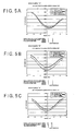
- Figs. 5A to 5C show curves, each (showing four curves) of which represents a relationship between radial tilt amounts and LPP amplitudes, obtained through measurement of three kinds of DVD-R disks "A” to “C.”
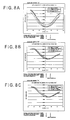
- Figs. 6A to 6C show curves, each (showing four curves) of which represents a relationship between radial tilt amounts and RF amplitudes, obtained through measurement of the foregoing same three kinds of DVD-R disks "A” to “C.” Any of the LPP and RF amplitudes were measured, with radial tilt amounts changed little by little, from the disks "A” to “C” with the use of the tilt correcting apparatus that employs a liquid crystal member serving as the tilt correcting mechanism.
- the amplitudes of the LPP signal are expressed as the negative-polarity signals, thus their absolute values showing amplitude amounts.
- the radial tilt amounts on each of the abscissa axes are scaled with tilt amounts to be set to the tilt correcting apparatus, thus being composed of voltage data to be given to the liquid-crystal type of tilt correcting apparatus employed by this example.
- each of Figs. 5A to 5C and 6A to 6C has four curves measured at four radial points on each disk (specifically, each point residing in each of inner, intermediate, outer, and outermost circumferential regions in the radial direction).
- any of the disks A to C provides a radial tilt amount maximizing the LPP signal amplitude, which is not zero and shifted toward either the positive- or negative-amount direction.
- the shifted directions and shifted amounts are different disk by disk. Even in the case of the same disk, different radial positions provide different radial tilt amounts respectively maximizing the LPP signal amplitudes which are slightly changed.
- any of the disks A to C provides a radial tilt amount maximizing the RF signal amplitude, which is not zero and shifted toward either the positive- or negative-amount direction.
- the shifted directions and shifted amounts are different disk by disk. Even in the case of the same disk, different radial positions provide different radial tilt amounts respectively maximizing the RF signal amplitudes which are slightly changed.
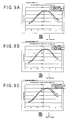
- radial tilt amounts each maximizing the RF signal amplitude are acquired individually from Figs. 6A to 6C, and then are handled as being zero (that is, located at the center of the abscissa axis) in order to rewrite the graphs shown in Figs. 5A to 5C into Figs. 7A to 7C.
- Figs. 7A to 7C reveal that, though being different disk by disk, the radial tilt amounts each maximizing the LPP signal amplitude are always offset by a constant amount from each of the radial tilt amounts maximizing RF signal amplitudes (that is, the positions of a radial tilt "zero" in each of Figs. 7A to 7C) independently of the radial positions on the same disk.
- any of the disks A to C provides a radial tilt amount maximizing the LPP signal amplitude, which is not zero and shifted toward either the positive- or negative-amount direction.
- the shifted directions and shifted amounts are different disk by disk. Even in the case of the same disk, different radial positions provide different radial tilt amounts each maximizing the LPP signal amplitudes which are slightly changed.
- any of the disks A to C provides a radial tilt amount maximizing the RF signal amplitude, which is not zero and shifted toward either the positive- or negative-amount direction.
- the shifted directions and shifted amounts are different disk by disk. Even in the case of the same disk, different radial positions provide different radial tilt amounts each maximizing the RF signal amplitudes which are slightly changed.
- radial tilt amounts each maximizing the RF signal amplitude are acquired individually from Figs. 9A to 9C, and then are handled as being zero to show Figs. 10A to 10C in which the radial tilt amounts are graphed in association with the LPP signal amplitudes shown in Figs. 8A to 8C.
- Figs. 10A to 10C reveal that, though being different disk by disk, the radial tilt amounts each maximizing the LPP signal amplitude are always offset by a constant amount from each of the radial tilt amounts maximizing RF signal amplitudes (that is, the positions of a radial tilt "zero" in each of Figs. 10A to 10C) independently of the radial positions on the same disk.
- a radial tilt amount that maximizes the LPP signal amplitude and an offset amount that has been pre-measured can be used to calculate a radial tilt amount that gives a maximum to the RF signal amplitude.
- the radial tilt is corrected through the performance of the microcomputer 12 that decides a tilt-correcting amount that maximizes the RF signal amplitude and controls the tilt-correcting driver 13 based on the tilt-correcting amount that has been decided.
- This control enables the correction under the tilt corrector 2a.
- the microcomputer 12 when the information recording/reproducing system 100 is loaded with a disk onto or from which bits of information are recorded or reproduced, the microcomputer 12 produces a correction profile to define tilt-correcting amounts for the disk to preserve the produced correction profile into the correcting profile memory 12a. In recording/reproducing bits of information, the correction profile is referred by the microcomputer 12 to execute the radial tilt correction.
- the correction profile is composed of data indicative of the relationship between the radial positions on the disk 1 and optimum tilt-correcting amounts at each of the radial positions.
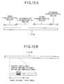
- radial positions on each disk can be defined as four positions belonging to each of radial inner, radial intermediate, radial outer, and radial outermost circumferential regions divided appropriately depending on radial distances from the center on the disk (refer to Fig. 15A) and an optimum tilt-correcting amount is assigned to each of the four positions.
- the optimum tilt-correcting amounts are decided so as to give a maximum to the amplitudes of an RF signal.
- a disk on which bits of information yet to be recorded is used, it is unable to detect an RF signal at each position on the disk, resulting in that tilt-correcting amounts maximizing the RF signal amplitude cannot be obtained.
- the characteristic that there is a constant offset ⁇ Tilt between a tilt amount maximizing the RF signal amplitude and another tilt amount maximizing the LPP signal amplitude on the same disk is utilized.
- a tilt amount maximizing the LPP signal amplitude is first acquired, and then a further tilt amount maximizing the RF signal amplitude is calculated based on both the acquired tilt amount and the offset ⁇ Tilt, so that an optimum tilt-correcting amount for the information-nonrecorded disk can be determined.
- This way of setting the optimum tilt-correcting amount makes it possible that even if a disk on which information has yet to be recorded is used, an optimum tilt amount can be decided with ease and a correction profile can be produced.
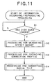
- each of the following sets of processing is mainly carried out by the microcomputer 12 in the information recording/reproducing system 100 (refer to Fig. 4), the microcomputer 12 being designed to execute previously prepared programs for the various sets of information recording/reproducing processing.
- this processing begins to start when a disk is loaded to the information recording/reproducing system 100.
- the microcomputer 12 determines if or not the information recording/reproducing system is loaded with a disk (step S1). The determination that the disk has been loaded is realized when the microcomputer 12 receives a signal from the detection mechanism for the disk.
- step S2 the microcomputer 12 proceeds to execution of the processing for offset-amount measurement
- the offset-amount measurement processing is directed to measurement of the foregoing offset ⁇ Tilt.
- RF-signal existence/nonexistence boundary between a region (information-recorded region) from which an RF signal can be detected and a further region (information-nonrecorded region) from which an RF signal cannot be detected.
- a read-in area on the disk includes a control data zone in which data is pre-recorded.
- Such a zone on a DVD-R disk is called “pre-write zone,” while such a zone on a DVD-RW disk is called “embossed zone.” Therefore, even if an information-nonrecorded disk is loaded, the boundary of the control data zone can be used as the RF-signal existence/nonexistence boundary" in measuring the offset.
- the microcomputer 12 first determines whether or not the disk that has been loaded is an information-nonrecorded disk (step S11). In the case that the loaded disk is a disk has already been subjected to recording of bits of information, management information about data to be recorded is recorded at an area immediately before the control data zone within the read-in area shown in Fig. 15B. In contrast, if the loaded disk has yet to be subjected to information recording, no such management information is recorded thereat. Hence, the microcomputer 12 is able to determine whether or not the loaded disk is an information-nonrecorded disk by confirming whether or not information is recorded in an area located immediately before the control data zone in the read-in area.
- the microcomputer 12 designates a pre-write zone (or embossed zone) shown in Fig. 15A as a point A (step S12). Then the microcomputer 12 designates a non-recorded section near the pre-write zone (or embossed zone) as a point B (step S13). The microcomputer 12 then changes a tilt-correcting amount to various amounts at the data-recorded point A to find out a tilt-correcting amount "Tilt A" that maximizes the RF signal amplitude (step S14).
- the microcomputer 12 changes a tilt-correcting amount to various amounts at the data-nonrecorded point B to find out a tilt-correcting amount "Tilt B" that maximizes the LPP signal amplitude (step S15).
- the microcomputer 12 uses the tilt-correcting amounts "Tilt A” and "Tilt B,” the microcomputer 12 calculates an offset ⁇ Tilt, before storing the calculated offset ⁇ Tilt into its inner memory or other memories (step S16).
- the microcomputer 12 searches for the RF-signal existence/nonexistence boundary from an innermost position toward the outer end on the disk (step S17). This search is carried out, with tracking servo opened, by moving the slider on with the pickup 2 toward the outer end on the disk and monitoring changes in the RF signal amplitude obtained during the moving operation of the pickup 2.
- the search shows the RF-signal existence/nonexistence boundary, the amplitude of the RF signal that has been obtained so far vanishes suddenly. It is therefore possible to recognize such a position as the RF-signal existence/nonexistence boundary.
- a recoded section near to the boundary is designated as the point "A" (step S19), before a non-recorded section near to the recoded section is designated as the point "B” (step S20).
- the microcomputer 12 then conducts the processing at steps S14 to S16 to calculate an offset ⁇ Tilt.
- step S18 In cases where it is determined at step S18 that the RF-signal existence/nonexistence boundary has not been detected, it can be recognized that the entire data recording region is filled with data and a correction profile can be produced based on the RF signal amplitude. In such a case, there is no need for measuring the offset ⁇ Tilt. The processing is therefore made to return to the main routine shown in Fig. 11.
- the above-mentioned offset measurement processing makes it possible that an offset ⁇ Tilt is obtained, regardless of the disk being an information-recorded disk or an information-nonrecorded disk.
- an information-recorded disk differs in the location of the RF-signal existence/nonexistence boundary from an information-nonrecorded disk, this difference will lead to no problem, because as explained before, the offset ⁇ Tilt is constant on the same disk independently of the radial positions thereon.
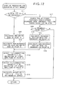
- Fig. 13 shows the processing for the production of a correction file.
- the microcomputer 12 makes the pickup 2 move to a predetermined reference position for the correction on the disk 1 (step S31).
- the reference position for the correction which is a position at which the radial tilt correction is performed, is a position belonging to, for example, each of the radial inner, radial intermediate, radial outer, and radial outermost circumferential regions divided appropriately depending on radial distances from the center on the disk 1 (refer to Fig. 15A). Therefore, for the first time, the reference position for the correction is set to a position residing in the inner circumferential region.
- the microcomputer then tries to read an RF signal at the first reference position for the correction to determine if or not the RF signal is obtained (step S32). If the RF signal cannot be obtained, it is understood that the reference position for the correction exists in an information-nonrecorded region on the disk.
- the microcomputer 12 uses the amplitude of an LPP signal to decide an optimum tilt-correcting amount. Specifically, as the radial tilt amount is altered little by little at the reference position for the correction to detect the LPP signal amplitudes, and a tilt-correcting amount showing a maximum of the detected LPP signal amplitudes is decided (step S33).
- the microcomputer 12 then adds the offset ⁇ Tilt obtained in the foregoing offset measurement processing, to the tilt-correcting amount obtained at step S33 (step S34).
- This addition produces a tilt amount identical to a tilt amount that maximizes the amplitude of an RF signal, thus serving as an optimum tilt-correcting amount.
- a tilt-correcting amount is altered every predetermined amount at the reference position for the correction, so that a particular tilt-correcting amount maximizing the RF signal amplitude can be decided, the particular tilt-correcting amount functioning as an optimum tilt-correcting amount (step S37).
- the microcomputer 12 stores the optimum tilt-correcting amount obtained at either step S34 or S37, into the correcting profile memory (step S35). Then, the microcomputer 12 moves to the determination whether or not the above processing has been competed at all the reference positions for the correction (step S36). If this determination shows the incompletion, the processing is made to shift to step S31 for the next reference position for the correction. This repetition allows all of the predetermined reference positions to be subjected to the decision of optimum tilt-correcting amounts, thus the correction profile being completed and its production processing being ended. The processing is then retuned to the main routine shown in Fig. 11.
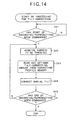
- the microcomputer 12 When the correction profile is completed, the microcomputer 12 is allowed to move to a recording or reproducing operation carried out under the correction of the radial tilt (step S4 in Fig. 11). This radial tilt correction carried out in parallel to the recording or reproducing operation is shown in Fig. 14. The microcomputer 12 achieves this radial tilt correction by controlling the tilt corrector 2a through the tilt-correcting driver 13.
- the microcomputer 12 When starting the processing shown in Fig. 14, the microcomputer 12 first determines if or not a user has commanded recording bits of information onto the disk 1 or reproduction of bits of information from the disk 1 (step S41). When it is determined that the recording or reproduction has been commanded, the microcomputer 12 utilizes an LPP signal or others to acquire an address to be targeted for the recording or reproduction (step S42), then acquires from the correcting profile memory 12a an optimum tilt-correcting amount corresponding to the acquired address (step S43). Further, the microcomputer 12 drives the tilt-correcting driver 13 on the basis of the acquired optimum tilt-correcting amount (step S44). The above processing at steps S42 to S44 is performed during the recording or reproducing operation.
- the microcomputer 12 determines whether or not the user has commanded the end of the recording or reproducing operation (step S45). Until the issuance of this end command, the processing lasts by repeating steps S42 to S44. When receiving the end command, the microcomputer 12 will terminate the processing.
- a first tilt amount maximizing the RF signal amplitude and a second tilt amount maximizing the LPP signal amplitude are obtained.
- the first and second tilt amounts are used to figure out an offset ⁇ Tilt.
- an optimum tilt amount is decided on the basis of either an RF signal if the disk has already been recorded with bits of information or a combination of an LPP signal and the offset ⁇ Tilt if the disk is yet to be recorded with bits of information, the decided optimum tilt amounts being memorized to form a correction profile.
- the correction profile is subjected to inquiries to conduct the radial tilt correction.
- the radial tilt correction becomes more accurate independently of types of disks.
- the information recording/reproducing system itself which is in charge of recording or reproducing bits of information, is able to decide optimum tilt-correcting amounts to produce a correction profile.
- the optimum tilt-correcting amounts can be decided with consideration of such characteristics, thus raising accuracy of the radial tilt correction.
- the correction profile is always produced prior to the recording and reproduction. This has less influence on the radial tilt correction, even if there are fluctuations in the recording or reproduction characteristics due to aging at the optical systems and/or due to changes in the temperature during the recording/reproduction operation.
- the present embodiment adopts the technique of producing a correction profile prior to actual recording or reproduction of information.
- a user who loads a disk into the information recording/reproducing system should wait for a long time until the recording or reproduction begins. It is therefore desired that the production of the correction profile be completed within as a shorter time as possible.
- a first technique is concerned with rotation control of a disk during the production of a correction profile.
- a light beam is moved to a predetermined reference position for the correction, where an LPP signal is detected as a tilt-correcting amount is changed little by little, thereby a tilt-correcting amount maximizing the LPP signal amplitude being decided. That is, the light beam is moved in turn to plural positions aligning in the radial direction on the disk, so that a tilt-correcting amount is decided at each redial position.
- the CLV control requires that a rotation velocity of the disk differs depending on each radial position on the disk. There is therefore the necessity of controlling the rotation velocity of the spindle motor into different velocities every time when the correcting reference positions are changed. In addition, it takes a certain period of time to make the rotation velocity of the spindle motor stabilized, thus leading to an excessively elongated time for producing a correction file.
- the information recording/reproducing system has the capability of simply rotating a disk on the CAV control; i.e., it is not always necessary to give the information recording/reproducing system itself the capability of acquiring address information and others according to the CAV control.
- a second technique concerns a reduction in the number of points to be measured.
- the number of measurement points can be lessened as follows.
- the relationship between the tilt-correcting amount and the LPP signal amplitude can be approximated to a quadratic function (parabolic curve).
- measuring the amplitudes of LPP signals at three points at a minimum i.e., different tilt-correcting amounts
- a function indicative of the tilt-correcting amounts and the LPP signal amplitudes is decided based on the measurement points using an approximation technique, and then a tilt-correcting amount showing a peak amount of the LPP signal amplitudes is assigned to a tilt-correcting amount to maximize the LPP signal amplitudes. This reduces the number of measurement points for measuring the LPP signal amplitudes, whereby the production of a correction profile can be speeded up.
- the foregoing embodiment has provided the configuration in which the LPPs (refer to Fig. 1) formed on the land existing on the radially outer side of a particular groove (in addition, adjacently thereto) undergo the detection of amplitude of an LPP signal.
- the LPPs formed on the land existing on the radially inner side of a particular groove may undergo the detection of amplitude of an LPP signal.
- the correlation between the detected LPP signal from the radially inner-side land and an RF signal from the groove may be used in the same way as the above.
- the amplitudes of LPP signals from both lands existing on both radially inner and outer sides of a particular groove may also be utilized together.
- the bottom hold circuit 11 has been used to detect the amplitude levels of the LPP signal.
- the quadrant photo detector PD shown in Fig. 1 is obliged to detect amplitude levels of a signal from the LPPs existing on the radially outer side of a recording track Gr.
- This bottom hold circuit 11 may be replaced by a peak hold circuit, so that amplitude levels of a signal from the LPPs existing on the radially inner side of a recording track Gr may be detected for use in deciding a tilt-correcting amount.
- Another alternative is that both the peak hold circuit and the bottom hold circuits are placed to detect amplitude levels of a signal from the LPPs existing on the radially inner and outer sides of a recording track Gr.
- both the offset measurement and the correction profile production are designed to be performed immediately after a disk is loaded into the information recording/reproducing system.
- various other timings other than the above, such as a period of time waiting for the next recording operation may be used for performing the offset measurement and the correction profile production.
Landscapes
- Optical Recording Or Reproduction (AREA)
Applications Claiming Priority (2)
| Application Number | Priority Date | Filing Date | Title |
|---|---|---|---|
| JP2002253589A JP3975139B2 (ja) | 2002-08-30 | 2002-08-30 | チルト補正装置及びチルト補正方法 |
| JP2002253589 | 2002-08-30 |
Publications (3)
| Publication Number | Publication Date |
|---|---|
| EP1394785A2 EP1394785A2 (en) | 2004-03-03 |
| EP1394785A3 EP1394785A3 (en) | 2005-04-20 |
| EP1394785B1 true EP1394785B1 (en) | 2007-07-25 |
Family
ID=31492647
Family Applications (1)
| Application Number | Title | Priority Date | Filing Date |
|---|---|---|---|
| EP03019516A Expired - Lifetime EP1394785B1 (en) | 2002-08-30 | 2003-08-28 | Method and apparatus for correcting tilt of light beam to optical recording medium |
Country Status (5)
| Country | Link |
|---|---|
| US (1) | US7187636B2 (https=) |
| EP (1) | EP1394785B1 (https=) |
| JP (1) | JP3975139B2 (https=) |
| CN (1) | CN1490797A (https=) |
| DE (1) | DE60315100D1 (https=) |
Families Citing this family (13)
| Publication number | Priority date | Publication date | Assignee | Title |
|---|---|---|---|---|
| AU2003242915A1 (en) * | 2002-07-26 | 2004-02-25 | Koninklijke Philips Electronics N.V. | Optical disc drive apparatus, method for measuring tilt of an optical disc, and method for correcting tilt of an optical disc |
| TWI270874B (en) * | 2003-08-11 | 2007-01-11 | Mediatek Inc | Method for calibrating tilt control value of a pickup |
| TWI228253B (en) * | 2003-08-13 | 2005-02-21 | Mediatek Inc | Method for real time calibrating tilt control value of a pickup |
| JP4537780B2 (ja) * | 2004-06-30 | 2010-09-08 | パイオニア株式会社 | チルト補正装置及び方法、情報記録装置、並びに情報記録再生装置 |
| KR100613611B1 (ko) * | 2004-07-07 | 2006-08-21 | 삼성전자주식회사 | 고주파 신호의 인벨롭을 이용하여 틸트/스큐를 보정하는 광디스크 재생장치 및 방법 |
| JP2006185563A (ja) * | 2004-12-28 | 2006-07-13 | Sony Corp | ディスク記録及び/又は再生装置及びそのチルト制御方法 |
| JP4556675B2 (ja) * | 2005-01-14 | 2010-10-06 | 船井電機株式会社 | チルト調整装置及びチルト調整方法 |
| JP2006236457A (ja) | 2005-02-24 | 2006-09-07 | Funai Electric Co Ltd | 光ディスク装置 |
| JP4816033B2 (ja) | 2005-12-01 | 2011-11-16 | 船井電機株式会社 | 光ディスク記録再生装置 |
| US7545725B2 (en) * | 2005-12-06 | 2009-06-09 | Daxon Technology Inc. | Optical reading apparatus capable of correcting aberration |
| WO2007123192A1 (ja) | 2006-04-21 | 2007-11-01 | Panasonic Corporation | 光ディスク装置 |
| JP2008034012A (ja) * | 2006-07-27 | 2008-02-14 | Sharp Corp | チルト量調整方法、光ピックアップ調整機構及び光ディスク装置 |
| JP2008041121A (ja) * | 2006-08-01 | 2008-02-21 | Sharp Corp | 光ディスク装置 |
Family Cites Families (11)
| Publication number | Priority date | Publication date | Assignee | Title |
|---|---|---|---|---|
| JP3545196B2 (ja) * | 1998-03-20 | 2004-07-21 | パイオニア株式会社 | チルトサーボ制御装置 |
| JP3690177B2 (ja) * | 1999-02-22 | 2005-08-31 | 三菱電機株式会社 | ディスク装置 |
| JP3776620B2 (ja) * | 1999-03-24 | 2006-05-17 | パイオニア株式会社 | 方向検出装置及び方向検出方法 |
| JP3736666B2 (ja) * | 1999-04-14 | 2006-01-18 | パイオニア株式会社 | チルトサーボ装置及び制御方法 |
| CN1201302C (zh) * | 1999-06-10 | 2005-05-11 | 索尼株式会社 | 具有倾斜检测装置的记录媒体驱动装置和倾斜检测方法 |
| JP3929207B2 (ja) * | 1999-07-08 | 2007-06-13 | パイオニア株式会社 | 光学式記録媒体のプリピット検出装置 |
| JP2002170266A (ja) * | 2000-12-01 | 2002-06-14 | Pioneer Electronic Corp | チルトサーボ制御装置及び方法 |
| JP2002170265A (ja) * | 2000-12-01 | 2002-06-14 | Pioneer Electronic Corp | チルトサーボ制御装置及び方法 |
| JP2002251739A (ja) * | 2001-02-21 | 2002-09-06 | Fujitsu Ltd | 位相補償方法及び光記憶装置 |
| JP2002288859A (ja) * | 2001-03-23 | 2002-10-04 | Toshiba Corp | ディスク装置とそのチルト検出方法 |
| JP2004022127A (ja) * | 2002-06-19 | 2004-01-22 | Pioneer Electronic Corp | チルト補正装置 |
-
2002
- 2002-08-30 JP JP2002253589A patent/JP3975139B2/ja not_active Expired - Fee Related
-
2003
- 2003-08-28 EP EP03019516A patent/EP1394785B1/en not_active Expired - Lifetime
- 2003-08-28 DE DE60315100T patent/DE60315100D1/de not_active Expired - Fee Related
- 2003-08-29 US US10/651,454 patent/US7187636B2/en not_active Expired - Fee Related
- 2003-08-29 CN CNA031556035A patent/CN1490797A/zh active Pending
Also Published As
| Publication number | Publication date |
|---|---|
| US20040042356A1 (en) | 2004-03-04 |
| US7187636B2 (en) | 2007-03-06 |
| DE60315100D1 (de) | 2007-09-06 |
| CN1490797A (zh) | 2004-04-21 |
| EP1394785A2 (en) | 2004-03-03 |
| EP1394785A3 (en) | 2005-04-20 |
| JP2004095035A (ja) | 2004-03-25 |
| JP3975139B2 (ja) | 2007-09-12 |
Similar Documents
| Publication | Publication Date | Title |
|---|---|---|
| US6842414B1 (en) | Apparatus and method for compensating tilt of optical disc | |
| EP1394785B1 (en) | Method and apparatus for correcting tilt of light beam to optical recording medium | |
| US20030099171A1 (en) | Optical disk apparatus and method for adjusting tilt therefor | |
| US7505383B2 (en) | Optical disc recording apparatus and method of forming an image on an optical disc | |
| US7170838B2 (en) | Information recording and reproducing apparatus | |
| US7436742B2 (en) | Optical recording device and aberration correction method | |
| US6970405B2 (en) | Optical recording/reproducing apparatus | |
| US7301869B2 (en) | Spherical aberration correcting method and apparatus | |
| US6625093B1 (en) | Apparatus and method for reproducing record for optical recording medium | |
| EP1385156B1 (en) | Spherical aberration correcting method and apparatus | |
| US20020048246A1 (en) | Optical recording medium, optical recording medium manufacturing apparatus, and optical recording medium manufacturing method | |
| US20040105361A1 (en) | Disk apparatus and disk recording method, and data reproduction method | |
| US6788627B2 (en) | Optical recording and reproducing apparatus, tilt correction method, tilt correction program and medium | |
| US7382698B2 (en) | Optical information recording/reproducing apparatus having tilt correction mechanism and method therefor | |
| US20040037195A1 (en) | Tilt correction device | |
| US20060291352A1 (en) | Optical disc recording control method and optical disc recording control apparatus | |
| US20080019236A1 (en) | Method for measuring a tilt control value of a pickup head in an optical disk drive | |
| KR100588442B1 (ko) | 광 디스크 장치의 기록 파워 결정 방법 및 기록 파워 제어방법 | |
| JP2005516335A (ja) | 記録キャリア、記録キャリアを走査するためのデバイスおよび方法 | |
| JP4218596B2 (ja) | 光ディスク装置 | |
| CN101084541B (zh) | 减小光记录载体读取器误差信号中径竖串扰的系统及方法 | |
| CN1841517A (zh) | 信息记录再现方法和信息记录再现装置 | |
| WO2005034100A2 (en) | Method of determining setting of spherical aberration corrector | |
| US20070014216A1 (en) | Method of determining recording power and optical disc drive apparatus | |
| JP3470105B2 (ja) | チルト検出装置および光ディスク装置、チルト検出方法 |
Legal Events
| Date | Code | Title | Description |
|---|---|---|---|
| PUAI | Public reference made under article 153(3) epc to a published international application that has entered the european phase |
Free format text: ORIGINAL CODE: 0009012 |
|
| AK | Designated contracting states |
Kind code of ref document: A2 Designated state(s): AT BE BG CH CY CZ DE DK EE ES FI FR GB GR HU IE IT LI LU MC NL PT RO SE SI SK TR |
|
| AX | Request for extension of the european patent |
Extension state: AL LT LV MK |
|
| PUAL | Search report despatched |
Free format text: ORIGINAL CODE: 0009013 |
|
| AK | Designated contracting states |
Kind code of ref document: A3 Designated state(s): AT BE BG CH CY CZ DE DK EE ES FI FR GB GR HU IE IT LI LU MC NL PT RO SE SI SK TR |
|
| AX | Request for extension of the european patent |
Extension state: AL LT LV MK |
|
| 17P | Request for examination filed |
Effective date: 20050530 |
|
| 17Q | First examination report despatched |
Effective date: 20050630 |
|
| AKX | Designation fees paid |
Designated state(s): DE FR GB |
|
| GRAP | Despatch of communication of intention to grant a patent |
Free format text: ORIGINAL CODE: EPIDOSNIGR1 |
|
| GRAS | Grant fee paid |
Free format text: ORIGINAL CODE: EPIDOSNIGR3 |
|
| GRAA | (expected) grant |
Free format text: ORIGINAL CODE: 0009210 |
|
| AK | Designated contracting states |
Kind code of ref document: B1 Designated state(s): DE FR GB |
|
| REG | Reference to a national code |
Ref country code: GB Ref legal event code: FG4D |
|
| REF | Corresponds to: |
Ref document number: 60315100 Country of ref document: DE Date of ref document: 20070906 Kind code of ref document: P |
|
| EN | Fr: translation not filed | ||
| PLBE | No opposition filed within time limit |
Free format text: ORIGINAL CODE: 0009261 |
|
| STAA | Information on the status of an ep patent application or granted ep patent |
Free format text: STATUS: NO OPPOSITION FILED WITHIN TIME LIMIT |
|
| GBPC | Gb: european patent ceased through non-payment of renewal fee |
Effective date: 20071025 |
|
| 26N | No opposition filed |
Effective date: 20080428 |
|
| PG25 | Lapsed in a contracting state [announced via postgrant information from national office to epo] |
Ref country code: DE Free format text: LAPSE BECAUSE OF NON-PAYMENT OF DUE FEES Effective date: 20080301 Ref country code: FR Free format text: LAPSE BECAUSE OF FAILURE TO SUBMIT A TRANSLATION OF THE DESCRIPTION OR TO PAY THE FEE WITHIN THE PRESCRIBED TIME-LIMIT Effective date: 20080321 |
|
| PG25 | Lapsed in a contracting state [announced via postgrant information from national office to epo] |
Ref country code: GB Free format text: LAPSE BECAUSE OF NON-PAYMENT OF DUE FEES Effective date: 20071025 |