EP1394478A1 - Dichtprofil für ein mit Schaum ausgespritztes Gehäuse - Google Patents
Dichtprofil für ein mit Schaum ausgespritztes Gehäuse Download PDFInfo
- Publication number
- EP1394478A1 EP1394478A1 EP03016769A EP03016769A EP1394478A1 EP 1394478 A1 EP1394478 A1 EP 1394478A1 EP 03016769 A EP03016769 A EP 03016769A EP 03016769 A EP03016769 A EP 03016769A EP 1394478 A1 EP1394478 A1 EP 1394478A1
- Authority
- EP
- European Patent Office
- Prior art keywords
- housing
- foam
- housing parts
- sealing profile
- housing part
- Prior art date
- Legal status (The legal status is an assumption and is not a legal conclusion. Google has not performed a legal analysis and makes no representation as to the accuracy of the status listed.)
- Granted
Links
- 239000006260 foam Substances 0.000 title claims abstract description 34
- 238000007789 sealing Methods 0.000 title claims description 15
- XLYOFNOQVPJJNP-UHFFFAOYSA-N water Substances O XLYOFNOQVPJJNP-UHFFFAOYSA-N 0.000 claims abstract description 5
- 230000005489 elastic deformation Effects 0.000 claims abstract description 4
- 239000011324 bead Substances 0.000 description 4
- 239000000203 mixture Substances 0.000 description 4
- 210000004027 cell Anatomy 0.000 description 2
- 238000005187 foaming Methods 0.000 description 2
- 238000004519 manufacturing process Methods 0.000 description 2
- 239000000463 material Substances 0.000 description 2
- 239000003380 propellant Substances 0.000 description 2
- 239000002390 adhesive tape Substances 0.000 description 1
- 210000003850 cellular structure Anatomy 0.000 description 1
- 238000010276 construction Methods 0.000 description 1
- 230000007423 decrease Effects 0.000 description 1
- 238000000034 method Methods 0.000 description 1
- 229920005903 polyol mixture Polymers 0.000 description 1
- 238000004886 process control Methods 0.000 description 1
- 238000004064 recycling Methods 0.000 description 1
- 238000005507 spraying Methods 0.000 description 1
- 230000000087 stabilizing effect Effects 0.000 description 1
Images





Classifications
-
- F—MECHANICAL ENGINEERING; LIGHTING; HEATING; WEAPONS; BLASTING
- F24—HEATING; RANGES; VENTILATING
- F24H—FLUID HEATERS, e.g. WATER OR AIR HEATERS, HAVING HEAT-GENERATING MEANS, e.g. HEAT PUMPS, IN GENERAL
- F24H9/00—Details
- F24H9/02—Casings; Cover lids; Ornamental panels
-
- F—MECHANICAL ENGINEERING; LIGHTING; HEATING; WEAPONS; BLASTING
- F24—HEATING; RANGES; VENTILATING
- F24H—FLUID HEATERS, e.g. WATER OR AIR HEATERS, HAVING HEAT-GENERATING MEANS, e.g. HEAT PUMPS, IN GENERAL
- F24H1/00—Water heaters, e.g. boilers, continuous-flow heaters or water-storage heaters
- F24H1/18—Water-storage heaters
- F24H1/181—Construction of the tank
- F24H1/182—Insulation
Definitions
- the invention relates to a sealing profile for a sprayed with foam housing.
- the aim of the invention is to avoid these disadvantages and an insulated housing create, which can be filled with a simple effort with foam, in which no foam escapes through joints and at the same time has a stiff construction.
- a fixed connection between the Housing parts can be achieved without separate connection means.
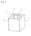
- Fig. 1 shows a hot water tank 5 in a housing 4, over at least two Housing parts 1, 2 has. While in Fig. 1, the housing 4 is open and without foam is in Fig. 2, the same housing 4 closed with foam 3 to see. Between the Hot water tank 5 and the housing parts 1, 2 is a heat-insulating Foam 3, which in addition to the heat-insulating function and the housing 4 and the parts in it are stability.
- the two housing parts 1, 2 according to the figures Fig. 3 to grab Fig. 7 in sections 11, 21 engaging behind one another.
- the two housing parts 1, 2 be joined together so that the gap between the housing part 1 of the Housing part 2 is closed.
- Fig. 3 shows a variant of the sealing profile according to the invention.
- the housing part 1 has a bead 7 just before a final edge 9.
- the housing part 2 has also over a bead 7 just before a final fold 8.
- the two housing parts 1, 2 are joined together in such a way that the end edge 9 of the housing part 1 is linear to the bead 7 of the housing part 2 abuts.
- the final edge folds behind 8 of the housing part 2 line in the bead 7 of the housing part 1.
- Rivets 6 hold the Housing parts 1, 2 together.
- the Abschlußumkantung 8 and the end edge 9th deform elastically and provide a compressive stress in the contact area.
- Within the housing 4 is Dämmschaum 3.
- Fig. 4 shows a sealing profile, which does not require separate connection means.
- the Housing parts 1, 2 are matched to one another such that they elastically spring into one another intervention.
- the two partial surfaces 11, 21 are designed as springs, which over each other vertical support surfaces 10, 12, on which the housing parts 1, 2 abut each other, feature.
- the housing part 1 has an angled portion 13 and the Housing part 2 via a bend 14.
- the bend 14 engages in the bend 13, wherein the angle between the support surface 12 and the bend 14 is smaller than that Angle between the support surface 12 and the bend 13. This creates positive engagement through the support surfaces 10 and 12 and the line contact between the bends 13th and 14.
- the elastic deformation of the housing parts 1, 2 also creates adhesion.
- a snap-in aid 15 facilitates the elastic deformation of the housing part 1, so that the housing part 2 can be inserted.
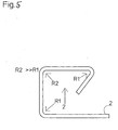
- Fig. 5 shows the housing part 2 in detail.
- Fig. 6 shows a similar sealing profile, but in comparison to FIG. 4 via no Angles 13, 14 features. Instead, the end edge 8 of the Housing part 1 line on the housing part. 2
- a housing 4 can be seen, in which a housing part 1 substantially is designed around and in the portion 11, 21 at the end bends 13, 14 into each other intervention.
- the tension in the housing part 1 ensures the adhesion along the linear form fit line.
- the manufacturing process provides that predominantly foams based on a polyol mixture (Hard foam system) can be used.
- the housing parts 1, 2 are assembled so that they have tight joints (as described above). With a lot short so-called shot times (about 2-3 sec.)
- the foam mixture in the form space between the housing 4 and hot water tank 5) by spraying from a nozzle introduced: The mixture starts immediately after leaving the nozzle to drive up the room completely filled.
- the housing is held pressure-proof in the foam mold, so that even with resulting overpressures the desired excess quantities Hard foam mixture can be safely spent. By the amount and the pressure leaves affect the density of the foam.
- Open cell foam is particularly suitable for recycling, has a low density on, however, has no high stability, so that open-cell foam only limited carrying material can be used.
- the entire foaming process must - in order to be able to be controlled reproducibly - in all parameters (times, processing temperature, etc.) is and is monitored Very sensitive to deviations.
- the process control should accordingly Run as automated as possible, since in case of deviations the entire foamed Product is scrap and the foamed object only after manual "peeling" can be returned to production.
Landscapes
- Engineering & Computer Science (AREA)
- Physics & Mathematics (AREA)
- Thermal Sciences (AREA)
- Chemical & Material Sciences (AREA)
- Combustion & Propulsion (AREA)
- Mechanical Engineering (AREA)
- General Engineering & Computer Science (AREA)
- Casting Or Compression Moulding Of Plastics Or The Like (AREA)
- Moulds For Moulding Plastics Or The Like (AREA)
- Gasket Seals (AREA)
- Coating By Spraying Or Casting (AREA)
Abstract
Description
Claims (6)
- Dichtprofil für ein mit Schaum (3) ausgespritztes Gehäuse (4) mit einem oder mehreren Gehäuseteilen (1, 2), welche aneinander anliegen, dadurch gekennzeichnet, dass Teilflächen (11, 21) der Gehäuseteile (1, 2) einander hintergreifen.
- Dichtprofil gemäß Anspruch 1, dadurch gekennzeichnet, dass die Gehäuseteile (1, 2) unter Spannung miteinander verbunden sind.
- Dichtprofil gemäß einem der Ansprüche 1 oder 2, dadurch gekennzeichnet, dass die Gehäuseteile (1, 2) durch Verbindungsmittel (6) verbunden sind.
- Dichtprofil gemäß einem der Ansprüche 1 bis 3, dadurch gekennzeichnet, dass die Gehäuseteile (1, 2) durch elastische Verformung verbunden sind.
- Dichtprofil gemäß einem der Ansprüche 1 bis 4, dadurch gekennzeichnet, dass die Gehäuseteile (1, 2) durch zwei Linienberührungen miteinander Kontakt haben.
- Dichtprofil gemäß einem der Ansprüche 1 bis 5, dadurch gekennzeichnet, dass in dem Gehäuse (4) ein Warmwasserspeicher (5) angeordnet ist.
Priority Applications (1)
| Application Number | Priority Date | Filing Date | Title |
|---|---|---|---|
| AT03016769T ATE403119T1 (de) | 2002-08-30 | 2003-07-23 | Dichtprofil für ein mit schaum ausgespritztes gehäuse |
Applications Claiming Priority (2)
| Application Number | Priority Date | Filing Date | Title |
|---|---|---|---|
| AT12962002 | 2002-08-30 | ||
| AT0129602A AT411932B (de) | 2002-08-30 | 2002-08-30 | Dichtprofil für ein mit schaum ausgespritztes gehäuse |
Publications (2)
| Publication Number | Publication Date |
|---|---|
| EP1394478A1 true EP1394478A1 (de) | 2004-03-03 |
| EP1394478B1 EP1394478B1 (de) | 2008-07-30 |
Family
ID=29588449
Family Applications (1)
| Application Number | Title | Priority Date | Filing Date |
|---|---|---|---|
| EP03016769A Expired - Lifetime EP1394478B1 (de) | 2002-08-30 | 2003-07-23 | Dichtprofil für ein mit Schaum ausgespritztes Gehäuse |
Country Status (3)
| Country | Link |
|---|---|
| EP (1) | EP1394478B1 (de) |
| AT (2) | AT411932B (de) |
| DE (2) | DE50310229D1 (de) |
Cited By (2)
| Publication number | Priority date | Publication date | Assignee | Title |
|---|---|---|---|---|
| EP2918944A1 (de) * | 2014-02-21 | 2015-09-16 | Vaillant GmbH | Gehäuse |
| CN116044999A (zh) * | 2022-12-26 | 2023-05-02 | 中国石油天然气股份有限公司 | 一种弹簧蓄能密封组件、装置及使用方法和应用 |
Families Citing this family (1)
| Publication number | Priority date | Publication date | Assignee | Title |
|---|---|---|---|---|
| CN111981690B (zh) * | 2019-05-23 | 2022-05-10 | 青岛经济技术开发区海尔热水器有限公司 | 热水器外壳及热水器 |
Citations (2)
| Publication number | Priority date | Publication date | Assignee | Title |
|---|---|---|---|---|
| US5020481A (en) * | 1989-02-13 | 1991-06-04 | Nelson Thomas E | Thermal insulation jacket |
| EP0797055A1 (de) * | 1996-03-18 | 1997-09-24 | Atlantic - Société Française de Développement Thermique | Verfahren zum Herstellen eines Wasserheizers und entsprechender Wasserheizer |
Family Cites Families (1)
| Publication number | Priority date | Publication date | Assignee | Title |
|---|---|---|---|---|
| AT408808B (de) * | 1998-03-23 | 2002-03-25 | Vaillant Gmbh | Verkleidung für einen kessel |
-
2002
- 2002-08-30 AT AT0129602A patent/AT411932B/de not_active IP Right Cessation
-
2003
- 2003-07-23 AT AT03016769T patent/ATE403119T1/de active
- 2003-07-23 DE DE50310229T patent/DE50310229D1/de not_active Expired - Lifetime
- 2003-07-23 EP EP03016769A patent/EP1394478B1/de not_active Expired - Lifetime
- 2003-07-23 DE DE10333364A patent/DE10333364A1/de not_active Withdrawn
Patent Citations (2)
| Publication number | Priority date | Publication date | Assignee | Title |
|---|---|---|---|---|
| US5020481A (en) * | 1989-02-13 | 1991-06-04 | Nelson Thomas E | Thermal insulation jacket |
| EP0797055A1 (de) * | 1996-03-18 | 1997-09-24 | Atlantic - Société Française de Développement Thermique | Verfahren zum Herstellen eines Wasserheizers und entsprechender Wasserheizer |
Cited By (2)
| Publication number | Priority date | Publication date | Assignee | Title |
|---|---|---|---|---|
| EP2918944A1 (de) * | 2014-02-21 | 2015-09-16 | Vaillant GmbH | Gehäuse |
| CN116044999A (zh) * | 2022-12-26 | 2023-05-02 | 中国石油天然气股份有限公司 | 一种弹簧蓄能密封组件、装置及使用方法和应用 |
Also Published As
| Publication number | Publication date |
|---|---|
| DE50310229D1 (de) | 2008-09-11 |
| EP1394478B1 (de) | 2008-07-30 |
| DE10333364A1 (de) | 2004-03-11 |
| AT411932B (de) | 2004-07-26 |
| ATE403119T1 (de) | 2008-08-15 |
| ATA12962002A (de) | 2003-12-15 |
Similar Documents
| Publication | Publication Date | Title |
|---|---|---|
| EP2171168B1 (de) | Profilelement mit Dichtungselement und Herstellungsverfahren dafür | |
| EP3256662B2 (de) | Fugendichtband mit vorbestimmter geometrie und dichtanordnung mit derartigem fugendichtband | |
| DE4028895C1 (en) | Foamed component made of elastic, flexible plastic - used for sound insulation, consists of hollow chassis into which polyurethane foam unit is adhered inside and unit is seated | |
| DE2841934A1 (de) | Waermeisoliertes leitungsrohr und verfahren zu seiner herstellung | |
| EP3568539A1 (de) | Brandschutzprofil, brandschutzfugenbaugruppe und verfahren zur montage einer brandschutzfugenbaugruppe | |
| DE3234808A1 (de) | Dichtungsstreifen fuer fugen sowie mit diesem abgedichtete fugen | |
| DE2117523A1 (en) | Moulded furniture - with semi-finished sheet inserted in mould to be incorporated in foam plastic | |
| EP1394478B1 (de) | Dichtprofil für ein mit Schaum ausgespritztes Gehäuse | |
| DE3723394A1 (de) | Daemmkassette und verfahren zu ihrer herstellung | |
| EP2861305B1 (de) | Innenverkleidung für transportmittel mit einem brandschutzlack | |
| DE10318868A1 (de) | Dämmelement, Vorrichtung zur Herstellung des Dämmelements und Herstellungsverfahren | |
| DE102015011689A1 (de) | Gekantetes oder zur Kantung vorgesehenes Blech | |
| DE102015111714A1 (de) | Zarge für Brandschutztüren | |
| DE3801568A1 (de) | Tor- oder tuerblattfluegel | |
| DE2446858A1 (de) | Wohnraumtuer und verfahren sowie vorrichtung zu ihrer herstellung | |
| DE3609332C2 (de) | ||
| DE102011108590A1 (de) | Verbindungssteg für ein Verbundprofil | |
| DE3049569A1 (de) | "verfahren zur herstellung von profilen, sowie dazugehoerige profilteilkoerper" | |
| DE102015112154A1 (de) | Verfahren zur Herstellung eines Dämmelements sowie ein entsprechendes Dämmelement | |
| DE2606887A1 (de) | Eckverbindung zwischen zwei wandteilen eines moebelstueckes, gehaeuses o.dgl. | |
| EP4248157A1 (de) | Kältegerät mit einem ventilelement zum verschliessen einer einfüllöffnung für isolationsmaterial | |
| DE10039158A1 (de) | Dämmelement und Verfahren zu seiner Herstellung | |
| DE102020117198A1 (de) | Verfahren zur Herstellung eines Verbundprofils und Verbundprofil | |
| DE1484101C (de) | Verfahren zur Herstellung einer zusammengesetzten Tafel aus einem geschäumten Isolierelement | |
| DE2845335C2 (de) | Verfahren zur Vermeidung von Verhärtungen an Weichschaum-Formkörpern |
Legal Events
| Date | Code | Title | Description |
|---|---|---|---|
| PUAI | Public reference made under article 153(3) epc to a published international application that has entered the european phase |
Free format text: ORIGINAL CODE: 0009012 |
|
| AK | Designated contracting states |
Kind code of ref document: A1 Designated state(s): AT BE BG CH CY CZ DE DK EE ES FI FR GB GR HU IE IT LI LU MC NL PT RO SE SI SK TR |
|
| AX | Request for extension of the european patent |
Extension state: AL LT LV MK |
|
| 17P | Request for examination filed |
Effective date: 20040526 |
|
| AKX | Designation fees paid |
Designated state(s): AT BE BG CH CY CZ DE DK EE ES FI FR GB GR HU IE IT LI LU MC NL PT RO SE SI SK TR |
|
| 17Q | First examination report despatched |
Effective date: 20050324 |
|
| GRAP | Despatch of communication of intention to grant a patent |
Free format text: ORIGINAL CODE: EPIDOSNIGR1 |
|
| GRAS | Grant fee paid |
Free format text: ORIGINAL CODE: EPIDOSNIGR3 |
|
| GRAA | (expected) grant |
Free format text: ORIGINAL CODE: 0009210 |
|
| AK | Designated contracting states |
Kind code of ref document: B1 Designated state(s): AT BE BG CH CY CZ DE DK EE ES FI FR GB GR HU IE IT LI LU MC NL PT RO SE SI SK TR |
|
| REG | Reference to a national code |
Ref country code: GB Ref legal event code: FG4D Free format text: NOT ENGLISH |
|
| REG | Reference to a national code |
Ref country code: CH Ref legal event code: EP |
|
| REF | Corresponds to: |
Ref document number: 50310229 Country of ref document: DE Date of ref document: 20080911 Kind code of ref document: P |
|
| REG | Reference to a national code |
Ref country code: IE Ref legal event code: FG4D Free format text: LANGUAGE OF EP DOCUMENT: GERMAN |
|
| PG25 | Lapsed in a contracting state [announced via postgrant information from national office to epo] |
Ref country code: PT Free format text: LAPSE BECAUSE OF FAILURE TO SUBMIT A TRANSLATION OF THE DESCRIPTION OR TO PAY THE FEE WITHIN THE PRESCRIBED TIME-LIMIT Effective date: 20081230 Ref country code: ES Free format text: LAPSE BECAUSE OF FAILURE TO SUBMIT A TRANSLATION OF THE DESCRIPTION OR TO PAY THE FEE WITHIN THE PRESCRIBED TIME-LIMIT Effective date: 20081110 Ref country code: NL Free format text: LAPSE BECAUSE OF FAILURE TO SUBMIT A TRANSLATION OF THE DESCRIPTION OR TO PAY THE FEE WITHIN THE PRESCRIBED TIME-LIMIT Effective date: 20080730 |
|
| PG25 | Lapsed in a contracting state [announced via postgrant information from national office to epo] |
Ref country code: BG Free format text: LAPSE BECAUSE OF FAILURE TO SUBMIT A TRANSLATION OF THE DESCRIPTION OR TO PAY THE FEE WITHIN THE PRESCRIBED TIME-LIMIT Effective date: 20081030 Ref country code: FI Free format text: LAPSE BECAUSE OF FAILURE TO SUBMIT A TRANSLATION OF THE DESCRIPTION OR TO PAY THE FEE WITHIN THE PRESCRIBED TIME-LIMIT Effective date: 20080730 Ref country code: SI Free format text: LAPSE BECAUSE OF FAILURE TO SUBMIT A TRANSLATION OF THE DESCRIPTION OR TO PAY THE FEE WITHIN THE PRESCRIBED TIME-LIMIT Effective date: 20080730 |
|
| REG | Reference to a national code |
Ref country code: IE Ref legal event code: FD4D |
|
| PG25 | Lapsed in a contracting state [announced via postgrant information from national office to epo] |
Ref country code: DK Free format text: LAPSE BECAUSE OF FAILURE TO SUBMIT A TRANSLATION OF THE DESCRIPTION OR TO PAY THE FEE WITHIN THE PRESCRIBED TIME-LIMIT Effective date: 20080730 Ref country code: EE Free format text: LAPSE BECAUSE OF FAILURE TO SUBMIT A TRANSLATION OF THE DESCRIPTION OR TO PAY THE FEE WITHIN THE PRESCRIBED TIME-LIMIT Effective date: 20080730 Ref country code: IE Free format text: LAPSE BECAUSE OF FAILURE TO SUBMIT A TRANSLATION OF THE DESCRIPTION OR TO PAY THE FEE WITHIN THE PRESCRIBED TIME-LIMIT Effective date: 20080730 |
|
| PG25 | Lapsed in a contracting state [announced via postgrant information from national office to epo] |
Ref country code: CZ Free format text: LAPSE BECAUSE OF FAILURE TO SUBMIT A TRANSLATION OF THE DESCRIPTION OR TO PAY THE FEE WITHIN THE PRESCRIBED TIME-LIMIT Effective date: 20080730 Ref country code: RO Free format text: LAPSE BECAUSE OF FAILURE TO SUBMIT A TRANSLATION OF THE DESCRIPTION OR TO PAY THE FEE WITHIN THE PRESCRIBED TIME-LIMIT Effective date: 20080730 Ref country code: SK Free format text: LAPSE BECAUSE OF FAILURE TO SUBMIT A TRANSLATION OF THE DESCRIPTION OR TO PAY THE FEE WITHIN THE PRESCRIBED TIME-LIMIT Effective date: 20080730 |
|
| PLBE | No opposition filed within time limit |
Free format text: ORIGINAL CODE: 0009261 |
|
| STAA | Information on the status of an ep patent application or granted ep patent |
Free format text: STATUS: NO OPPOSITION FILED WITHIN TIME LIMIT |
|
| 26N | No opposition filed |
Effective date: 20090506 |
|
| PG25 | Lapsed in a contracting state [announced via postgrant information from national office to epo] |
Ref country code: IT Free format text: LAPSE BECAUSE OF FAILURE TO SUBMIT A TRANSLATION OF THE DESCRIPTION OR TO PAY THE FEE WITHIN THE PRESCRIBED TIME-LIMIT Effective date: 20080730 |
|
| PG25 | Lapsed in a contracting state [announced via postgrant information from national office to epo] |
Ref country code: SE Free format text: LAPSE BECAUSE OF FAILURE TO SUBMIT A TRANSLATION OF THE DESCRIPTION OR TO PAY THE FEE WITHIN THE PRESCRIBED TIME-LIMIT Effective date: 20081030 |
|
| BERE | Be: lapsed |
Owner name: VAILLANT G.M.B.H. Effective date: 20090731 |
|
| PG25 | Lapsed in a contracting state [announced via postgrant information from national office to epo] |
Ref country code: MC Free format text: LAPSE BECAUSE OF NON-PAYMENT OF DUE FEES Effective date: 20090731 |
|
| PG25 | Lapsed in a contracting state [announced via postgrant information from national office to epo] |
Ref country code: BE Free format text: LAPSE BECAUSE OF NON-PAYMENT OF DUE FEES Effective date: 20090731 |
|
| PG25 | Lapsed in a contracting state [announced via postgrant information from national office to epo] |
Ref country code: GR Free format text: LAPSE BECAUSE OF FAILURE TO SUBMIT A TRANSLATION OF THE DESCRIPTION OR TO PAY THE FEE WITHIN THE PRESCRIBED TIME-LIMIT Effective date: 20081031 |
|
| PG25 | Lapsed in a contracting state [announced via postgrant information from national office to epo] |
Ref country code: LU Free format text: LAPSE BECAUSE OF NON-PAYMENT OF DUE FEES Effective date: 20090723 |
|
| PG25 | Lapsed in a contracting state [announced via postgrant information from national office to epo] |
Ref country code: HU Free format text: LAPSE BECAUSE OF FAILURE TO SUBMIT A TRANSLATION OF THE DESCRIPTION OR TO PAY THE FEE WITHIN THE PRESCRIBED TIME-LIMIT Effective date: 20090131 |
|
| PG25 | Lapsed in a contracting state [announced via postgrant information from national office to epo] |
Ref country code: TR Free format text: LAPSE BECAUSE OF FAILURE TO SUBMIT A TRANSLATION OF THE DESCRIPTION OR TO PAY THE FEE WITHIN THE PRESCRIBED TIME-LIMIT Effective date: 20080730 |
|
| PG25 | Lapsed in a contracting state [announced via postgrant information from national office to epo] |
Ref country code: CY Free format text: LAPSE BECAUSE OF FAILURE TO SUBMIT A TRANSLATION OF THE DESCRIPTION OR TO PAY THE FEE WITHIN THE PRESCRIBED TIME-LIMIT Effective date: 20080730 |
|
| REG | Reference to a national code |
Ref country code: FR Ref legal event code: PLFP Year of fee payment: 13 |
|
| PGFP | Annual fee paid to national office [announced via postgrant information from national office to epo] |
Ref country code: GB Payment date: 20150629 Year of fee payment: 13 |
|
| PGFP | Annual fee paid to national office [announced via postgrant information from national office to epo] |
Ref country code: CH Payment date: 20150708 Year of fee payment: 13 |
|
| PGFP | Annual fee paid to national office [announced via postgrant information from national office to epo] |
Ref country code: AT Payment date: 20150706 Year of fee payment: 13 Ref country code: FR Payment date: 20150706 Year of fee payment: 13 |
|
| REG | Reference to a national code |
Ref country code: CH Ref legal event code: PL |
|
| REG | Reference to a national code |
Ref country code: AT Ref legal event code: MM01 Ref document number: 403119 Country of ref document: AT Kind code of ref document: T Effective date: 20160723 |
|
| GBPC | Gb: european patent ceased through non-payment of renewal fee |
Effective date: 20160723 |
|
| PG25 | Lapsed in a contracting state [announced via postgrant information from national office to epo] |
Ref country code: CH Free format text: LAPSE BECAUSE OF NON-PAYMENT OF DUE FEES Effective date: 20160731 Ref country code: FR Free format text: LAPSE BECAUSE OF NON-PAYMENT OF DUE FEES Effective date: 20160801 Ref country code: LI Free format text: LAPSE BECAUSE OF NON-PAYMENT OF DUE FEES Effective date: 20160731 |
|
| REG | Reference to a national code |
Ref country code: FR Ref legal event code: ST Effective date: 20170331 |
|
| PG25 | Lapsed in a contracting state [announced via postgrant information from national office to epo] |
Ref country code: GB Free format text: LAPSE BECAUSE OF NON-PAYMENT OF DUE FEES Effective date: 20160723 Ref country code: AT Free format text: LAPSE BECAUSE OF NON-PAYMENT OF DUE FEES Effective date: 20160723 |
|
| PGFP | Annual fee paid to national office [announced via postgrant information from national office to epo] |
Ref country code: DE Payment date: 20220628 Year of fee payment: 20 |
|
| REG | Reference to a national code |
Ref country code: DE Ref legal event code: R071 Ref document number: 50310229 Country of ref document: DE |