EP1391561A2 - Bohrvorrichtung - Google Patents
Bohrvorrichtung Download PDFInfo
- Publication number
- EP1391561A2 EP1391561A2 EP03016166A EP03016166A EP1391561A2 EP 1391561 A2 EP1391561 A2 EP 1391561A2 EP 03016166 A EP03016166 A EP 03016166A EP 03016166 A EP03016166 A EP 03016166A EP 1391561 A2 EP1391561 A2 EP 1391561A2
- Authority
- EP
- European Patent Office
- Prior art keywords
- concrete
- pump
- concrete pump
- drilling device
- drilling
- Prior art date
- Legal status (The legal status is an assumption and is not a legal conclusion. Google has not performed a legal analysis and makes no representation as to the accuracy of the status listed.)
- Granted
Links
- 238000005553 drilling Methods 0.000 title claims description 35
- XLYOFNOQVPJJNP-UHFFFAOYSA-N water Substances O XLYOFNOQVPJJNP-UHFFFAOYSA-N 0.000 claims description 7
- 238000006073 displacement reaction Methods 0.000 claims description 4
- 238000012546 transfer Methods 0.000 claims description 4
- 238000005253 cladding Methods 0.000 claims 1
- 238000003780 insertion Methods 0.000 claims 1
- 230000037431 insertion Effects 0.000 claims 1
- 238000000034 method Methods 0.000 description 12
- 238000010276 construction Methods 0.000 description 5
- 238000004519 manufacturing process Methods 0.000 description 5
- 238000005086 pumping Methods 0.000 description 3
- 239000002689 soil Substances 0.000 description 3
- 230000009897 systematic effect Effects 0.000 description 3
- 241000237858 Gastropoda Species 0.000 description 2
- 238000002156 mixing Methods 0.000 description 2
- 244000089486 Phragmites australis subsp australis Species 0.000 description 1
- 229910000831 Steel Inorganic materials 0.000 description 1
- 238000013459 approach Methods 0.000 description 1
- 238000001816 cooling Methods 0.000 description 1
- 230000001419 dependent effect Effects 0.000 description 1
- 238000005429 filling process Methods 0.000 description 1
- 239000003673 groundwater Substances 0.000 description 1
- 239000000463 material Substances 0.000 description 1
- 238000013021 overheating Methods 0.000 description 1
- 230000002572 peristaltic effect Effects 0.000 description 1
- 230000008092 positive effect Effects 0.000 description 1
- 230000002028 premature Effects 0.000 description 1
- 238000012545 processing Methods 0.000 description 1
- 230000002250 progressing effect Effects 0.000 description 1
- 230000005855 radiation Effects 0.000 description 1
- 238000005096 rolling process Methods 0.000 description 1
- 238000007789 sealing Methods 0.000 description 1
- 230000000087 stabilizing effect Effects 0.000 description 1
- 239000010959 steel Substances 0.000 description 1
- 239000000126 substance Substances 0.000 description 1
- 230000037072 sun protection Effects 0.000 description 1
- 238000010792 warming Methods 0.000 description 1
Images

Classifications
-
- E—FIXED CONSTRUCTIONS
- E02—HYDRAULIC ENGINEERING; FOUNDATIONS; SOIL SHIFTING
- E02D—FOUNDATIONS; EXCAVATIONS; EMBANKMENTS; UNDERGROUND OR UNDERWATER STRUCTURES
- E02D5/00—Bulkheads, piles, or other structural elements specially adapted to foundation engineering
- E02D5/22—Piles
- E02D5/34—Concrete or concrete-like piles cast in position ; Apparatus for making same
- E02D5/38—Concrete or concrete-like piles cast in position ; Apparatus for making same making by use of mould-pipes or other moulds
- E02D5/385—Concrete or concrete-like piles cast in position ; Apparatus for making same making by use of mould-pipes or other moulds with removal of the outer mould-pipes
-
- E—FIXED CONSTRUCTIONS
- E02—HYDRAULIC ENGINEERING; FOUNDATIONS; SOIL SHIFTING
- E02D—FOUNDATIONS; EXCAVATIONS; EMBANKMENTS; UNDERGROUND OR UNDERWATER STRUCTURES
- E02D15/00—Handling building or like materials for hydraulic engineering or foundations
- E02D15/02—Handling of bulk concrete specially for foundation or hydraulic engineering purposes
- E02D15/04—Placing concrete in mould-pipes, pile tubes, bore-holes or narrow shafts
-
- E—FIXED CONSTRUCTIONS
- E02—HYDRAULIC ENGINEERING; FOUNDATIONS; SOIL SHIFTING
- E02D—FOUNDATIONS; EXCAVATIONS; EMBANKMENTS; UNDERGROUND OR UNDERWATER STRUCTURES
- E02D5/00—Bulkheads, piles, or other structural elements specially adapted to foundation engineering
- E02D5/22—Piles
- E02D5/34—Concrete or concrete-like piles cast in position ; Apparatus for making same
- E02D5/36—Concrete or concrete-like piles cast in position ; Apparatus for making same making without use of mouldpipes or other moulds
-
- E—FIXED CONSTRUCTIONS
- E02—HYDRAULIC ENGINEERING; FOUNDATIONS; SOIL SHIFTING
- E02D—FOUNDATIONS; EXCAVATIONS; EMBANKMENTS; UNDERGROUND OR UNDERWATER STRUCTURES
- E02D5/00—Bulkheads, piles, or other structural elements specially adapted to foundation engineering
- E02D5/22—Piles
- E02D5/34—Concrete or concrete-like piles cast in position ; Apparatus for making same
- E02D5/38—Concrete or concrete-like piles cast in position ; Apparatus for making same making by use of mould-pipes or other moulds
Definitions
- Figure 1 shows an embodiment in which a drill is shown with the bored piles using the drilling method continuous auger. After screwing in the screw to the final depth of the pile to be manufactured When the screw is pulled back, concrete is formed in the resulting Cavity introduced in the floor.
- the concrete pump 1 with hopper 16, which is attached to the rear of the superstructure 9 is loaded with concrete from a truck mixer.
- the Concrete becomes a fixed delivery point via a concrete delivery line 2 8 promoted on tower 4 of the drill.
- a movable hose 13 to the concreting head 14 the air-side end of the screw is attached. Through this Movable hose line 13, it is possible for the drive can be moved up and down with the concreting head 14.
- the concrete pump 1 is detachable with a bracket 6 at the rear of the Upper car 9 attached.
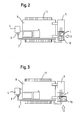
- Figure 3 shows the systematic top view of an inventive Embodiment in which the loading of the hopper 14 of the concrete pump 1 from the side.
- the arrangement of the concrete pump 1 in the rear area 12 of the superstructure 9 has the following advantages: Compared to the heavy tower 4 with the drilling drive and the drilling tool, it represents an additional counterweight and thereby improves the stability of the drilling device. This is particularly useful if the continuous auger is difficult to pull during concreting and thus high tensile forces have to be activated. Another advantage is that an essentially fixed-installed concrete delivery line 2 is led from the outlet opening 3 of the concrete pump 1 to a transfer point 8 fixedly attached to the mast. This has the advantage that there is no danger for the concreting line between the concrete pump and concreting head 14 when the drilling device is being moved or when the drilling process is being performed.
- the concrete delivery line 2 is short, cannot kink and cannot be damaged by the chain undercarriage when driving to the next drilling starting point.
- the concrete delivery line 2 makes essentially the same movements as the superstructure 9 when it is rotated or moved.
- Another advantage of the device combination according to the invention is that on a separate operating personnel Concrete pump 1 can be dispensed with. By the immediate Close to the concrete pump 1 to the excavator driver, it is possible for this to monitor the filling process during concreting. The excavator driver can directly contact the driver of the concrete delivery vehicle take up.
- the concreting lines 2 laid essentially in a straight line along the superstructure 9 and the tower 4 mean less Resistance when pumping the concrete and reduce the Susceptibility to blockages. Furthermore, they can essentially rectilinear connections largely in the form of tubular steel be trained on what is the friction in concrete delivery Rubber hoses reduced.
- Peristaltic pumps are another variant. With these Pumping is essentially the delivery of the concrete in that the concrete by squeezing elastic Hoses are moved forward within the hose line.
- Screw pumps or progressing cavity pumps can be used.
- the hopper through which the concrete pump 1 is fed can, as shown in Figure 1, on the rear of the superstructure 9 may be arranged, the mixing vehicles then transverse to Approach the upper axle longitudinal axis to the drill.
- a further variant is the filling opening of the concrete pump 1 arranged so that the extended in the direction of Rear of the superstructure 9 has.
- Figure 2 shows the systematic Top view of an embodiment according to the invention, at which the loading of the hopper 16 of the concrete pump 1 of done in the back.
- the area 15 is fixed so that when swiveling the uppercarriage 9 does not come into contact with the chains of the undercarriage 11. in the In principle, a floor clearance of the pump is sufficient in the area Decimeters to compensate for uneven terrain.
Landscapes
- Engineering & Computer Science (AREA)
- Structural Engineering (AREA)
- General Engineering & Computer Science (AREA)
- Life Sciences & Earth Sciences (AREA)
- General Life Sciences & Earth Sciences (AREA)
- Mining & Mineral Resources (AREA)
- Paleontology (AREA)
- Civil Engineering (AREA)
- Earth Drilling (AREA)
- On-Site Construction Work That Accompanies The Preparation And Application Of Concrete (AREA)
- Nitrogen And Oxygen Or Sulfur-Condensed Heterocyclic Ring Systems (AREA)
Abstract
Description
- Bohrverfahren mit durchgehenden, langen Bohrschnecken;
- Verdrängungsbohrverfahren, bei denen im Wesentlichen lange Rohre in den Boden gedreht oder gerammt werden, wobei der anstehende Boden zur Seite verdrängt wird;
- Verfahren, bei denen lange Bohrschnecken mit einem drehbaren Hüllrohr umgeben sind, wobei sowohl Schnecke als Rohr gleichzeitig in den Boden eingebracht werden.
Gegenüber dem schweren Turm 4 mit dem Bohrantrieb und dem Bohrwerkzeug stellt sie ein zusätzliches Gegengewicht dar und verbessert dadurch die Standsicherheit des Bohrgerätes. Dies ist insbesondere dann von Nutzen, wenn die durchgehende Bohrschnecke während des Betonierens schwer zu ziehen ist und somit hohe Zugkräfte zu aktivieren sind. Ein weiterer Vorteil liegt darin, dass von der Austrittsöffnung 3 der Betonpumpe 1 eine im Wesentlichen festverlegte Betonförderleitung 2 bis zu einem fest am Mast befestigten Übergabepunkt 8 geführt wird. Dies hat den Vorteil, dass beim Verfahren des Bohrgerätes bzw. beim reinen Bohrvorgang keine Gefahr für die Betonierleitung zwischen Betonpumpe und Betonierkopf 14 besteht. Die Betonförderleitung 2 ist kurz, kann nicht knicken und nicht vom Kettenfahrwerk beim Fahren zum nächsten Bohransatzpunkt beschädigt werden. Die Betonförderleitung 2 macht im Wesentlichen die gleichen Bewegungen mit wie der Oberwagen 9, wenn er gedreht oder verfahren wird.
Claims (11)
- Bohrvorrichtung zur Herstellung eines Betonelementes im Boden mit einem Fahrzeug, an welchem ein Turm (4), eine Betonpumpe (1) und ein Bohrwerkzeug angeordnet sind, welches zum Einbringen in den Boden am Turm (4) gelagert ist, wobei mittels der Betonpumpe (1) und einer Förderleitung (2), in einen vom Bohrwerkzeug gebildeten Hohlraum Beton zum Bilden des Betonelementes pumpbar ist,
dadurch gekennzeichnet , dass am Heckbereich (12) des Fahrzeuges, welches einem Frontbereich mit dem Turm (4) gegenüberliegt, die Betonpumpe (1) lösbar gehaltert ist. - Bohrvorrichtung nach Anspruch 1,
dadurch gekennzeichnet , dass der Antrieb der Betonpumpe (1) über ein zusätzlich am Fahrzeug angebrachtes Hydraulikpumpenaggregat (5) mit eigenem Antrieb erfolgt und/oder dass der Antrieb der Betonpumpe (1) über die fahrzeugeigenen Hydraulikpumpen erfolgt. - Bohrvorrichtung nach Anspruch 1 oder 2,
dadurch gekennzeichnet, dass am Fahrzeug, bevorzugterweise auf der dem Turm (4) gegenüberliegenden Seite, ein Wasserbehälter (7) angeordnet ist. - Bohrvorrichtung nach einem der Ansprüche 1 bis 3,
dadurch gekennzeichnet , dass die Betonpumpe (1) über eine Haltevorrichtung (6) lösbar mit dem Fahrzeug verbunden ist. - Bohrvorrichtung nach einem der Ansprüche 1 bis 4,
dadurch gekennzeichnet , dass von einem fest am Turm (4) befestigten Übergabepunkt (8) eine bewegliche Schlauchleitung (13) zum Betonierkopf (14) am luftseitigen Ende des Bohrwerkzeuges geführt ist. - Bohrvorrichtung nach einem der Ansprüche 1 bis 5,
dadurch gekennzeichnet , dass die Betonpumpe (1) eine Einfach- oder Mehrfachkolbenpumpe, eine Schlauchpumpe, eine Schneckenpumpe oder eine Exzenterschneckenpumpe ist. - Bohrvorrichtung nach einem der Ansprüche 1 bis 6,
dadurch gekennzeichnet , dass die Betonpumpe hydraulisch angetrieben ist. - Bohrvorrichtung nach einem der Ansprüche 1 bis 7,
dadurch gekennzeichnet , dass das Bohrwerkzeug eine einfache Bohrschnecke, eine Bohrschnecke mit drehbaren Hüllrohren oder ein Verdrängungsbohrwerkzeug ist. - Bohrvorrichtung nach einem der Ansprüche 1 bis 8,
dadurch gekennzeichnet, dass die Betonpumpe (1) einen Zugabetrichter (16) aufweist. - Bohrvorrichtung nach einem der Ansprüche 1 bis 9,
dadurch gekennzeichnet , dass das Fahrzeug einen Oberwagen (9) aufweist, der gegenüber einem Unterwagen (11) drehbar ist, und dass die Betonpumpe (1) am Oberwagen (9) angehängt ist. - Bohrvorrichtung nach einem der Ansprüche 1 bis 10,
dadurch gekennzeichnet , dass zur Erleichterung des Befüllens mit Beton die Betonpumpe (1) versetzt zum Oberwagen (9) in einem bodennahen Bereich angeordnet ist.
Applications Claiming Priority (2)
| Application Number | Priority Date | Filing Date | Title |
|---|---|---|---|
| DE10238193A DE10238193B4 (de) | 2002-08-21 | 2002-08-21 | Bohrvorrichtung |
| DE10238193 | 2002-08-21 |
Publications (3)
| Publication Number | Publication Date |
|---|---|
| EP1391561A2 true EP1391561A2 (de) | 2004-02-25 |
| EP1391561A3 EP1391561A3 (de) | 2005-11-23 |
| EP1391561B1 EP1391561B1 (de) | 2009-04-01 |
Family
ID=7714847
Family Applications (1)
| Application Number | Title | Priority Date | Filing Date |
|---|---|---|---|
| EP03016166A Expired - Lifetime EP1391561B1 (de) | 2002-08-21 | 2003-07-16 | Bohrvorrichtung |
Country Status (3)
| Country | Link |
|---|---|
| US (1) | US7306405B2 (de) |
| EP (1) | EP1391561B1 (de) |
| DE (3) | DE10238193B4 (de) |
Cited By (1)
| Publication number | Priority date | Publication date | Assignee | Title |
|---|---|---|---|---|
| CN111994647A (zh) * | 2020-09-02 | 2020-11-27 | 界首市金龙机械设备有限公司 | 一种智能机器人翻仓机 |
Families Citing this family (11)
| Publication number | Priority date | Publication date | Assignee | Title |
|---|---|---|---|---|
| US20080131211A1 (en) * | 2004-07-13 | 2008-06-05 | Nesmith Willie M | Installation effort deep foudnation method |
| ITTO20050347A1 (it) * | 2005-05-20 | 2006-11-21 | Solmec S P A | Attrezzatura di scavo e costipazione per la costruzione di pali |
| US7581903B1 (en) | 2006-06-08 | 2009-09-01 | Thermoforte, Inc. | Method of manufacture and installation flowable thermal backfills |
| FR2944299B1 (fr) * | 2009-04-10 | 2016-08-26 | Cie Du Sol | Machine d'excavation de sol du type fraise munie d'un chariot mobile |
| PL2295645T3 (pl) * | 2009-08-28 | 2012-09-28 | Bauer Maschinen Gmbh | Narzędzie wiertnicze |
| FR3026754B1 (fr) * | 2014-10-01 | 2016-12-02 | Soletanche Freyssinet | Machine et procede pour la realisation de colonnes dans un sol |
| JP6296199B1 (ja) * | 2016-11-17 | 2018-03-20 | Jfeスチール株式会社 | ハット形鋼矢板及び壁体 |
| CN108729447A (zh) * | 2018-07-18 | 2018-11-02 | 中铁十六局集团第三工程有限公司 | 一种具有改进型连接弯管的cfg桩机及其施工方法 |
| CN109098178A (zh) * | 2018-09-28 | 2018-12-28 | 中国电建市政建设集团有限公司 | 一种混凝土灌注设备 |
| CN113914397B (zh) * | 2021-11-25 | 2022-11-04 | 中冶成都勘察研究总院有限公司 | 一种用于松散填土层的注浆孔引孔装置 |
| EP4497873B1 (de) * | 2023-07-27 | 2025-10-29 | BAUER Maschinen GmbH | Vorrichtung und verfahren zum bilden eines bodenelementes |
Citations (1)
| Publication number | Priority date | Publication date | Assignee | Title |
|---|---|---|---|---|
| US5967700A (en) | 1995-12-04 | 1999-10-19 | Gunther; Johan M. | Lime/cement columnar stabilization of soils |
Family Cites Families (19)
| Publication number | Priority date | Publication date | Assignee | Title |
|---|---|---|---|---|
| US3255592A (en) * | 1961-05-01 | 1966-06-14 | Herman L Moor | Control system for discharging concrete grout to form piles |
| FR1595399A (de) * | 1967-01-08 | 1970-06-08 | ||
| US3645343A (en) * | 1970-05-11 | 1972-02-29 | Gordon E Mays | Rotary drilling machine |
| US3682575A (en) * | 1970-12-10 | 1972-08-08 | Karl Guddal | Concrete pump |
| GB2042029B (en) * | 1979-02-13 | 1982-11-17 | Chuan Pao Chen P | Method and apparatus for forming subterranean concrete piles |
| JPS5631928A (en) * | 1979-08-20 | 1981-03-31 | Ryoji Morita | Constructing method for soil pile |
| US4397588A (en) * | 1981-01-23 | 1983-08-09 | Vibroflotation Foundation Company | Method of constructing a compacted granular or stone column in soil masses and apparatus therefor |
| US4428677A (en) * | 1982-04-02 | 1984-01-31 | Concrete Transport Mixer Co. | Hopper for mixer unit of a concrete transport vehicle |
| US4846580A (en) * | 1987-03-20 | 1989-07-11 | Rotec Industries, Inc. | Large scale concrete conveyance techniques |
| NL8802318A (nl) * | 1988-09-19 | 1990-04-17 | Ballast Nedam Groep Nv | Werkwijze voor het vervaardigen van een paalfundering en bouwwerk omvattende een dergelijke paalfundering. |
| US5256005A (en) * | 1989-07-13 | 1993-10-26 | Beck Iii August H | Method and apparatus for placing cementitious materials in earth excavations |
| AT398323B (de) * | 1992-06-10 | 1994-11-25 | Elin Energieversorgung | Einrichtung zum rammen einer fundierung vorzugsweise für einen mast |
| JP3247757B2 (ja) * | 1993-03-11 | 2002-01-21 | 広和産業株式会社 | セメントミルク注入式のダウンホールハンマー |
| US5512325A (en) * | 1994-10-28 | 1996-04-30 | Indresco Inc. | Non-slumping, pumpable castable and method of applying the same |
| GB2328700B (en) * | 1995-07-31 | 1999-04-14 | Kvaerner Cementation Found Ltd | Improved auger piling |
| US5697733A (en) * | 1996-01-11 | 1997-12-16 | Marsh, Jr.; Richard O. | Centrifugal force vibration apparatus and system |
| US6048137A (en) * | 1996-10-31 | 2000-04-11 | Beck, Iii; August H. | Drilled, cast-in-place shell pile and method of constructing same |
| US6957930B2 (en) * | 1999-09-01 | 2005-10-25 | Landau Richard E | Apparatus to form columns of granular material |
| US6485234B2 (en) * | 2000-12-12 | 2002-11-26 | Condon-Johnson & Associates, Inc. | Apparatus and method for making cylindrical columns |
-
2002
- 2002-08-21 DE DE10238193A patent/DE10238193B4/de not_active Expired - Fee Related
-
2003
- 2003-03-26 DE DE20304831U patent/DE20304831U1/de not_active Expired - Lifetime
- 2003-07-16 DE DE50311365T patent/DE50311365D1/de not_active Expired - Lifetime
- 2003-07-16 EP EP03016166A patent/EP1391561B1/de not_active Expired - Lifetime
- 2003-08-18 US US10/642,156 patent/US7306405B2/en not_active Expired - Lifetime
Patent Citations (1)
| Publication number | Priority date | Publication date | Assignee | Title |
|---|---|---|---|---|
| US5967700A (en) | 1995-12-04 | 1999-10-19 | Gunther; Johan M. | Lime/cement columnar stabilization of soils |
Cited By (1)
| Publication number | Priority date | Publication date | Assignee | Title |
|---|---|---|---|---|
| CN111994647A (zh) * | 2020-09-02 | 2020-11-27 | 界首市金龙机械设备有限公司 | 一种智能机器人翻仓机 |
Also Published As
| Publication number | Publication date |
|---|---|
| DE50311365D1 (de) | 2009-05-14 |
| US20040037652A1 (en) | 2004-02-26 |
| US7306405B2 (en) | 2007-12-11 |
| EP1391561A3 (de) | 2005-11-23 |
| DE10238193A1 (de) | 2004-03-04 |
| EP1391561B1 (de) | 2009-04-01 |
| HK1063648A1 (zh) | 2005-01-07 |
| DE20304831U1 (de) | 2003-06-12 |
| DE10238193B4 (de) | 2004-08-19 |
Similar Documents
| Publication | Publication Date | Title |
|---|---|---|
| DE10238193B4 (de) | Bohrvorrichtung | |
| DE4335753C2 (de) | Hydraulisch angetriebener Abbaubagger für eine Vortriebseinrichtung zum unterirdischen Vortrieb | |
| DE2925505A1 (de) | Vortriebsschild | |
| EP2534310B1 (de) | Verfahren zur herstellung von materialsäulen und rüttlervorrichtung mit einer hubeinheit | |
| DE2108591A1 (de) | Einrichtung und Verfahren zur Durchfuh rung des Schildbauweise fur die Errichtung von Tunnels oder Stollen | |
| DE3726472C2 (de) | ||
| EP3513039B1 (de) | Messsignalauswertungsverfahren | |
| DE202010017629U1 (de) | Verbaueinrichtung | |
| DE10325576A1 (de) | Vorderteil zum Erdbohren und Erdbohrmaschine | |
| EP0213259B1 (de) | Nachträgliche Deponieabdichtung | |
| AT352774B (de) | Vorrichtung zum abbau und ausbringen des boden- materials bei rohrvortrieben | |
| DE3410830C2 (de) | ||
| DE69304486T2 (de) | Verbesserte Bodenbearbeitungsvorrichtung mit rotierenden Strahlen | |
| DE3204564C2 (de) | Vorrichtung zum Auffahren eines Stollens, Tunnels oder dergleichen im Rohrvorpreßbetrieb, insbesondere zur Herstellung einer nicht begehbaren Rohrleitung | |
| EP0346941B1 (de) | Verfahren zum Herstellen von Bauelementen im Baugrund, wie Pfählen, Ankern oder dergleichen, sowie Vorrichtung zur Ausführung dieses Verfahrens | |
| DE3208492A1 (de) | Verfahren und vorrichtung zum einbringen von hohlpfaehlen in den boden | |
| DE3249087C2 (de) | Vorrichtung zum Auffahren eines Stollens, Tunnels oder dergleichen im Rohrvorpreßbetrieb, insbesondere zur Herstellung einer nicht begehbaren Rohrleitung | |
| DE1811449B2 (de) | Raeum- und foerdereinrichtung zum grabenlosen verlegen von betonrohren mittels des rohrdurchpressverfahrens | |
| DE1758505C (de) | Bohrend arbeitende Vortriebsmaschine zum Auffahren horizontal, geneigt oder vertikal verlaufender Grubenbaue | |
| DE19749771C1 (de) | Verfahren zum Einbringen von Gleit- und Füllmittel beim grabenlosen Verlegen von Versorgungsleitungen und Vorrichtung zur Durchführung des Verfahrens | |
| DE1920322B2 (de) | Vorri chtung zum loesen und laden des anstehenden erdreichs beim rohrvorpressen | |
| DE19713737C2 (de) | Verfahren und Vorrichtung zum Ausbau eines Erdkerns aus einem grabenlos verlegten Rohr | |
| WO2024223182A1 (de) | Tunnelbohrmaschine und verfahren zum anfahren einer tunnelbohrmaschine | |
| DE1484448A1 (de) | Verdraengungsbohrgeraet,gleichzeitig als Bohrgeraet und Fuellgutschuettrohr mit nochmaliger Bodenverdraengung beim Verfuellen,zum Herstellen von Ortbetonpfaehlen,Bodenverfestigungen und zum Heben von Strassenfahrbahnplatten | |
| CH690654A5 (de) | Bohrvorrichtung für die Erstellung von Rohrleitungen, vorzugsweise von Kanalisationsrohren. |
Legal Events
| Date | Code | Title | Description |
|---|---|---|---|
| PUAI | Public reference made under article 153(3) epc to a published international application that has entered the european phase |
Free format text: ORIGINAL CODE: 0009012 |
|
| AK | Designated contracting states |
Kind code of ref document: A2 Designated state(s): AT BE BG CH CY CZ DE DK EE ES FI FR GB GR HU IE IT LI LU MC NL PT RO SE SI SK TR |
|
| AX | Request for extension of the european patent |
Extension state: AL LT LV MK |
|
| REG | Reference to a national code |
Ref country code: HK Ref legal event code: DE Ref document number: 1063648 Country of ref document: HK |
|
| PUAL | Search report despatched |
Free format text: ORIGINAL CODE: 0009013 |
|
| AK | Designated contracting states |
Kind code of ref document: A3 Designated state(s): AT BE BG CH CY CZ DE DK EE ES FI FR GB GR HU IE IT LI LU MC NL PT RO SE SI SK TR |
|
| AX | Request for extension of the european patent |
Extension state: AL LT LV MK |
|
| 17P | Request for examination filed |
Effective date: 20060515 |
|
| AKX | Designation fees paid |
Designated state(s): DE GB IT |
|
| 17Q | First examination report despatched |
Effective date: 20080730 |
|
| GRAP | Despatch of communication of intention to grant a patent |
Free format text: ORIGINAL CODE: EPIDOSNIGR1 |
|
| GRAS | Grant fee paid |
Free format text: ORIGINAL CODE: EPIDOSNIGR3 |
|
| GRAA | (expected) grant |
Free format text: ORIGINAL CODE: 0009210 |
|
| AK | Designated contracting states |
Kind code of ref document: B1 Designated state(s): DE GB IT |
|
| REG | Reference to a national code |
Ref country code: GB Ref legal event code: FG4D Free format text: NOT ENGLISH |
|
| REF | Corresponds to: |
Ref document number: 50311365 Country of ref document: DE Date of ref document: 20090514 Kind code of ref document: P |
|
| REG | Reference to a national code |
Ref country code: HK Ref legal event code: GR Ref document number: 1063648 Country of ref document: HK |
|
| PLBE | No opposition filed within time limit |
Free format text: ORIGINAL CODE: 0009261 |
|
| STAA | Information on the status of an ep patent application or granted ep patent |
Free format text: STATUS: NO OPPOSITION FILED WITHIN TIME LIMIT |
|
| 26N | No opposition filed |
Effective date: 20100105 |
|
| PGFP | Annual fee paid to national office [announced via postgrant information from national office to epo] |
Ref country code: DE Payment date: 20130730 Year of fee payment: 11 |
|
| REG | Reference to a national code |
Ref country code: DE Ref legal event code: R119 Ref document number: 50311365 Country of ref document: DE |
|
| PG25 | Lapsed in a contracting state [announced via postgrant information from national office to epo] |
Ref country code: DE Free format text: LAPSE BECAUSE OF NON-PAYMENT OF DUE FEES Effective date: 20150203 |
|
| REG | Reference to a national code |
Ref country code: DE Ref legal event code: R119 Ref document number: 50311365 Country of ref document: DE Effective date: 20150203 |
|
| PGFP | Annual fee paid to national office [announced via postgrant information from national office to epo] |
Ref country code: GB Payment date: 20160627 Year of fee payment: 14 |
|
| PGFP | Annual fee paid to national office [announced via postgrant information from national office to epo] |
Ref country code: IT Payment date: 20160721 Year of fee payment: 14 |
|
| GBPC | Gb: european patent ceased through non-payment of renewal fee |
Effective date: 20170716 |
|
| PG25 | Lapsed in a contracting state [announced via postgrant information from national office to epo] |
Ref country code: GB Free format text: LAPSE BECAUSE OF NON-PAYMENT OF DUE FEES Effective date: 20170716 |
|
| PG25 | Lapsed in a contracting state [announced via postgrant information from national office to epo] |
Ref country code: IT Free format text: LAPSE BECAUSE OF NON-PAYMENT OF DUE FEES Effective date: 20170716 |