EP1389659B1 - Dispositif de nettoyage pour surfaces exposées aux intempéries - Google Patents
Dispositif de nettoyage pour surfaces exposées aux intempéries Download PDFInfo
- Publication number
- EP1389659B1 EP1389659B1 EP03018007A EP03018007A EP1389659B1 EP 1389659 B1 EP1389659 B1 EP 1389659B1 EP 03018007 A EP03018007 A EP 03018007A EP 03018007 A EP03018007 A EP 03018007A EP 1389659 B1 EP1389659 B1 EP 1389659B1
- Authority
- EP
- European Patent Office
- Prior art keywords
- cleaning device
- layers
- preceding patent
- spacers
- layer
- Prior art date
- Legal status (The legal status is an assumption and is not a legal conclusion. Google has not performed a legal analysis and makes no representation as to the accuracy of the status listed.)
- Expired - Lifetime
Links
- 238000004140 cleaning Methods 0.000 title claims abstract description 127
- 125000006850 spacer group Chemical group 0.000 claims abstract description 65
- XLYOFNOQVPJJNP-UHFFFAOYSA-N water Substances O XLYOFNOQVPJJNP-UHFFFAOYSA-N 0.000 claims abstract description 34
- RYGMFSIKBFXOCR-UHFFFAOYSA-N Copper Chemical compound [Cu] RYGMFSIKBFXOCR-UHFFFAOYSA-N 0.000 claims abstract description 21
- 239000010949 copper Substances 0.000 claims abstract description 19
- 229910052802 copper Inorganic materials 0.000 claims abstract description 19
- 230000000844 anti-bacterial effect Effects 0.000 claims abstract description 4
- 150000001875 compounds Chemical class 0.000 claims abstract description 4
- 230000000855 fungicidal effect Effects 0.000 claims abstract description 4
- 230000000694 effects Effects 0.000 claims description 9
- 238000004080 punching Methods 0.000 claims description 9
- 239000004033 plastic Substances 0.000 claims description 8
- 239000000463 material Substances 0.000 claims description 7
- 239000011324 bead Substances 0.000 claims description 6
- 230000009471 action Effects 0.000 claims description 4
- 239000004744 fabric Substances 0.000 claims description 3
- 239000000853 adhesive Substances 0.000 claims description 2
- 230000001070 adhesive effect Effects 0.000 claims description 2
- 239000011888 foil Substances 0.000 claims description 2
- 239000008187 granular material Substances 0.000 claims description 2
- 238000005096 rolling process Methods 0.000 claims description 2
- 238000007688 edging Methods 0.000 claims 1
- 239000008188 pellet Substances 0.000 claims 1
- 230000000149 penetrating effect Effects 0.000 claims 1
- 230000000717 retained effect Effects 0.000 claims 1
- 238000006243 chemical reaction Methods 0.000 abstract description 10
- 239000010410 layer Substances 0.000 description 152
- 238000013461 design Methods 0.000 description 7
- 239000002184 metal Substances 0.000 description 6
- 229910052751 metal Inorganic materials 0.000 description 6
- 238000003860 storage Methods 0.000 description 6
- 238000004519 manufacturing process Methods 0.000 description 5
- 238000000034 method Methods 0.000 description 5
- 239000000126 substance Substances 0.000 description 5
- 239000011449 brick Substances 0.000 description 3
- 238000001704 evaporation Methods 0.000 description 3
- 230000008020 evaporation Effects 0.000 description 3
- 239000011521 glass Substances 0.000 description 3
- 239000007788 liquid Substances 0.000 description 3
- 238000012549 training Methods 0.000 description 3
- 230000008901 benefit Effects 0.000 description 2
- 230000015572 biosynthetic process Effects 0.000 description 2
- 239000007795 chemical reaction product Substances 0.000 description 2
- 239000011889 copper foil Substances 0.000 description 2
- 238000002474 experimental method Methods 0.000 description 2
- 230000002349 favourable effect Effects 0.000 description 2
- 230000006872 improvement Effects 0.000 description 2
- 230000008569 process Effects 0.000 description 2
- 230000005855 radiation Effects 0.000 description 2
- 239000002356 single layer Substances 0.000 description 2
- 238000012546 transfer Methods 0.000 description 2
- 241000272525 Anas platyrhynchos Species 0.000 description 1
- 238000005452 bending Methods 0.000 description 1
- 230000009286 beneficial effect Effects 0.000 description 1
- 239000003795 chemical substances by application Substances 0.000 description 1
- 238000009833 condensation Methods 0.000 description 1
- 230000005494 condensation Effects 0.000 description 1
- 238000010276 construction Methods 0.000 description 1
- 239000000428 dust Substances 0.000 description 1
- 239000000835 fiber Substances 0.000 description 1
- 238000010304 firing Methods 0.000 description 1
- 239000012530 fluid Substances 0.000 description 1
- 238000011010 flushing procedure Methods 0.000 description 1
- 230000004907 flux Effects 0.000 description 1
- 230000001976 improved effect Effects 0.000 description 1
- 238000002955 isolation Methods 0.000 description 1
- 238000005304 joining Methods 0.000 description 1
- 239000008239 natural water Substances 0.000 description 1
- 230000035699 permeability Effects 0.000 description 1
- 230000035484 reaction time Effects 0.000 description 1
- 239000005060 rubber Substances 0.000 description 1
- 238000007493 shaping process Methods 0.000 description 1
- 239000010454 slate Substances 0.000 description 1
- 238000003892 spreading Methods 0.000 description 1
- 230000007480 spreading Effects 0.000 description 1
- 230000037303 wrinkles Effects 0.000 description 1
Images


Classifications
-
- E—FIXED CONSTRUCTIONS
- E04—BUILDING
- E04D—ROOF COVERINGS; SKY-LIGHTS; GUTTERS; ROOF-WORKING TOOLS
- E04D13/00—Special arrangements or devices in connection with roof coverings; Protection against birds; Roof drainage ; Sky-lights
- E04D13/002—Provisions for preventing vegetational growth, e.g. fungi, algae or moss
Definitions
- the invention relates to a cleaning device for applying on a surface exposed to the weather, in particular a roof, a roof surface, a solar system surface or a facade, wherein the device has a Has a variety of reaction surfaces arranged in layers are and a metallic, preferably copper-containing, Have surface, which in conjunction with Water-cleaning, preferably fungicidal and / or bactericidal, producing compounds that dissolved in water at least partially wet the roof.
- the utility model DE 201 04 999 U1 pointed out.
- This utility model also discloses a metallic roof ridge element, which preferably is made of copper sheets, with over the length of the roof ridge element is a chamber which is on the bottom by a through Sheet is limited and has a grid on the outside, which achieve a surface-enlarging effect should. Due to the symmetrical design of the Firstiatas will be on both sides of the roof respectively a chamber formed according to that described there The idea of the invention also by a moisture-storing Fleece or braid can be filled. practical Experiments with such a design of a ridge hood have shown that in the thus formed chamber there is no sufficient storage volume, and on top of that the storage time for natural water extremely low is because a much too early evaporation eventual Moisture occurs.
- the inventor has realized that to improve self-cleaning Effect of cleaning devices for application on a surface exposed to the weather it essential is, an optimal combination between the trapped and stored humidity and the available Asked reaction surface of the metal, in particular the Copper, which is necessary, in addition to take care wear is that also a sufficient drainage possibility the liquid stored in the meantime necessary is as soon as a new water supply, so new rain, occurs. It also seems essential that the Embodiment of the cleaning device, in particular the Chambers in which the moisture is recovered, so can be designed that the outside impinging solar radiation the inner chambers are not too much warmed to one early evaporation of moisture from the chambers too avoid.
- the inventor proposes the per se known Cleaning device for applying to a weather exposed surface, in particular a roof, a roof surface, a solar system surface or a facade, to improve, the cleaning device a variety of reaction surfaces arranged in layers are and a metallic, preferably copper-containing Having surface which cleans in conjunction with water, preferably fungicidal and / or bactericidal compounds generate that dissolved in the water at least the roof can partially wet.
- the improvement lies in that at least one upper layer, one lower layer Position and at least one intermediate layer are provided, wherein at least two layers at least over a partial area their area separated by spacers are that spaces are formed between the layers in which natural moisture, especially rainwater, tile in and can be rinsed out again.
- the occurring water is targeted to multiple levels of moisture through Spacers are formed distributed, with the in these Chambers stored moisture due to the above lying layers, for example, by sunlight relative little is heated, especially if the spacers the neighboring area only touches almost point-like, allowing the stored moisture sufficient time for Is made available with the metallic, preferably latticed surface, to respond and for the cleansing Effect necessary substances from the metallic Surface, which forms the reaction surface to dissolve.
- the inventive design that with newly occurring water one possible unimpeded flushing of these chambers takes place, so that the substances formed there freely to the outside can be washed and on the surface to be cleaned to be effective.
- the outer layer with a variety provided by breakthroughs, so that too on the surface the cleaning device incident rain relative unhindered to the bottom of each layer can penetrate. Accordingly, not only the outer one Location but also the underlying layers and possibly even the lower layer with breakthroughs be provided in order to produce a permeability there, however, the breakthroughs should be sufficiently small should be for easy shooting through of liquid too prevent. So there has to be a compromise between storage effect and obstruction of the flow of fluid be achieved.
- the individual layers to each other be arranged parallel or conical, wherein it is particularly advantageous if the distance between enlarged the individual layers upwards.
- Advantageous It is definitely when the area is out of the Sum of the inlet openings is greater than the area of Sum of the outlet openings.
- the spacers between the layers can, for example be designed so that they are as punctiform or at most in a line the areas to be kept apart It should be noted that it is the spacers are not necessarily separate Elements must act, but that the layers described can be produced by punching tools and this by appropriate shaping of the surface and optionally Cut out the openings of the spacers integrated into the surface of the individual layers can.
- the shape of the spacers is here barely set a limit, but it is advantageous if in each case the highest possible increase in the reactive Surface is satisfied by such spacers.
- Such Training allows you to overlay several layers wherein the formed beads each arranged above Protect the situation from slipping, respectively if provided between the layers of a hinge is, even a folding of the individual layers allows becomes. Since the cleaning device according to the invention the outer Weather and thus pollution by Dust or deposit of leaves of nearby trees exposed, it may be advantageous to the individual layers take apart or unfold and thus carry out a cleaning in the intermediate areas to be able to. In addition, the possibility arises through a conical opening of the individual layers also a Schneerisonêt to produce, once on a sloping Roof lying snow sets in motion, so this one by spreading layers of the cleaning device is slowed down.
- the cleaning device according to the invention can be adapted to the most diverse forms of roofs and surfaces, wherein, for example, such a cleaning device can also be designed as a roof ridge or Dachfirstabdeckung.
- the contour and / or the surface of the cleaning device can be adapted to the contours and / or surfaces of known roof tiles and roof tiles.
- the website www.braas.de or www.creaton.de is an example.
- roof cleaning device of the type mentioned can also be used on thatched roofs or roofs that are covered with slate, roofing felt, Welleternitplatten or the like, in particular, an application for solar systems or other glass or Kunststoffbedachitch is possible.
- the cleaning device only one intermediate layer, so a total of three Has layers.
- the distances of the Single layers not to keep the same, but different to create high spaces, so that as possible optimal water retention depending on the given weather conditions certain regions.
- a further improvement in the effectiveness of the cleaning device can be achieved in that of the The layers formed spaces, copper material with greatly enlarged Surface, preferably granules and / or Flakes and / or braid and / or casings and / or fibers made of copper and / or sintered pieces are arranged.
- surface enlarging agent is the reaction surface provided greatly expanded, allowing a greater effectiveness of the cleaning device is possible.
- the individual layers can be laterally and / or vertically offset be arranged to each other.
- the layers can two opposite ends up and / or bends exhibit.
- the layers can be individually loose or at least the outer and lower layers, preferably all Layers to be interconnected using known joining techniques like screws, nails, rivets, welded joints or adhesive joints are applicable.
- At least the lower layer, preferably all layers, the three-dimensional Surface shape of roof sections and / or Roof tiles and / or solar systems or other of the weather exposed surfaces are adjusted.
- Attachment of the cleaning device can at least the lower layer fasteners and / or mounting brackets exhibit.
- Such fasteners can at least partially made of plastic and in at least one of the layers, preferably the lower layer, clipped be equipped.
- this formed braid and / or tissue-like are, so that the layers are resilient to each other Keeping a distance and at the same time as possible low heat fluxes between the individual layers arise.
- these layers can be produced in one piece be here preferably by bending and Fold the corresponding spaces are generated.
- the individual layers of the cleaning device can on the one hand made of thin sheet metal, preferably copper sheet
- a film preferably a copper foil to form. If all layers of the cleaning device are formed from films, so this has the advantage that the layers are very simply the outer contour of each covered tile to adjust.
- films of thin sheets do not differ.
- the framework of the Invention also attributable to a film or layer that made is built up of several layers, not necessarily all Layers must be metallic, but only the The moisture-accessible layer must be metallic Have property to produce the cleaning effect.
- the cleaning device with at least one layer preferably equipped with all layers in the area Elevations and depressions are impressed, preferably This can be done by punching, in particular by rolling rollers.
- punching in particular by rolling rollers.
- Production of the cleaning device according to the invention particularly advantageous by at least one punching operation can be.
- a film may also be a braid or tissue can be used as a layer without the scope of To leave invention.
- a braid or tissue can be used as a layer without the scope of To leave invention.
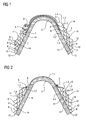
- FIG. 1 shows a cleaning device according to the invention for placing on a roof ridge tile 3.
- the cleaning device consists of four layers 1.1 - 1.4, which is the Largely embracing roof ridge tiles 3 on the top, Each layer is over both sides of the roof ridge tile extends.
- the individual layers have this punched Bulges 2 on, as a spacer between the act individual layers.
- At the bottom of each Layers are bulges 8 bent up, against which each overlying layer can support with its long side. Due to the design of the individual layers with the illustrated Spacers will be sufficient between the layers Rooms 14 generated in the rain or condensation of penetrate above openings 6 in the layers and in can collect the gaps.
- the layers are like that designed that due to the spacers only a very low thermal contact exists between them, so that too solar radiation does not cause a quick evaporation of lying in the spaces 14 water Leads, giving enough time and surface to training the chemical substances available to the Lead roof cleaning.
- FIG. 2 shows a similar cleaning device 1 a Dachfirstziegel 3, but here is only the lower Layer 1.4 designed so that it covers the entire roof ridge tile 3, while the further arranged thereon Layers 1.1 - 1.3 arranged exclusively on the side are and by fasteners 5 in the form of screws, Nails, rivets or the like prevented from slipping off become.
- the design of the individual layers corresponds essentially the representation of Figure 1, wherein also here in addition between the layers deposits, for example Copper grains, casts, sintered elements, braids or the like introduced into the spaces 14 between the layers can be.
- FIGS. 3 and 4 show two cleaning devices 1, which are arranged on flat roof tiles 9, wherein these also formed 4-ply.
- the equipment of the layers corresponds to the figures 1 or 2, again here Intermediate spaces 14 between the individual layers 1.1 - 1.4 are generated in which store moisture can.
- FIG. 4 shows a variation of the layers with regard to their Spacer in that the first one below Position 1.1 is executed, has spacers 2, which are made of good insulating plastic, so that between the lower layer 1.4 and the overlying Location 1.3 only low thermal contact exists. This will also heat through the underlying Brick as little as possible introduced into the overlying layers. Similarly, the outer layer 1.1 of the underneath lying intermediate layer 1.2 also by clipped, made of plastic spacers separated.
- the cleaning devices shown in this document represent only selected examples, with the simpler Representation also chosen simple geometric shapes were. On the one hand, this affects the surface the rest of the cleaning devices, as well as the Structure and shape of the spacers, of course different by appropriately trained punch can be executed, with very different Forms can be used. It is advantageous here usually when at least the lower layer of each form the covered surface, especially the underlying Adapts bricks, although it does may be partially advantageous when using spacers opposite the underlying surface to be cleaned is working. The design of the spacers even if formed from the individual layers themselves can be particularly beneficial if they add too much extra Lead surfaces and at the same time as possible a low heat transfer to be kept in the distance Create next location.
- FIGS. 5a to 5d show cross sections through possible ones Contours of the cleaning device. This is how the contour corresponds FIG. 5a, for example, of a Frankfurt pan, For example, the contour of FIG. 5b may be used be used on a Welleternitdach.
- Figures 5c and 5d represent simple, slightly curved or flat contours a cleaning device as they are on relative flat surfaces can be used.
- FIGS. 7a to 7c are longitudinal cross-sectional views of the firing direction through the contour of cleaning devices show how they are used for example in the ridge area.
- FIG 8 is a further variant of an inventive Cleaning device are presented, the here on a roof surface with flat flat roof tiles or roof tiles 9 rests.
- the cleaning device has 4 layers of copper sheet, which are laterally mounted Spacer 2, the layers 1.1 to 1.4 substantially fix in parallel.
- the chamfers can be made of plastic, for example, leaving little heat transfer between the layers exists. Rainwater can leak up when running in penetrate the formed openings 6 and is between the Layers 1.1 to 1.4 stored in the spaces 14, where sufficient time to react with the weathered copper surface exists, hence the required chemical reactions can take place.
- the end of the cleaning device are by not completely dense clashing the layers formed outlet slots over which the enriched water escape to the surface to be cleaned can.
- this area can also Slits, small openings or perforations in the end area the respective position, preferably in the region of the bead 8 be incorporated to the water outlet as evenly as possible distributed to effect.
- the section A-A of FIG. 8 is shown in FIG. Here is particularly good the contour of the exemplary spacers 2 to recognize.
- These can be one-sided or two-sided for fixing the layers provided with slots be, in which the layers are inserted and thus in their distance be fixed.
- Alternatively to the shown conical trained slots can also do this in parallel and be formed rectangular.
- the spacers designed so that they are on the surface of the tile 9 lie directly and also the lower layer in one Keep clear of the roof surface for sufficient weathering and to produce the correct metered passage of water.
- the spacers are here with tabs 10 side attached to or between the roof tiles 9.
- tab 10 For fixation between spacer 2 and tab 10 is here-right shown - for example, a fastener 13 in the form of a nail, a screw or a rivet used.
- the tab 10 engages a slot in the spacer 2 a.
- the length of the individual layers is the same and Therefore, an offset in the longitudinal direction by the width of Bead 8 results.
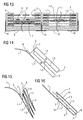
- FIG. 10 shows a cleaning device on a flat roof surface 9 with also 4 layers with lateral Spacer in longitudinal section.
- the 3 upper layers laterally completely off the spacers 2 framed, with the layers tapered downwards converge. Through the side facing becomes the water in the rooms formed by the layers especially well restrained.
- the lower layer 1.1 is essential here longer formed from the remaining layers and so can clamped, for example, with a tile arranged above or become hooked.
- the illustration shown can also only be used as one-sided part of a symmetrical ridge element considered, in which the lower layer 1.1 the Roof ridge covers or even forms itself.
- this type of execution when mounted in lower areas of a roof is particularly well suited as a snow brake or at least this function additionally takes over. Also combinations from parallel and conically arranged layers are possible.
- FIG. 11 shows a 3D representation for a better view with wire model of the roof cleaning device from Figure 8, while the figure 12 is a 3D representation of Roof cleaning device of Figure 10 shows.
- FIG 13 is a cross section through a roof cleaning device similar to the figures 8 or 10, but with shown differently executed layers.
- Left is the lower layer without openings with an overlying one Sintered insert shown.
- Above it is a fine perforated layer 1.2, above a coarser perforated layer 1.3 followed by the one with big holes or slots 6 openwork upper layer 1.4.
- the position and number of connecting elements can be varied can.
- FIG. 13 shows another arrangement the layers 1.1 to 1.4.
- the upper layer 1.4 is closed trained, underneath is a strong structured uniformly thick sintered surface 1.3, followed from a sintered layer 1.2, which is formed centrally thicker is considered marginal, again followed by a strongly perforated one lower layer 1.1.
- the cleaning device of a flat copper material to be punched, pointing out is that under punching all manufacturing processes too understand that fall under this term - see for example DIN 9870 or "Die Wegbau", 1997, ISBN 3-8085-1202-4, in particular chapter 1 "punching technique".
- FIG. 14 shows an example of such a cleaning device in longitudinal section, by multiple Abandoned and wrinkles produced 4 perforated layers. shown is a side of a ridge element that is symmetrical arranged opposite side is not shown in the picture.
- this type of design and Production also for other types of cleaning device used, for example, for similar configurations as in the previous figures.
- FIG. 1 A specific variant is shown in FIG a cleaning device 1 of 3 V-shaped folded and mated layers, of which perforated 2 layers are formed. As spacers act here the above-arranged bends, each on the support the lower layer and thus the distance and alignment determine the positions.
- Figure 16 shows a longitudinal section through a simple folded roof cleaning device 1, which is a kind of bag forms, in which an intermediate layer 1.3 with integrated spacers 2 is inserted.
- the liner is in the bottom Inserted into a groove area, here also as Spacer 2 is used. Additionally, they are located below in the folded bag forming the layers 1.1 and 1.3 small outlets 6, which store the stored liquid after appropriate reaction time and nachdrDeutschendem new Drain rainwater.
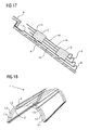
- FIG. 17 again shows a variant of a cleaning device on a flat roof surface with 4 layers 1.1 to 1.4 with lateral spacers 2 in longitudinal section.
- layers 1.2 to 1.4 are on each side two spacers attached, which themselves into the lower Location 1.1 are clipped.
- the lower layer 1.1 is through the ends of the holder 2 at a distance to the underlying Surface is held and is arranged with the above Tiles against slipping hooked.
- a roof ridge element used as a roof cleaning device is designed and basically of its construction the cleaning device of FIG. 16 corresponds to FIG of Figure 18 shown in 3D representation as a wire model. These curved surfaces are also very easy and cost-effectively by punching method.
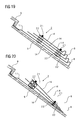
- Figures 19 and 21 show further exemplary embodiments the cleaning device according to the invention in particular to the variety of forms and execution of the spacers 2.
- Figure 19 shows a cleaning device similar to Figure 17, but here are the individual layers 1.x not the same length, but shorten from the bottom Position 1.1 up to the upper layer 1.4. This will achieve that in moderately to slightly occurring rain all Interspaces 14 between the layers even without openings in the surface of the layers are filled with moisture. This applies to both stable layers of sheet metal as well as layers made of flexible foil.
- Spacer 2 shown. These consist of one Combination of spacers 2.2 and one through the Spacer rings performed connecting element 2.1. For example can as spacers simple washers, Rings or wedges made of various materials like plastic, rubber or metal are taken.
- FIG. 20 shows how by different height spacers a conical Course of the layers 1.x can be reached.
- FIG correspondingly wide contact surface of the spacer elements 2.2 also sufficient to install only one spacer 2 per side, to achieve a sufficient fixation of the layers.
- the same is also in the figure 22 for a non-parallel course of the layers 1.x shown. additionally is here at the lower duck of the lower layer 1.1 still one - shown in chiselled - flanging or bevel 15 shown into which the upper layers can be inserted, to achieve additional fixation.
- the last figure 23 finally shows a further inventive Device in which by means of a punching process from the surface of the layers 1.2-1.4 integrated spacer elements 2.2 are withdrawn and not anymore must be used individually.
- a centering element 2.3 is inserted, at the same time as a kind of washer serves for the connection element 2.1.
- This can for example be made of plastic, or too designed as a metal sleeve with washer lying on top be.
- a Cleaning device disclosed which is suitable due to the most favorable moisture storage and at the same time strong enlargement of the reaction surface under different climatic conditions cleaning surfaces exposed to the weather cause.
- cleaning devices are not exclusive can serve for cleaning roofs, but in addition also clean other weathered surfaces, For example, this may be solar systems, Glass fronts, glass roofs or building facades act.
Landscapes
- Engineering & Computer Science (AREA)
- Life Sciences & Earth Sciences (AREA)
- Biotechnology (AREA)
- Architecture (AREA)
- Civil Engineering (AREA)
- Structural Engineering (AREA)
- Roof Covering Using Slabs Or Stiff Sheets (AREA)
- Cleaning In General (AREA)
- Cleaning By Liquid Or Steam (AREA)
- Cleaning And De-Greasing Of Metallic Materials By Chemical Methods (AREA)
- Forms Removed On Construction Sites Or Auxiliary Members Thereof (AREA)
- Mechanical Treatment Of Semiconductor (AREA)
- Photoreceptors In Electrophotography (AREA)
- Cleaning Of Streets, Tracks, Or Beaches (AREA)
Claims (38)
- Dispositif de nettoyage (1) à appliquer sur une surface exposée aux intempéries, notamment un toit, la surface d'un toit, la surface d'un équipement à énergie solaire ou une façade, le dispositif de nettoyage présentant des surfaces réactives qui sont disposées par couches et présentant une surface métallique, de préférence contenant du cuivre, lesquelles produisent, en combinaison avec l'eau, des composés nettoyants, de préférence fongicides et/ou bactéricides qui, dissous dans l'eau, peuvent au moins partiellement imprégner le toit, caractérisé en ce que sont prévues au moins une couche extérieure (1.n), une couche inférieure (1.1) et au moins une couche intermédiaire (1.2 - 1.n-1), au moins deux couches étant séparées l'une de l'autre au moins sur une zone partielle de leur surface par des entretoises (2) de telle sorte que se forment entre les couches des espaces (14) dans lesquels l'humidité naturelle, notamment l'eau de pluie, peut pénétrer et de nouveau en être expulsée.
- Dispositif de nettoyage selon la revendication 1 qui précède, caractérisé en ce que la couche extérieure (1.n) présente une pluralité de traversées (6).
- Dispositif de nettoyage selon l'une des revendications 1 à 2 qui précèdent, caractérisé en ce que l'au moins une couche intermédiaire métallique (1.2 - 1.n-1) présente une pluralité de traversées (6).
- Dispositif de nettoyage selon l'une des revendications 1 à 3 qui précèdent, caractérisé en ce que l'au moins une couche (1.1) disposée du côté du toit présente une pluralité de traversées (6).
- Dispositif de nettoyage selon l'une des revendications 1 à 4 qui précèdent, caractérisé en ce que les au moins deux couches (1.x) sont disposées parallèlement l'une à l'autre à l'aide des entretoises (2) .
- Dispositif de nettoyage selon l'une des revendications 1 à 5 qui précèdent, caractérisé en ce que les au moins deux couches (1.x) sont disposées de manière conique l'une par rapport à l'autre à l'aide des entretoises (2).
- Dispositif de nettoyage selon l'une des revendications 1 à 6 qui précèdent, caractérisé en ce que les entretoises (2) entre deux couches ne touchent une couche (1.x) que de manière ponctuelle ou linéaire.
- Dispositif de nettoyage selon l'une des revendications 1 à 7 qui précèdent, caractérisé en ce que les entretoises (2) constituent une partie d'une couche façonnée (1.x) et sont de préférence fabriquées par un outil d'estampage.
- Dispositif de nettoyage selon l'une des revendications 1 à 8 qui précèdent, caractérisé en ce qu'au moins une couche disposée au-dessous (1.x) présente pour au moins une couche disposée au-dessus (1.x+1) un bossage (8) et/ou une charnière qui soutient de manière linéaire du côté de l'extrémité, de préférence au moins par sections, l'au moins une couche disposée au-dessus (1.x+1).
- Dispositif de nettoyage selon l'une des revendications 1 à 9 qui précèdent, caractérisé en ce qu'il est réalisé sous la forme d'une faítière.
- Dispositif de nettoyage selon l'une des revendications 1 à 9 qui précèdent, caractérisé en ce que son contour et/ou sa surface est adapté(e) aux liteaux et tuiles connus.
- Dispositif de nettoyage selon l'une des revendications 1 à 11 qui précèdent, caractérisé en ce que les entretoises (2), au moins dans la zone qui se trouve vers le haut, produisent un écart minimal, de préférence supérieur à 1 mm, de préférence compris entre 2 et 3 mm, pour lequel un effet capillaire pour l'eau qui pénètre est négligeable.
- Dispositif de nettoyage selon l'une des revendications 1 à 12 qui précèdent, caractérisé en ce que sont prévues au moins deux couches intermédiaires (1.2, 1.n-1), de préférence exactement deux couches intermédiaires (1.2, 1.3).
- Dispositif de nettoyage selon l'une des revendications 1 à 13 qui précèdent, caractérisé en ce que toutes les couches (1.x) sont séparées les unes des autres par des entretoises (2).
- Dispositif de nettoyage selon l'une des revendications 1 à 14 qui précèdent, caractérisé en ce que les entretoises (2) présentent des hauteurs différentes.
- Dispositif de nettoyage selon l'une des revendications 1 à 15 qui précèdent, caractérisé en ce qu'au moins entre deux couches la fente d'entrée de l'eau (6) est plus grande que la fente de sortie de l'eau (12).
- Dispositif de nettoyage selon l'une des revendications 1 à 16 qui précèdent, caractérisé en ce que dans les espaces (14) formés par les couches, est disposé un matériau à base de cuivre à surface fortement grossie, de préférence un granulat et/ou des flocons et/ou un treillis et/ou de la laine et/ou des fibres de cuivre et/ou des pièces frittées.
- Dispositif de nettoyage selon l'une des revendications 1 à 17 qui précèdent, caractérisé en ce que les couches sont décalées latéralement et/ou en hauteur les unes par rapport aux autres.
- Dispositif de nettoyage selon l'une des revendications 1 à 18 qui précèdent, caractérisé en ce que les couches (1.x) présentent des bandes de solin et/ou des biseaux à deux extrémités opposées.
- Dispositif de nettoyage selon l'une des revendications 1 à 19 qui précèdent, caractérisé en ce qu'au moins la couche extérieure et la couche inférieure (1.1, 1.n), de préférence toutes les couches (1.x) sont reliées entre elles par des vis et/ou des clous (5) et/ou des rivets et/ou des liaisons soudées et/ou des liaisons collées.
- Dispositif de nettoyage selon l'une des revendications 1 à 20 qui précèdent, caractérisé en ce que les couches (1.x) sont adaptées à la forme de la surface tridimensionnelle des sections de toit et/ou des tuiles et/ou des équipements solaires.
- Dispositif de nettoyage selon l'une des revendications 1 à 21 qui précèdent, caractérisé en ce qu'au moins la couche inférieure (1.1) présente des éléments de fixation (5) et/ou des attaches de fixation avec lesquels elle peut être fixée à la surface à nettoyer.
- Dispositif de nettoyage selon la revendication 22 qui précède, caractérisé en ce que les attaches de fixation et/ou les éléments de fixation se composent au moins partiellement de matière plastique et sont enclipsés de préférence au moins dans une couche, de préférence la couche inférieure.
- Dispositif de nettoyage selon l'une des revendications 1 à 23 qui précèdent, caractérisé en ce que les entretoises (2) présentent des ouvertures (6) vers le dessous de la couche (1.x) qui est orientée dans le sens inverse à l'écoulement de l'eau.
- Dispositif de nettoyage selon l'une des revendications 1 à 24 qui précèdent, caractérisé en ce que les entretoises (2) et/ou les ouvertures (6) sont disposées dans les couches en étant décalées d'une couche (1.x) à l'autre (1.x+1).
- Dispositif de nettoyage selon l'une des revendications 1 à 25 qui précèdent, caractérisé en ce que les entretoises (2) sont au moins partiellement fabriquées en matière plastique.
- Dispositif de nettoyage selon l'une des revendications 1 à 23 qui précèdent, caractérisé en ce que les entretoises (2) sont configurées à la manière d'un treillis et/ou d'un tissu.
- Dispositif de nettoyage selon l'une des revendications 1 à 27 qui précèdent, caractérisé en ce qu'au moins deux couches (1.x), de préférence la couche extérieure et la couche inférieure, sont fabriquées d'une seule pièce.
- Dispositif de nettoyage selon l'une des revendications 1 à 28 qui précèdent, caractérisé en ce que plus de deux couches (1.x), de préférence toutes les couches, sont fabriquées d'une seule pièce, de préférence par plusieurs biseautages et pliages.
- Dispositif de nettoyage selon l'une des revendications 1 à 29 qui précèdent, caractérisé en ce que les couches (1.x) sont au moins en partie courbées dans le sens longitudinal.
- Dispositif de nettoyage selon l'une des revendications 1 à 30 qui précèdent, caractérisé en ce que les couches (1.x) sont au moins en partie courbées dans le sens transversal.
- Dispositif de nettoyage selon l'une des revendications 1 à 31 qui précèdent, caractérisé en ce que les entretoises (2) sont disposées latéralement aux couches.
- Dispositif de nettoyage selon la revendication 32 qui précède, caractérisé en ce que les entretoises (2) s'étendent sur toute la longueur des couches (1.x) et ferment latéralement, au moins en grande partie, les espaces (14) formés entre les couches.
- Dispositif de nettoyage selon l'une des revendications 32 à 33 qui précèdent, caractérisé en ce que sont prévues des pattes (10) qui fixent les entretoises (2) au toit et/ou à une couverture de toit et/ou à la couche inférieure (1.1).
- Dispositif de nettoyage selon l'une des revendications 32 à 34 qui précèdent, caractérisé en ce qu'au moins un élément de liaison (11), de préférence un élément de liaison élastique, est prévu entre au moins deux entretoises (2).
- Dispositif de nettoyage selon l'une des revendications 1 à 35 qui précèdent, caractérisé en ce que sont prévus des rebords latéraux pour former des espaces dans lesquels l'eau est retenue.
- Dispositif de nettoyage selon l'une des revendications 1 à 36 qui précèdent, caractérisé en ce qu'au moins une couche (1.x), de préférence toutes les couches, se composent d'une feuille.
- Dispositif de nettoyage selon l'une des revendications 1 à 37 qui précèdent, caractérisé en ce qu'au moins une couche (1.x), de préférence toutes les couches, ont leur surface incrustée de bossages et de creux par estampage, notamment par laminage au rouleau.
Applications Claiming Priority (2)
| Application Number | Priority Date | Filing Date | Title |
|---|---|---|---|
| DE20220561U | 2002-08-11 | ||
| DE20220561U DE20220561U1 (de) | 2002-08-11 | 2002-08-11 | Reinigungsvorrichtung zum Aufbringen auf eine dem Wetter ausgesetzte Oberfläche |
Publications (2)
| Publication Number | Publication Date |
|---|---|
| EP1389659A1 EP1389659A1 (fr) | 2004-02-18 |
| EP1389659B1 true EP1389659B1 (fr) | 2005-03-16 |
Family
ID=30469930
Family Applications (1)
| Application Number | Title | Priority Date | Filing Date |
|---|---|---|---|
| EP03018007A Expired - Lifetime EP1389659B1 (fr) | 2002-08-11 | 2003-08-07 | Dispositif de nettoyage pour surfaces exposées aux intempéries |
Country Status (6)
| Country | Link |
|---|---|
| EP (1) | EP1389659B1 (fr) |
| AT (1) | ATE291136T1 (fr) |
| DE (2) | DE20220561U1 (fr) |
| DK (1) | DK1389659T3 (fr) |
| ES (1) | ES2240897T3 (fr) |
| SI (1) | SI1389659T1 (fr) |
Families Citing this family (4)
| Publication number | Priority date | Publication date | Assignee | Title |
|---|---|---|---|---|
| DE10352839B3 (de) * | 2003-11-10 | 2005-03-24 | Hugo Weber | Reinigungsvorrichtung zum Aufbringen auf eine dem Wetter ausgesetzte Oberfläche |
| WO2005071181A1 (fr) | 2004-01-26 | 2005-08-04 | Hugo Weber | Dispositif de nettoyage forme d'une tole de cuivre pour des surfaces exposees aux intemperies |
| EP1887159B1 (fr) * | 2006-08-07 | 2009-06-03 | Hugo Weber | Dispositif de nettoyage qui est indépendant du temps |
| CA2791532C (fr) * | 2011-12-19 | 2015-04-14 | David Spencer | Insertions de bardeau et methode d'elimination et de prevention de la croissance d'algues, de mousses ou de lichens sur un toit |
Family Cites Families (4)
| Publication number | Priority date | Publication date | Assignee | Title |
|---|---|---|---|---|
| DE29804136U1 (de) * | 1998-03-09 | 1999-05-12 | Röhner, Horst, 91599 Dentlein | Dachschutz-Abdeckung teilweise oder Auflage als Grundkörper, integrierter Blitzableiter mehrschichtiger, durchlässigen Oberfläche ausgeprägten Flächen gegen Dachbewuchs/Reinigung |
| DE10058855C1 (de) | 2000-11-27 | 2002-04-04 | Hoesch Paul Michael | Firstelement aus Kupfer |
| DE20104404U1 (de) * | 2001-03-14 | 2001-06-13 | Hepp, Edgar, 97901 Altenbuch | Firstabdeckung |
| DE20104999U1 (de) * | 2001-03-16 | 2001-05-23 | Vaclavik, Josef, 90763 Fürth | Vorrichtung zum Beseitigen von pflanzlichem Bewuchs auf geneigten Dächern |
-
2002
- 2002-08-11 DE DE20220561U patent/DE20220561U1/de not_active Expired - Lifetime
-
2003
- 2003-08-07 EP EP03018007A patent/EP1389659B1/fr not_active Expired - Lifetime
- 2003-08-07 SI SI200330037T patent/SI1389659T1/xx unknown
- 2003-08-07 DK DK03018007T patent/DK1389659T3/da active
- 2003-08-07 AT AT03018007T patent/ATE291136T1/de not_active IP Right Cessation
- 2003-08-07 ES ES03018007T patent/ES2240897T3/es not_active Expired - Lifetime
- 2003-08-07 DE DE50300364T patent/DE50300364D1/de not_active Expired - Lifetime
Also Published As
| Publication number | Publication date |
|---|---|
| EP1389659A1 (fr) | 2004-02-18 |
| DE50300364D1 (de) | 2005-04-21 |
| DE20220561U1 (de) | 2003-12-24 |
| SI1389659T1 (en) | 2005-10-31 |
| ATE291136T1 (de) | 2005-04-15 |
| ES2240897T3 (es) | 2005-10-16 |
| DK1389659T3 (da) | 2005-07-25 |
Similar Documents
| Publication | Publication Date | Title |
|---|---|---|
| DE60220760T2 (de) | Solarpaneelanordnung | |
| WO1997037387A1 (fr) | Element de sous-couverture pour un element de construction plat en forme de panneau | |
| DE102005028830A1 (de) | Dacheindeckung und Verfahren hierfür | |
| EP0724048B1 (fr) | Bande d'étanchéité enroulable pour faíte et/ou arête de couverture | |
| EP1724508B1 (fr) | Tuyau | |
| AT390104B (de) | Traufausbildung | |
| EP1389659B1 (fr) | Dispositif de nettoyage pour surfaces exposées aux intempéries | |
| WO2004018793A1 (fr) | Systeme de nettoyage destine a etre installe sur une surface exposee aux intemperies | |
| EP1228280B1 (fr) | Couverture du faítage | |
| EP1306627A2 (fr) | Dispositif pour l'utilisation de l'énergie solaire | |
| DE20221082U1 (de) | Reinigungsvorrichtung zum Aufbringen auf eine dem Wetter ausgesetzte Oberfläche | |
| DE29604146U1 (de) | Dichtungsstreifen für eine First- und/oder Gratabdeckung | |
| EP3936680B1 (fr) | Revêtement de façade ou de toiture comportant des éléments de revêtement | |
| DE10352839B3 (de) | Reinigungsvorrichtung zum Aufbringen auf eine dem Wetter ausgesetzte Oberfläche | |
| DE19734346A1 (de) | Dachdurchdringungs-Einfassung | |
| DE10105126C1 (de) | Abdeckrost | |
| DE29722219U1 (de) | Lamelle für ein Sonnen- und/oder Wärmeschutzsystem | |
| EP4093915B1 (fr) | Module fonctionnel recouvert de végétation, bâtiment et barrière anti-bruit | |
| EP0182819A1 (fr) | Faux plafond pour locaux de travail | |
| DE2642999B1 (de) | Selbstspannende Wandbekleidungsplatte | |
| EP3680413B1 (fr) | Assemblage avec un élément de couverture de toit extrudé | |
| DE29623686U1 (de) | Rollbarer Dichtungsstreifen für eine First- und/oder Gratabdeckung | |
| EP1074673B1 (fr) | Elément d'étanchéité de rive flexible | |
| AT407174B (de) | Randstreifen an dachtraufen | |
| EP1191160A1 (fr) | Dispositif d'écoulement |
Legal Events
| Date | Code | Title | Description |
|---|---|---|---|
| PUAI | Public reference made under article 153(3) epc to a published international application that has entered the european phase |
Free format text: ORIGINAL CODE: 0009012 |
|
| AK | Designated contracting states |
Kind code of ref document: A1 Designated state(s): AT BE BG CH CY CZ DE DK EE ES FI FR GB GR HU IE IT LI LU MC NL PT RO SE SI SK TR |
|
| AX | Request for extension of the european patent |
Extension state: AL LT LV MK |
|
| 17P | Request for examination filed |
Effective date: 20040424 |
|
| AKX | Designation fees paid |
Designated state(s): AT BE BG CH CY CZ DE DK EE ES FI FR GB GR HU IE IT LI LU MC NL PT RO SE SI SK TR |
|
| GRAP | Despatch of communication of intention to grant a patent |
Free format text: ORIGINAL CODE: EPIDOSNIGR1 |
|
| GRAA | (expected) grant |
Free format text: ORIGINAL CODE: 0009210 |
|
| GRAS | Grant fee paid |
Free format text: ORIGINAL CODE: EPIDOSNIGR3 |
|
| GRAL | Information related to payment of fee for publishing/printing deleted |
Free format text: ORIGINAL CODE: EPIDOSDIGR3 |
|
| GRAS | Grant fee paid |
Free format text: ORIGINAL CODE: EPIDOSNIGR3 |
|
| AK | Designated contracting states |
Kind code of ref document: B1 Designated state(s): AT BE BG CH CY CZ DE DK EE ES FI FR GB GR HU IE IT LI LU MC NL PT RO SE SI SK TR |
|
| PG25 | Lapsed in a contracting state [announced via postgrant information from national office to epo] |
Ref country code: RO Free format text: LAPSE BECAUSE OF FAILURE TO SUBMIT A TRANSLATION OF THE DESCRIPTION OR TO PAY THE FEE WITHIN THE PRESCRIBED TIME-LIMIT Effective date: 20050316 Ref country code: EE Free format text: LAPSE BECAUSE OF FAILURE TO SUBMIT A TRANSLATION OF THE DESCRIPTION OR TO PAY THE FEE WITHIN THE PRESCRIBED TIME-LIMIT Effective date: 20050316 Ref country code: SK Free format text: LAPSE BECAUSE OF FAILURE TO SUBMIT A TRANSLATION OF THE DESCRIPTION OR TO PAY THE FEE WITHIN THE PRESCRIBED TIME-LIMIT Effective date: 20050316 Ref country code: TR Free format text: LAPSE BECAUSE OF FAILURE TO SUBMIT A TRANSLATION OF THE DESCRIPTION OR TO PAY THE FEE WITHIN THE PRESCRIBED TIME-LIMIT Effective date: 20050316 |
|
| REG | Reference to a national code |
Ref country code: GB Ref legal event code: FG4D Free format text: NOT ENGLISH |
|
| REG | Reference to a national code |
Ref country code: CH Ref legal event code: EP |
|
| REG | Reference to a national code |
Ref country code: IE Ref legal event code: FG4D Free format text: GERMAN |
|
| REF | Corresponds to: |
Ref document number: 50300364 Country of ref document: DE Date of ref document: 20050421 Kind code of ref document: P |
|
| PG25 | Lapsed in a contracting state [announced via postgrant information from national office to epo] |
Ref country code: BG Free format text: LAPSE BECAUSE OF FAILURE TO SUBMIT A TRANSLATION OF THE DESCRIPTION OR TO PAY THE FEE WITHIN THE PRESCRIBED TIME-LIMIT Effective date: 20050616 Ref country code: GR Free format text: LAPSE BECAUSE OF FAILURE TO SUBMIT A TRANSLATION OF THE DESCRIPTION OR TO PAY THE FEE WITHIN THE PRESCRIBED TIME-LIMIT Effective date: 20050616 |
|
| PG25 | Lapsed in a contracting state [announced via postgrant information from national office to epo] |
Ref country code: HU Free format text: LAPSE BECAUSE OF FAILURE TO SUBMIT A TRANSLATION OF THE DESCRIPTION OR TO PAY THE FEE WITHIN THE PRESCRIBED TIME-LIMIT Effective date: 20050617 |
|
| REG | Reference to a national code |
Ref country code: SE Ref legal event code: TRGR |
|
| GBT | Gb: translation of ep patent filed (gb section 77(6)(a)/1977) |
Effective date: 20050607 |
|
| REG | Reference to a national code |
Ref country code: DK Ref legal event code: T3 |
|
| PG25 | Lapsed in a contracting state [announced via postgrant information from national office to epo] |
Ref country code: CY Free format text: LAPSE BECAUSE OF FAILURE TO SUBMIT A TRANSLATION OF THE DESCRIPTION OR TO PAY THE FEE WITHIN THE PRESCRIBED TIME-LIMIT Effective date: 20050807 |
|
| PG25 | Lapsed in a contracting state [announced via postgrant information from national office to epo] |
Ref country code: MC Free format text: LAPSE BECAUSE OF NON-PAYMENT OF DUE FEES Effective date: 20050831 |
|
| PG25 | Lapsed in a contracting state [announced via postgrant information from national office to epo] |
Ref country code: PT Free format text: LAPSE BECAUSE OF FAILURE TO SUBMIT A TRANSLATION OF THE DESCRIPTION OR TO PAY THE FEE WITHIN THE PRESCRIBED TIME-LIMIT Effective date: 20050907 |
|
| REG | Reference to a national code |
Ref country code: ES Ref legal event code: FG2A Ref document number: 2240897 Country of ref document: ES Kind code of ref document: T3 |
|
| PLBE | No opposition filed within time limit |
Free format text: ORIGINAL CODE: 0009261 |
|
| STAA | Information on the status of an ep patent application or granted ep patent |
Free format text: STATUS: NO OPPOSITION FILED WITHIN TIME LIMIT |
|
| ET | Fr: translation filed | ||
| 26N | No opposition filed |
Effective date: 20051219 |
|
| PGFP | Annual fee paid to national office [announced via postgrant information from national office to epo] |
Ref country code: DK Payment date: 20080822 Year of fee payment: 6 Ref country code: NL Payment date: 20080820 Year of fee payment: 6 |
|
| PGFP | Annual fee paid to national office [announced via postgrant information from national office to epo] |
Ref country code: AT Payment date: 20080821 Year of fee payment: 6 Ref country code: FI Payment date: 20080825 Year of fee payment: 6 Ref country code: IE Payment date: 20080819 Year of fee payment: 6 |
|
| PGFP | Annual fee paid to national office [announced via postgrant information from national office to epo] |
Ref country code: LU Payment date: 20090824 Year of fee payment: 7 Ref country code: SE Payment date: 20090821 Year of fee payment: 7 |
|
| PGFP | Annual fee paid to national office [announced via postgrant information from national office to epo] |
Ref country code: BE Payment date: 20090821 Year of fee payment: 7 |
|
| REG | Reference to a national code |
Ref country code: NL Ref legal event code: V1 Effective date: 20100301 |
|
| REG | Reference to a national code |
Ref country code: DK Ref legal event code: EBP |
|
| PG25 | Lapsed in a contracting state [announced via postgrant information from national office to epo] |
Ref country code: FI Free format text: LAPSE BECAUSE OF NON-PAYMENT OF DUE FEES Effective date: 20090807 |
|
| PGFP | Annual fee paid to national office [announced via postgrant information from national office to epo] |
Ref country code: IT Payment date: 20090824 Year of fee payment: 7 |
|
| REG | Reference to a national code |
Ref country code: IE Ref legal event code: MM4A |
|
| PG25 | Lapsed in a contracting state [announced via postgrant information from national office to epo] |
Ref country code: AT Free format text: LAPSE BECAUSE OF NON-PAYMENT OF DUE FEES Effective date: 20090807 |
|
| PG25 | Lapsed in a contracting state [announced via postgrant information from national office to epo] |
Ref country code: IE Free format text: LAPSE BECAUSE OF NON-PAYMENT OF DUE FEES Effective date: 20090807 Ref country code: DK Free format text: LAPSE BECAUSE OF NON-PAYMENT OF DUE FEES Effective date: 20090831 Ref country code: NL Free format text: LAPSE BECAUSE OF NON-PAYMENT OF DUE FEES Effective date: 20100301 |
|
| PGFP | Annual fee paid to national office [announced via postgrant information from national office to epo] |
Ref country code: CH Payment date: 20100825 Year of fee payment: 8 Ref country code: ES Payment date: 20100830 Year of fee payment: 8 |
|
| PGFP | Annual fee paid to national office [announced via postgrant information from national office to epo] |
Ref country code: CZ Payment date: 20100727 Year of fee payment: 8 Ref country code: FR Payment date: 20100901 Year of fee payment: 8 Ref country code: SI Payment date: 20100728 Year of fee payment: 8 |
|
| PGFP | Annual fee paid to national office [announced via postgrant information from national office to epo] |
Ref country code: GB Payment date: 20100823 Year of fee payment: 8 |
|
| BERE | Be: lapsed |
Owner name: *WEBER HUGO Effective date: 20100831 |
|
| PGFP | Annual fee paid to national office [announced via postgrant information from national office to epo] |
Ref country code: DE Payment date: 20100922 Year of fee payment: 8 |
|
| EUG | Se: european patent has lapsed | ||
| PG25 | Lapsed in a contracting state [announced via postgrant information from national office to epo] |
Ref country code: IT Free format text: LAPSE BECAUSE OF NON-PAYMENT OF DUE FEES Effective date: 20100807 |
|
| PG25 | Lapsed in a contracting state [announced via postgrant information from national office to epo] |
Ref country code: BE Free format text: LAPSE BECAUSE OF NON-PAYMENT OF DUE FEES Effective date: 20100831 |
|
| REG | Reference to a national code |
Ref country code: CH Ref legal event code: PL |
|
| GBPC | Gb: european patent ceased through non-payment of renewal fee |
Effective date: 20110807 |
|
| PG25 | Lapsed in a contracting state [announced via postgrant information from national office to epo] |
Ref country code: CH Free format text: LAPSE BECAUSE OF NON-PAYMENT OF DUE FEES Effective date: 20110831 Ref country code: CZ Free format text: LAPSE BECAUSE OF NON-PAYMENT OF DUE FEES Effective date: 20110807 Ref country code: LI Free format text: LAPSE BECAUSE OF NON-PAYMENT OF DUE FEES Effective date: 20110831 |
|
| REG | Reference to a national code |
Ref country code: SI Ref legal event code: KO00 Effective date: 20120309 |
|
| REG | Reference to a national code |
Ref country code: FR Ref legal event code: ST Effective date: 20120430 |
|
| PG25 | Lapsed in a contracting state [announced via postgrant information from national office to epo] |
Ref country code: SI Free format text: LAPSE BECAUSE OF NON-PAYMENT OF DUE FEES Effective date: 20110808 |
|
| REG | Reference to a national code |
Ref country code: DE Ref legal event code: R119 Ref document number: 50300364 Country of ref document: DE Effective date: 20120301 |
|
| PG25 | Lapsed in a contracting state [announced via postgrant information from national office to epo] |
Ref country code: FR Free format text: LAPSE BECAUSE OF NON-PAYMENT OF DUE FEES Effective date: 20110831 Ref country code: GB Free format text: LAPSE BECAUSE OF NON-PAYMENT OF DUE FEES Effective date: 20110807 |
|
| PG25 | Lapsed in a contracting state [announced via postgrant information from national office to epo] |
Ref country code: SE Free format text: LAPSE BECAUSE OF NON-PAYMENT OF DUE FEES Effective date: 20100808 Ref country code: LU Free format text: LAPSE BECAUSE OF NON-PAYMENT OF DUE FEES Effective date: 20100807 |
|
| REG | Reference to a national code |
Ref country code: ES Ref legal event code: FD2A Effective date: 20130530 |
|
| PG25 | Lapsed in a contracting state [announced via postgrant information from national office to epo] |
Ref country code: DE Free format text: LAPSE BECAUSE OF NON-PAYMENT OF DUE FEES Effective date: 20120301 |
|
| PG25 | Lapsed in a contracting state [announced via postgrant information from national office to epo] |
Ref country code: ES Free format text: LAPSE BECAUSE OF NON-PAYMENT OF DUE FEES Effective date: 20110808 |