EP1389659B1 - Cleaning device for surfaces exposed to the inclemency of weather - Google Patents
Cleaning device for surfaces exposed to the inclemency of weather Download PDFInfo
- Publication number
- EP1389659B1 EP1389659B1 EP03018007A EP03018007A EP1389659B1 EP 1389659 B1 EP1389659 B1 EP 1389659B1 EP 03018007 A EP03018007 A EP 03018007A EP 03018007 A EP03018007 A EP 03018007A EP 1389659 B1 EP1389659 B1 EP 1389659B1
- Authority
- EP
- European Patent Office
- Prior art keywords
- cleaning device
- layers
- preceding patent
- spacers
- layer
- Prior art date
- Legal status (The legal status is an assumption and is not a legal conclusion. Google has not performed a legal analysis and makes no representation as to the accuracy of the status listed.)
- Expired - Lifetime
Links
- 238000004140 cleaning Methods 0.000 title claims abstract description 127
- 125000006850 spacer group Chemical group 0.000 claims abstract description 65
- XLYOFNOQVPJJNP-UHFFFAOYSA-N water Substances O XLYOFNOQVPJJNP-UHFFFAOYSA-N 0.000 claims abstract description 34
- RYGMFSIKBFXOCR-UHFFFAOYSA-N Copper Chemical compound [Cu] RYGMFSIKBFXOCR-UHFFFAOYSA-N 0.000 claims abstract description 21
- 239000010949 copper Substances 0.000 claims abstract description 19
- 229910052802 copper Inorganic materials 0.000 claims abstract description 19
- 230000000844 anti-bacterial effect Effects 0.000 claims abstract description 4
- 150000001875 compounds Chemical class 0.000 claims abstract description 4
- 230000000855 fungicidal effect Effects 0.000 claims abstract description 4
- 230000000694 effects Effects 0.000 claims description 9
- 238000004080 punching Methods 0.000 claims description 9
- 239000004033 plastic Substances 0.000 claims description 8
- 239000000463 material Substances 0.000 claims description 7
- 239000011324 bead Substances 0.000 claims description 6
- 230000009471 action Effects 0.000 claims description 4
- 239000004744 fabric Substances 0.000 claims description 3
- 239000000853 adhesive Substances 0.000 claims description 2
- 230000001070 adhesive effect Effects 0.000 claims description 2
- 239000011888 foil Substances 0.000 claims description 2
- 239000008187 granular material Substances 0.000 claims description 2
- 238000005096 rolling process Methods 0.000 claims description 2
- 238000007688 edging Methods 0.000 claims 1
- 239000008188 pellet Substances 0.000 claims 1
- 230000000149 penetrating effect Effects 0.000 claims 1
- 230000000717 retained effect Effects 0.000 claims 1
- 238000006243 chemical reaction Methods 0.000 abstract description 10
- 239000010410 layer Substances 0.000 description 152
- 238000013461 design Methods 0.000 description 7
- 239000002184 metal Substances 0.000 description 6
- 229910052751 metal Inorganic materials 0.000 description 6
- 238000003860 storage Methods 0.000 description 6
- 238000004519 manufacturing process Methods 0.000 description 5
- 238000000034 method Methods 0.000 description 5
- 239000000126 substance Substances 0.000 description 5
- 239000011449 brick Substances 0.000 description 3
- 238000001704 evaporation Methods 0.000 description 3
- 230000008020 evaporation Effects 0.000 description 3
- 239000011521 glass Substances 0.000 description 3
- 239000007788 liquid Substances 0.000 description 3
- 238000012549 training Methods 0.000 description 3
- 230000008901 benefit Effects 0.000 description 2
- 230000015572 biosynthetic process Effects 0.000 description 2
- 239000007795 chemical reaction product Substances 0.000 description 2
- 239000011889 copper foil Substances 0.000 description 2
- 238000002474 experimental method Methods 0.000 description 2
- 230000002349 favourable effect Effects 0.000 description 2
- 230000006872 improvement Effects 0.000 description 2
- 230000008569 process Effects 0.000 description 2
- 230000005855 radiation Effects 0.000 description 2
- 239000002356 single layer Substances 0.000 description 2
- 238000012546 transfer Methods 0.000 description 2
- 241000272525 Anas platyrhynchos Species 0.000 description 1
- 238000005452 bending Methods 0.000 description 1
- 230000009286 beneficial effect Effects 0.000 description 1
- 239000003795 chemical substances by application Substances 0.000 description 1
- 238000009833 condensation Methods 0.000 description 1
- 230000005494 condensation Effects 0.000 description 1
- 238000010276 construction Methods 0.000 description 1
- 239000000428 dust Substances 0.000 description 1
- 239000000835 fiber Substances 0.000 description 1
- 238000010304 firing Methods 0.000 description 1
- 239000012530 fluid Substances 0.000 description 1
- 238000011010 flushing procedure Methods 0.000 description 1
- 230000004907 flux Effects 0.000 description 1
- 230000001976 improved effect Effects 0.000 description 1
- 238000002955 isolation Methods 0.000 description 1
- 238000005304 joining Methods 0.000 description 1
- 239000008239 natural water Substances 0.000 description 1
- 230000035699 permeability Effects 0.000 description 1
- 230000035484 reaction time Effects 0.000 description 1
- 239000005060 rubber Substances 0.000 description 1
- 238000007493 shaping process Methods 0.000 description 1
- 239000010454 slate Substances 0.000 description 1
- 238000003892 spreading Methods 0.000 description 1
- 230000007480 spreading Effects 0.000 description 1
- 230000037303 wrinkles Effects 0.000 description 1
Images


Classifications
-
- E—FIXED CONSTRUCTIONS
- E04—BUILDING
- E04D—ROOF COVERINGS; SKY-LIGHTS; GUTTERS; ROOF-WORKING TOOLS
- E04D13/00—Special arrangements or devices in connection with roof coverings; Protection against birds; Roof drainage ; Sky-lights
- E04D13/002—Provisions for preventing vegetational growth, e.g. fungi, algae or moss
Definitions
- the invention relates to a cleaning device for applying on a surface exposed to the weather, in particular a roof, a roof surface, a solar system surface or a facade, wherein the device has a Has a variety of reaction surfaces arranged in layers are and a metallic, preferably copper-containing, Have surface, which in conjunction with Water-cleaning, preferably fungicidal and / or bactericidal, producing compounds that dissolved in water at least partially wet the roof.
- the utility model DE 201 04 999 U1 pointed out.
- This utility model also discloses a metallic roof ridge element, which preferably is made of copper sheets, with over the length of the roof ridge element is a chamber which is on the bottom by a through Sheet is limited and has a grid on the outside, which achieve a surface-enlarging effect should. Due to the symmetrical design of the Firstiatas will be on both sides of the roof respectively a chamber formed according to that described there The idea of the invention also by a moisture-storing Fleece or braid can be filled. practical Experiments with such a design of a ridge hood have shown that in the thus formed chamber there is no sufficient storage volume, and on top of that the storage time for natural water extremely low is because a much too early evaporation eventual Moisture occurs.
- the inventor has realized that to improve self-cleaning Effect of cleaning devices for application on a surface exposed to the weather it essential is, an optimal combination between the trapped and stored humidity and the available Asked reaction surface of the metal, in particular the Copper, which is necessary, in addition to take care wear is that also a sufficient drainage possibility the liquid stored in the meantime necessary is as soon as a new water supply, so new rain, occurs. It also seems essential that the Embodiment of the cleaning device, in particular the Chambers in which the moisture is recovered, so can be designed that the outside impinging solar radiation the inner chambers are not too much warmed to one early evaporation of moisture from the chambers too avoid.
- the inventor proposes the per se known Cleaning device for applying to a weather exposed surface, in particular a roof, a roof surface, a solar system surface or a facade, to improve, the cleaning device a variety of reaction surfaces arranged in layers are and a metallic, preferably copper-containing Having surface which cleans in conjunction with water, preferably fungicidal and / or bactericidal compounds generate that dissolved in the water at least the roof can partially wet.
- the improvement lies in that at least one upper layer, one lower layer Position and at least one intermediate layer are provided, wherein at least two layers at least over a partial area their area separated by spacers are that spaces are formed between the layers in which natural moisture, especially rainwater, tile in and can be rinsed out again.
- the occurring water is targeted to multiple levels of moisture through Spacers are formed distributed, with the in these Chambers stored moisture due to the above lying layers, for example, by sunlight relative little is heated, especially if the spacers the neighboring area only touches almost point-like, allowing the stored moisture sufficient time for Is made available with the metallic, preferably latticed surface, to respond and for the cleansing Effect necessary substances from the metallic Surface, which forms the reaction surface to dissolve.
- the inventive design that with newly occurring water one possible unimpeded flushing of these chambers takes place, so that the substances formed there freely to the outside can be washed and on the surface to be cleaned to be effective.
- the outer layer with a variety provided by breakthroughs, so that too on the surface the cleaning device incident rain relative unhindered to the bottom of each layer can penetrate. Accordingly, not only the outer one Location but also the underlying layers and possibly even the lower layer with breakthroughs be provided in order to produce a permeability there, however, the breakthroughs should be sufficiently small should be for easy shooting through of liquid too prevent. So there has to be a compromise between storage effect and obstruction of the flow of fluid be achieved.
- the individual layers to each other be arranged parallel or conical, wherein it is particularly advantageous if the distance between enlarged the individual layers upwards.
- Advantageous It is definitely when the area is out of the Sum of the inlet openings is greater than the area of Sum of the outlet openings.
- the spacers between the layers can, for example be designed so that they are as punctiform or at most in a line the areas to be kept apart It should be noted that it is the spacers are not necessarily separate Elements must act, but that the layers described can be produced by punching tools and this by appropriate shaping of the surface and optionally Cut out the openings of the spacers integrated into the surface of the individual layers can.
- the shape of the spacers is here barely set a limit, but it is advantageous if in each case the highest possible increase in the reactive Surface is satisfied by such spacers.
- Such Training allows you to overlay several layers wherein the formed beads each arranged above Protect the situation from slipping, respectively if provided between the layers of a hinge is, even a folding of the individual layers allows becomes. Since the cleaning device according to the invention the outer Weather and thus pollution by Dust or deposit of leaves of nearby trees exposed, it may be advantageous to the individual layers take apart or unfold and thus carry out a cleaning in the intermediate areas to be able to. In addition, the possibility arises through a conical opening of the individual layers also a Schneerisonêt to produce, once on a sloping Roof lying snow sets in motion, so this one by spreading layers of the cleaning device is slowed down.
- the cleaning device according to the invention can be adapted to the most diverse forms of roofs and surfaces, wherein, for example, such a cleaning device can also be designed as a roof ridge or Dachfirstabdeckung.
- the contour and / or the surface of the cleaning device can be adapted to the contours and / or surfaces of known roof tiles and roof tiles.
- the website www.braas.de or www.creaton.de is an example.
- roof cleaning device of the type mentioned can also be used on thatched roofs or roofs that are covered with slate, roofing felt, Welleternitplatten or the like, in particular, an application for solar systems or other glass or Kunststoffbedachitch is possible.
- the cleaning device only one intermediate layer, so a total of three Has layers.
- the distances of the Single layers not to keep the same, but different to create high spaces, so that as possible optimal water retention depending on the given weather conditions certain regions.
- a further improvement in the effectiveness of the cleaning device can be achieved in that of the The layers formed spaces, copper material with greatly enlarged Surface, preferably granules and / or Flakes and / or braid and / or casings and / or fibers made of copper and / or sintered pieces are arranged.
- surface enlarging agent is the reaction surface provided greatly expanded, allowing a greater effectiveness of the cleaning device is possible.
- the individual layers can be laterally and / or vertically offset be arranged to each other.
- the layers can two opposite ends up and / or bends exhibit.
- the layers can be individually loose or at least the outer and lower layers, preferably all Layers to be interconnected using known joining techniques like screws, nails, rivets, welded joints or adhesive joints are applicable.
- At least the lower layer, preferably all layers, the three-dimensional Surface shape of roof sections and / or Roof tiles and / or solar systems or other of the weather exposed surfaces are adjusted.
- Attachment of the cleaning device can at least the lower layer fasteners and / or mounting brackets exhibit.
- Such fasteners can at least partially made of plastic and in at least one of the layers, preferably the lower layer, clipped be equipped.
- this formed braid and / or tissue-like are, so that the layers are resilient to each other Keeping a distance and at the same time as possible low heat fluxes between the individual layers arise.
- these layers can be produced in one piece be here preferably by bending and Fold the corresponding spaces are generated.
- the individual layers of the cleaning device can on the one hand made of thin sheet metal, preferably copper sheet
- a film preferably a copper foil to form. If all layers of the cleaning device are formed from films, so this has the advantage that the layers are very simply the outer contour of each covered tile to adjust.
- films of thin sheets do not differ.
- the framework of the Invention also attributable to a film or layer that made is built up of several layers, not necessarily all Layers must be metallic, but only the The moisture-accessible layer must be metallic Have property to produce the cleaning effect.
- the cleaning device with at least one layer preferably equipped with all layers in the area Elevations and depressions are impressed, preferably This can be done by punching, in particular by rolling rollers.
- punching in particular by rolling rollers.
- Production of the cleaning device according to the invention particularly advantageous by at least one punching operation can be.
- a film may also be a braid or tissue can be used as a layer without the scope of To leave invention.
- a braid or tissue can be used as a layer without the scope of To leave invention.
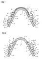
- FIG. 1 shows a cleaning device according to the invention for placing on a roof ridge tile 3.
- the cleaning device consists of four layers 1.1 - 1.4, which is the Largely embracing roof ridge tiles 3 on the top, Each layer is over both sides of the roof ridge tile extends.
- the individual layers have this punched Bulges 2 on, as a spacer between the act individual layers.
- At the bottom of each Layers are bulges 8 bent up, against which each overlying layer can support with its long side. Due to the design of the individual layers with the illustrated Spacers will be sufficient between the layers Rooms 14 generated in the rain or condensation of penetrate above openings 6 in the layers and in can collect the gaps.
- the layers are like that designed that due to the spacers only a very low thermal contact exists between them, so that too solar radiation does not cause a quick evaporation of lying in the spaces 14 water Leads, giving enough time and surface to training the chemical substances available to the Lead roof cleaning.
- FIG. 2 shows a similar cleaning device 1 a Dachfirstziegel 3, but here is only the lower Layer 1.4 designed so that it covers the entire roof ridge tile 3, while the further arranged thereon Layers 1.1 - 1.3 arranged exclusively on the side are and by fasteners 5 in the form of screws, Nails, rivets or the like prevented from slipping off become.
- the design of the individual layers corresponds essentially the representation of Figure 1, wherein also here in addition between the layers deposits, for example Copper grains, casts, sintered elements, braids or the like introduced into the spaces 14 between the layers can be.
- FIGS. 3 and 4 show two cleaning devices 1, which are arranged on flat roof tiles 9, wherein these also formed 4-ply.
- the equipment of the layers corresponds to the figures 1 or 2, again here Intermediate spaces 14 between the individual layers 1.1 - 1.4 are generated in which store moisture can.
- FIG. 4 shows a variation of the layers with regard to their Spacer in that the first one below Position 1.1 is executed, has spacers 2, which are made of good insulating plastic, so that between the lower layer 1.4 and the overlying Location 1.3 only low thermal contact exists. This will also heat through the underlying Brick as little as possible introduced into the overlying layers. Similarly, the outer layer 1.1 of the underneath lying intermediate layer 1.2 also by clipped, made of plastic spacers separated.
- the cleaning devices shown in this document represent only selected examples, with the simpler Representation also chosen simple geometric shapes were. On the one hand, this affects the surface the rest of the cleaning devices, as well as the Structure and shape of the spacers, of course different by appropriately trained punch can be executed, with very different Forms can be used. It is advantageous here usually when at least the lower layer of each form the covered surface, especially the underlying Adapts bricks, although it does may be partially advantageous when using spacers opposite the underlying surface to be cleaned is working. The design of the spacers even if formed from the individual layers themselves can be particularly beneficial if they add too much extra Lead surfaces and at the same time as possible a low heat transfer to be kept in the distance Create next location.
- FIGS. 5a to 5d show cross sections through possible ones Contours of the cleaning device. This is how the contour corresponds FIG. 5a, for example, of a Frankfurt pan, For example, the contour of FIG. 5b may be used be used on a Welleternitdach.
- Figures 5c and 5d represent simple, slightly curved or flat contours a cleaning device as they are on relative flat surfaces can be used.
- FIGS. 7a to 7c are longitudinal cross-sectional views of the firing direction through the contour of cleaning devices show how they are used for example in the ridge area.
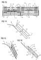
- FIG 8 is a further variant of an inventive Cleaning device are presented, the here on a roof surface with flat flat roof tiles or roof tiles 9 rests.
- the cleaning device has 4 layers of copper sheet, which are laterally mounted Spacer 2, the layers 1.1 to 1.4 substantially fix in parallel.
- the chamfers can be made of plastic, for example, leaving little heat transfer between the layers exists. Rainwater can leak up when running in penetrate the formed openings 6 and is between the Layers 1.1 to 1.4 stored in the spaces 14, where sufficient time to react with the weathered copper surface exists, hence the required chemical reactions can take place.
- the end of the cleaning device are by not completely dense clashing the layers formed outlet slots over which the enriched water escape to the surface to be cleaned can.
- this area can also Slits, small openings or perforations in the end area the respective position, preferably in the region of the bead 8 be incorporated to the water outlet as evenly as possible distributed to effect.
- the section A-A of FIG. 8 is shown in FIG. Here is particularly good the contour of the exemplary spacers 2 to recognize.
- These can be one-sided or two-sided for fixing the layers provided with slots be, in which the layers are inserted and thus in their distance be fixed.
- Alternatively to the shown conical trained slots can also do this in parallel and be formed rectangular.
- the spacers designed so that they are on the surface of the tile 9 lie directly and also the lower layer in one Keep clear of the roof surface for sufficient weathering and to produce the correct metered passage of water.
- the spacers are here with tabs 10 side attached to or between the roof tiles 9.
- tab 10 For fixation between spacer 2 and tab 10 is here-right shown - for example, a fastener 13 in the form of a nail, a screw or a rivet used.
- the tab 10 engages a slot in the spacer 2 a.
- the length of the individual layers is the same and Therefore, an offset in the longitudinal direction by the width of Bead 8 results.
- FIG. 10 shows a cleaning device on a flat roof surface 9 with also 4 layers with lateral Spacer in longitudinal section.
- the 3 upper layers laterally completely off the spacers 2 framed, with the layers tapered downwards converge. Through the side facing becomes the water in the rooms formed by the layers especially well restrained.
- the lower layer 1.1 is essential here longer formed from the remaining layers and so can clamped, for example, with a tile arranged above or become hooked.
- the illustration shown can also only be used as one-sided part of a symmetrical ridge element considered, in which the lower layer 1.1 the Roof ridge covers or even forms itself.
- this type of execution when mounted in lower areas of a roof is particularly well suited as a snow brake or at least this function additionally takes over. Also combinations from parallel and conically arranged layers are possible.
- FIG. 11 shows a 3D representation for a better view with wire model of the roof cleaning device from Figure 8, while the figure 12 is a 3D representation of Roof cleaning device of Figure 10 shows.
- FIG 13 is a cross section through a roof cleaning device similar to the figures 8 or 10, but with shown differently executed layers.
- Left is the lower layer without openings with an overlying one Sintered insert shown.
- Above it is a fine perforated layer 1.2, above a coarser perforated layer 1.3 followed by the one with big holes or slots 6 openwork upper layer 1.4.
- the position and number of connecting elements can be varied can.
- FIG. 13 shows another arrangement the layers 1.1 to 1.4.
- the upper layer 1.4 is closed trained, underneath is a strong structured uniformly thick sintered surface 1.3, followed from a sintered layer 1.2, which is formed centrally thicker is considered marginal, again followed by a strongly perforated one lower layer 1.1.
- the cleaning device of a flat copper material to be punched, pointing out is that under punching all manufacturing processes too understand that fall under this term - see for example DIN 9870 or "Die Wegbau", 1997, ISBN 3-8085-1202-4, in particular chapter 1 "punching technique".
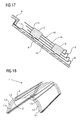
- FIG. 14 shows an example of such a cleaning device in longitudinal section, by multiple Abandoned and wrinkles produced 4 perforated layers. shown is a side of a ridge element that is symmetrical arranged opposite side is not shown in the picture.
- this type of design and Production also for other types of cleaning device used, for example, for similar configurations as in the previous figures.
- FIG. 1 A specific variant is shown in FIG a cleaning device 1 of 3 V-shaped folded and mated layers, of which perforated 2 layers are formed. As spacers act here the above-arranged bends, each on the support the lower layer and thus the distance and alignment determine the positions.
- Figure 16 shows a longitudinal section through a simple folded roof cleaning device 1, which is a kind of bag forms, in which an intermediate layer 1.3 with integrated spacers 2 is inserted.
- the liner is in the bottom Inserted into a groove area, here also as Spacer 2 is used. Additionally, they are located below in the folded bag forming the layers 1.1 and 1.3 small outlets 6, which store the stored liquid after appropriate reaction time and nachdrDeutschendem new Drain rainwater.
- FIG. 17 again shows a variant of a cleaning device on a flat roof surface with 4 layers 1.1 to 1.4 with lateral spacers 2 in longitudinal section.
- layers 1.2 to 1.4 are on each side two spacers attached, which themselves into the lower Location 1.1 are clipped.
- the lower layer 1.1 is through the ends of the holder 2 at a distance to the underlying Surface is held and is arranged with the above Tiles against slipping hooked.
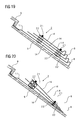
- a roof ridge element used as a roof cleaning device is designed and basically of its construction the cleaning device of FIG. 16 corresponds to FIG of Figure 18 shown in 3D representation as a wire model. These curved surfaces are also very easy and cost-effectively by punching method.
- Figures 19 and 21 show further exemplary embodiments the cleaning device according to the invention in particular to the variety of forms and execution of the spacers 2.
- Figure 19 shows a cleaning device similar to Figure 17, but here are the individual layers 1.x not the same length, but shorten from the bottom Position 1.1 up to the upper layer 1.4. This will achieve that in moderately to slightly occurring rain all Interspaces 14 between the layers even without openings in the surface of the layers are filled with moisture. This applies to both stable layers of sheet metal as well as layers made of flexible foil.
- Spacer 2 shown. These consist of one Combination of spacers 2.2 and one through the Spacer rings performed connecting element 2.1. For example can as spacers simple washers, Rings or wedges made of various materials like plastic, rubber or metal are taken.
- FIG. 20 shows how by different height spacers a conical Course of the layers 1.x can be reached.
- FIG correspondingly wide contact surface of the spacer elements 2.2 also sufficient to install only one spacer 2 per side, to achieve a sufficient fixation of the layers.
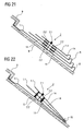
- the same is also in the figure 22 for a non-parallel course of the layers 1.x shown. additionally is here at the lower duck of the lower layer 1.1 still one - shown in chiselled - flanging or bevel 15 shown into which the upper layers can be inserted, to achieve additional fixation.
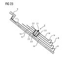
- the last figure 23 finally shows a further inventive Device in which by means of a punching process from the surface of the layers 1.2-1.4 integrated spacer elements 2.2 are withdrawn and not anymore must be used individually.
- a centering element 2.3 is inserted, at the same time as a kind of washer serves for the connection element 2.1.
- This can for example be made of plastic, or too designed as a metal sleeve with washer lying on top be.
- a Cleaning device disclosed which is suitable due to the most favorable moisture storage and at the same time strong enlargement of the reaction surface under different climatic conditions cleaning surfaces exposed to the weather cause.
- cleaning devices are not exclusive can serve for cleaning roofs, but in addition also clean other weathered surfaces, For example, this may be solar systems, Glass fronts, glass roofs or building facades act.
Landscapes
- Engineering & Computer Science (AREA)
- Biotechnology (AREA)
- Architecture (AREA)
- Civil Engineering (AREA)
- Structural Engineering (AREA)
- Life Sciences & Earth Sciences (AREA)
- Roof Covering Using Slabs Or Stiff Sheets (AREA)
- Cleaning In General (AREA)
- Cleaning By Liquid Or Steam (AREA)
- Forms Removed On Construction Sites Or Auxiliary Members Thereof (AREA)
- Photoreceptors In Electrophotography (AREA)
- Mechanical Treatment Of Semiconductor (AREA)
- Cleaning Of Streets, Tracks, Or Beaches (AREA)
- Cleaning And De-Greasing Of Metallic Materials By Chemical Methods (AREA)
Abstract
Description
Die Erfindung betrifft eine Reinigungsvorrichtung zum Aufbringen auf eine dem Wetter ausgesetzte Oberfläche, insbesondere ein Dach, eine Dachoberfläche, eine Solaranlagenoberfläche oder eine Fassade, wobei die Vorrichtung eine Vielzahl von Reaktionsflächen aufweist, die lagenweise angeordnet sind und eine metallische, vorzugsweise kupferhaltige, Oberfläche aufweisen, welche sich in Verbindung mit Wasser reinigende, vorzugsweise fungizide und/oder bakterizide, Verbindungen erzeugen, die in Wasser gelöst das Dach zumindest teilweise benetzen können.The invention relates to a cleaning device for applying on a surface exposed to the weather, in particular a roof, a roof surface, a solar system surface or a facade, wherein the device has a Has a variety of reaction surfaces arranged in layers are and a metallic, preferably copper-containing, Have surface, which in conjunction with Water-cleaning, preferably fungicidal and / or bactericidal, producing compounds that dissolved in water at least partially wet the roof.
Reinigungsvorrichtungen für Dächer und damit für dem Wetter ausgesetzte Oberflächen sind allgemein bekannt. Insbesondere wird auf die Patentschrift DE 100 58 855 C1 hingewiesen. Diese Patentschrift beschreibt ein Dachfirstelement aus Kupfer, welches parallel zu den Seitenflächen ein Feuchtigkeit führendes Kapillarblech aufweist, welches eine Kapillarspalte erzeugen soll und damit Wasser, welches in einer unten angeordneten Blechaufkantung sich sammelt, mit Hilfe einer Kapillarwirkung zwischen den eng aneinander liegenden, den Kapillarspalt bildenden Wänden nach oben gesaugt werden soll.Cleaning devices for roofs and thus for the weather exposed surfaces are well known. Especially Reference is made to the patent DE 100 58 855 C1. This patent describes a roof ridge element Copper, which parallel to the side surfaces of a moisture leading capillary plate which has a capillary gap should generate and thus water, which in one below arranged Blechaufkantung collects, with the help a capillary action between the close-fitting, The capillary gap forming walls sucked upwards shall be.
Das Problem dieser Vorrichtung besteht darin, dass zur Ausbildung eines solchen Kapillarspaltes eine sehr genaue Fertigung vorliegen muss, um die Kapillarwirkung über eine größere Region etwa gleich zu halten, wobei jedoch die Kapillarwirkung zwar dafür sorgt, dass etwas Wasser zwischen die Spalte eingesogen wird, jedoch ist ein Durchfluss des Wassers durch die Kapillarspalte nicht möglich, da aufgrund der Oberflächenspannung ein Zufuhrwiderstand für das durchfliesende Wasser entsteht, so dass nur ein ungenügender Wasseraustausch zwischen den Kapillarspalten und der Umgebung entsteht, wodurch möglicherweise gebildete Substanzen innerhalb des Kapillarspaltes nicht ausreichend nach außen treten können. Im Übrigen haben praktische Versuche mit derartigen eng aneinander angeordneten Kapillarspalten ergeben, dass nur eine ungenügende Verwitterung der Materialoberflächen entsteht, wodurch die Ausbildung von reinigenden Substanzen letztendlich verhindert wird.The problem of this device is that for training such a capillary gap a very accurate production must be present to the capillary action over a Larger region to keep about the same, but the capillary action while ensuring that some water is between the column is sucked in, however, is a flow of Water through the capillary column is not possible because due the surface tension is a feed resistance for the flowing through Water is produced, leaving only an insufficient Water exchange between the capillary gaps and the environment arises, possibly resulting in the formation of substances not sufficiently outward within the capillary gap can occur. Incidentally, have practical experiments with give such closely spaced capillary gaps, that only an insufficient weathering of the material surfaces arises, which reduces the formation of cleansing Ultimately, substances are prevented.
Weiterhin wird auf die Gebrauchsmusterschrift DE 201 04 999 U1 hingewiesen. Diese Gebrauchsmusterschrift offenbart ebenfalls ein metallisches Dachfirstelement, welches vorzugsweise aus Kupferblechen hergestellt wird, wobei über die Länge des Dachfirstelementes eine Kammer ausgebildet wird, welche auf der Unterseite durch ein durchgehendes Blech begrenzt wird und auf der Außenseite ein Gitter aufweist, welches eine Oberflächen vergrößernde Wirkung erzielen soll. Aufgrund der symmetrischen Ausgestaltung des Firstelementes wird auf beiden Seiten des Daches jeweils eine Kammer gebildet, die entsprechend dem dort beschriebenen Erfindungsgedanken auch durch ein Feuchtigkeit speicherndes Vlies oder Geflecht gefüllt werden kann. Praktische Versuche mit einer derartigen Ausführung einer Firsthaube haben ergeben, dass in der derart ausgebildeten Kammer kein ausreichendes Speichervolumen besteht, wobei obendrein die Speicherdauer für natürliches Wasser äußerst gering ist, da eine wesentlich zu frühe Verdunstung eventueller Feuchtigkeit auftritt.Furthermore, the utility model DE 201 04 999 U1 pointed out. This utility model also discloses a metallic roof ridge element, which preferably is made of copper sheets, with over the length of the roof ridge element is a chamber which is on the bottom by a through Sheet is limited and has a grid on the outside, which achieve a surface-enlarging effect should. Due to the symmetrical design of the Firstelementes will be on both sides of the roof respectively a chamber formed according to that described there The idea of the invention also by a moisture-storing Fleece or braid can be filled. practical Experiments with such a design of a ridge hood have shown that in the thus formed chamber there is no sufficient storage volume, and on top of that the storage time for natural water extremely low is because a much too early evaporation eventual Moisture occurs.
Es ist daher Aufgabe der Erfindung, eine Reinigungsvorrichtung zum Aufbringen auf eine dem Wetter ausgesetzte Oberfläche oder ein Dach zu finden, welche eine gegenüber den oben geschilderten Vorrichtungen verbesserte Wirkung bei der Oberflächenreinigung aufweist.It is therefore an object of the invention to provide a cleaning device for application to a surface exposed to the weather or to find a roof, which is opposite to the one above-described devices improved effect the surface cleaning has.
Der Erfinder hat erkannt, dass zur Verbesserung der selbstreinigenden Wirkung von Reinigungsvorrichtungen zum Aufbringen auf eine dem Wetter ausgesetzten Oberfläche es wesentlich ist, eine optimale Kombination zwischen der aufgefangenen und gespeicherten Feuchte und der zur Verfügung gestellten Reaktionsfläche des Metalls, insbesondere des Kupfers, notwendig ist, wobei zusätzlich dafür Sorge zu tragen ist, dass auch eine ausreichende Abflussmöglichkeit der zwischenzeitlich gespeicherten Flüssigkeit notwendig ist, sobald eine neue Wasserzufuhr, also neuer Regen, auftritt. Hierbei erscheint es außerdem wesentlich, dass die Ausgestaltung der Reinigungsvorrichtung, insbesondere der Kammern, in denen die Feuchtigkeit zurückerhalten wird, so gestaltet sein kann, dass die außen auftreffende Sonnenstrahlung die Innenkammern nicht zu sehr erwärmt, um ein frühzeitiges Verdunsten der Feuchtigkeit aus den Kammern zu vermeiden.The inventor has realized that to improve self-cleaning Effect of cleaning devices for application on a surface exposed to the weather it essential is, an optimal combination between the trapped and stored humidity and the available Asked reaction surface of the metal, in particular the Copper, which is necessary, in addition to take care wear is that also a sufficient drainage possibility the liquid stored in the meantime necessary is as soon as a new water supply, so new rain, occurs. It also seems essential that the Embodiment of the cleaning device, in particular the Chambers in which the moisture is recovered, so can be designed that the outside impinging solar radiation the inner chambers are not too much warmed to one early evaporation of moisture from the chambers too avoid.
Neben der Notwendigkeit eines ausreichenden Wasserdurchflusses ist es auch notwendig durch ausreichenden Abstand der Lagen zueinander dafür zu sorgen, dass die Oberflächen oder auch Reaktionsflächen ausreichend mit Luft in Berührung kommen, um eine genügende Verwitterung der Oberfläche zu erzeugen, da diese Voraussetzung für die Wirksamkeit der Reinigungsvorrichtung ist. Sehr geringe Abstände zwischen den Lagen in einem Bereich, in dem Kapillarkräfte zwischen den Lagen wirksam werden, sind ungünstig. Es sollten Abstände gewählt werden, die nach vertretbarer Zeit, eine ausreichende Verwitterung der Oberflächen aufweisen lassen. In addition to the need for adequate water flow it is also necessary by sufficient distance the layers to each other to ensure that the surfaces or reaction surfaces sufficiently in contact with air come to a sufficient weathering of the surface because this condition for the effectiveness of Cleaning device is. Very small distances between the layers in an area where capillary forces between the layers are effective, are unfavorable. It should be distances be elected after a reasonable time, one have sufficient weathering of the surfaces exhibit.
Demgemäß schlägt der Erfinder vor, die an sich bekannte Reinigungsvorrichtung zum Aufbringen auf eine dem Wetter ausgesetzte Oberfläche, insbesondere ein Dach, eine Dachoberfläche, eine Solaranlagenoberfläche oder eine Fassade, zu verbessern, wobei die Reinigungsvorrichtung eine Vielzahl von Reaktionsflächen aufweist, die lagenweise angeordnet sind und eine metallische, vorzugsweise kupferhaltige Oberfläche aufweist, welche in Verbindung mit Wasser reinigende, vorzugsweise fungizide und/oder bakterizide Verbindungen erzeugen, die im Wasser gelöst das Dach zumindest teilweise benetzen können. Erfindungsgemäß liegt die Verbesserung darin, dass mindestens eine obere Lage, eine untere Lage und mindestens eine Zwischenlage vorgesehen sind, wobei zumindest zwei Lagen zumindest über einen Teilbereich ihrer Fläche durch Abstandshalter derart voneinander getrennt sind, dass zwischen den Lagen Räume gebildet werden, in welche natürliche Feuchte, insbesondere Regenwasser, einfliesen und wieder ausgespült werden kann.Accordingly, the inventor proposes the per se known Cleaning device for applying to a weather exposed surface, in particular a roof, a roof surface, a solar system surface or a facade, to improve, the cleaning device a variety of reaction surfaces arranged in layers are and a metallic, preferably copper-containing Having surface which cleans in conjunction with water, preferably fungicidal and / or bactericidal compounds generate that dissolved in the water at least the roof can partially wet. According to the invention, the improvement lies in that at least one upper layer, one lower layer Position and at least one intermediate layer are provided, wherein at least two layers at least over a partial area their area separated by spacers are that spaces are formed between the layers in which natural moisture, especially rainwater, tile in and can be rinsed out again.
Durch diese Ausgestaltung wird das auftretende Wasseraufkommen gezielt auf mehrere Feuchtigkeitsebenen, die durch Abstandshalter gebildet werden verteilt, wobei die in diesen Kammern gespeicherte Feuchtigkeit aufgrund der darüber liegenden Lagen beispielsweise durch Sonneneinstrahlung relativ wenig erwärmt wird, insbesondere wenn die Abstandshalter die benachbarte Fläche nur nahezu punktförmig berührein, so dass der gespeicherten Feuchte ausreichend Zeit zur Verfügung gestellt wird, mit der metallischen, vorzugsweise vergitterten Oberfläche, zu reagieren und die für die reinigende Wirkung notwendige Substanzen aus der metallischen Oberfläche, die die Reaktionsfläche bildet, herauszulösen. Außerdem ist durch die erfindungsgemäße Ausgestaltung gewährleistet, dass bei neu auftretendem Wasser eine möglichst ungehinderte Durchspülung dieser Kammern erfolgt, so dass die dort gebildeten Substanzen ungehindert nach außen geschwemmt werden können und auf der zu reinigenden Oberfläche ihre Wirkung entfalten können.By this configuration, the occurring water is targeted to multiple levels of moisture through Spacers are formed distributed, with the in these Chambers stored moisture due to the above lying layers, for example, by sunlight relative little is heated, especially if the spacers the neighboring area only touches almost point-like, allowing the stored moisture sufficient time for Is made available with the metallic, preferably latticed surface, to respond and for the cleansing Effect necessary substances from the metallic Surface, which forms the reaction surface to dissolve. In addition, it is ensured by the inventive design, that with newly occurring water one possible unimpeded flushing of these chambers takes place, so that the substances formed there freely to the outside can be washed and on the surface to be cleaned to be effective.
Obwohl es nicht unbedingt notwendig ist, kann es doch sehr vorteilhaft sein, zumindest die äußere Lage mit einer Vielzahl von Durchbrüchen zu versehen, so dass auch auf der Oberfläche der Reinigungsvorrichtung auftreffender Regen relativ ungehindert an die Unterseite der jeweiligen Lage durchdringen kann. Entsprechend kann nicht nur die äußere Lage sondern auch die darunter angeordneten Zwischenlagen und gegebenenfalls sogar die untere Lage mit Durchbrüchen versehen sein, um auch dort eine Durchlässigkeit zu erzeugen, wobei die Durchbrüche jedoch ausreichend klein sein sollten um ein einfaches Durchschießen von Flüssigkeit zu verhindern. Es muss also ein Kompromiss zwischen Speicherwirkung und Behinderung des Durchflusses von Flüssigkeit erreicht werden.Although it is not absolutely necessary, it can be very be advantageous, at least the outer layer with a variety provided by breakthroughs, so that too on the surface the cleaning device incident rain relative unhindered to the bottom of each layer can penetrate. Accordingly, not only the outer one Location but also the underlying layers and possibly even the lower layer with breakthroughs be provided in order to produce a permeability there, however, the breakthroughs should be sufficiently small should be for easy shooting through of liquid too prevent. So there has to be a compromise between storage effect and obstruction of the flow of fluid be achieved.
Zum Erreichen dieses Zieles können die einzelnen Lagen zueinander parallel oder auch konisch angeordnet sein, wobei es besonders vorteilhaft ist, wenn sich der Abstand zwischen den einzelnen Lagen nach oben hin vergrößert. Vorteilhaft ist es auf jeden Fall, wenn die Fläche aus der Summe der Eintrittsöffnungen größer ist als die Fläche der Summe der Austrittsöffnungen.To achieve this goal, the individual layers to each other be arranged parallel or conical, wherein it is particularly advantageous if the distance between enlarged the individual layers upwards. Advantageous It is definitely when the area is out of the Sum of the inlet openings is greater than the area of Sum of the outlet openings.
Die Abstandshalter zwischen den Lagen können beispielsweise so gestaltet sein, dass sie möglichst punktförmig oder höchstens linienförmig die in Abstand zu haltenden Flächen berühren, wobei darauf hinzuweisen ist, dass es sich bei den Abstandshaltern nicht unbedingt um einzelne separate Elemente handeln muss, sondern dass die beschriebenen Lagen durch Stanzwerkzeuge hergestellt werden können und hierbei durch entsprechende Formgebung der Oberfläche und gegebenenfalls Herausschneiden von Öffnungen die Abstandshalter in die Oberfläche der einzelnen Lagen integriert werden können. Den Formgestaltungen der Abstandshalter ist dabei kaum eine Grenze gesetzt, wobei es jedoch vorteilhaft ist, wenn jeweils eine möglichst starke Vergrößerung der reaktiven Oberfläche durch solche Abstandshalter erfüllt wird.The spacers between the layers can, for example be designed so that they are as punctiform or at most in a line the areas to be kept apart It should be noted that it is the spacers are not necessarily separate Elements must act, but that the layers described can be produced by punching tools and this by appropriate shaping of the surface and optionally Cut out the openings of the spacers integrated into the surface of the individual layers can. The shape of the spacers is here barely set a limit, but it is advantageous if in each case the highest possible increase in the reactive Surface is satisfied by such spacers.
Eine weitere Ausbildung der Reinigungsvorrichtung sieht erfindungsgemäß vor, dass mindestens eine unten angeordnete Lage für mindestens eine darüber angeordnete Lage eine Wulst und/oder ein Scharnier aufweist, der die mindestens eine darüber angeordnete Lage endseitig, vorzugsweise zumindest abschnittsweise, linienförmig stützt. Eine solche Ausbildung ermöglicht es mehrere Lagen übereinander zu legen, wobei die ausgebildeten Wulste jeweils die darüber angeordneten Lage vor dem Herabrutschen schützen, beziehungsweise falls zwischen den Lagen ein Scharnier vorgesehen ist, auch ein Aufklappen der einzelnen Lagen ermöglicht wird. Da die erfindungsgemäße Reinigungsvorrichtung der äußeren Witterung und damit auch der Verschmutzung durch Staub oder Ablagerung von Blättern nahe stehender Bäume ausgesetzt ist, kann es vorteilhaft sein, die einzelnen Lagen auseinander zu nehmen beziehungsweise aufzuklappen und damit eine Reinigung in den Zwischenbereichen durchführen zu können. Zusätzlich ergibt sich die Möglichkeit durch ein konisches Aufklappen der einzelnen Lagen auch eine Schneerutschsicherung zu erzeugen, sobald sich auf einem schrägen Dach liegender Schnee in Bewegung setzt, so dass dieser durch sich aufspreizende Lagen der Reinigungsvorrichtung gebremst wird.A further embodiment of the cleaning device according to the invention before that at least one below arranged Location for at least one location above it Has bead and / or a hinge, the at least an overlying layer end, preferably at least sections, linear supports. Such Training allows you to overlay several layers wherein the formed beads each arranged above Protect the situation from slipping, respectively if provided between the layers of a hinge is, even a folding of the individual layers allows becomes. Since the cleaning device according to the invention the outer Weather and thus pollution by Dust or deposit of leaves of nearby trees exposed, it may be advantageous to the individual layers take apart or unfold and thus carry out a cleaning in the intermediate areas to be able to. In addition, the possibility arises through a conical opening of the individual layers also a Schneerutschsicherung to produce, once on a sloping Roof lying snow sets in motion, so this one by spreading layers of the cleaning device is slowed down.
Die erfindungsgemäße Reinigungsvorrichtung kann den verschiedensten Formen von Dächern und Oberflächen angepasst werden, wobei beispielsweise eine solche Reinigungsvorrichtung auch als Dachfirst oder Dachfirstabdeckung ausgebildet sein kann. Außerdem kann die Kontur und/oder die Oberfläche der Reinigungsvorrichtung an die Konturen und/oder Oberflächen von bekannten Dachplatten und Dachziegel angepasst werden. Bezüglich der möglichen Formen von Dachplatten, Dachziegeln oder sonstigen Dachabdeckungen oder Oberflächen wird beispielhaft auf die Internetseiten www.braas.de oder www.creaton.de hingewiesen. Insbesondere ist auch anzumerken, dass die Dachreinigungsvorrichtung der genannten Art ebenso auf Reetdächern oder Dächern, die mit Schiefer, Dachpappe, Welleternitplatten oder ähnlichem gedeckt sind, verwendet werden können, wobei insbesondere auch eine Anwendung für Solaranlagen oder sonstigen Glas- oder Kunststoffbedachungen möglich ist.The cleaning device according to the invention can be adapted to the most diverse forms of roofs and surfaces, wherein, for example, such a cleaning device can also be designed as a roof ridge or Dachfirstabdeckung. In addition, the contour and / or the surface of the cleaning device can be adapted to the contours and / or surfaces of known roof tiles and roof tiles. With regard to the possible shapes of roof tiles, roof tiles or other roof coverings or surfaces, the website www.braas.de or www.creaton.de is an example. In particular, it should also be noted that the roof cleaning device of the type mentioned can also be used on thatched roofs or roofs that are covered with slate, roofing felt, Welleternitplatten or the like, in particular, an application for solar systems or other glass or Kunststoffbedachungen is possible.
Bezüglich der Anzahl der vorhandenen Zwischenlagen hat sich in der Region Bayern besonders günstig die Anzahl von zwei Zwischenlagen, insgesamt also vier Lagen herausgestellt, allerdings kann es auch ausreichend sein, wenn die Reinigungsvorrichtung nur eine Zwischenlage, also insgesamt drei Lagen aufweist. Zur Optimierung des Abstandes der einzelnen Lagen kann es hierbei vorteilhaft sein, die Abstände der Einzellagen nicht gleich zu halten, sondern unterschiedliche hohe Zwischenräume zu erzeugen, so dass eine möglichst optimale Wasserrückhaltung je nach den gegebenen Witterungsverhältnissen bestimmter Regionen ermöglicht wird.Regarding the number of existing liners has become in the region of Bavaria particularly favorable the number of two Intermediate layers, a total of four layers, However, it may also be sufficient if the cleaning device only one intermediate layer, so a total of three Has layers. To optimize the distance of the individual Layers, it may be advantageous here, the distances of the Single layers not to keep the same, but different to create high spaces, so that as possible optimal water retention depending on the given weather conditions certain regions.
Weiterhin hat es sich als vorteilhaft herausgestellt, wenn zumindest zwischen zwei Lagen, vorzugsweise zwischen allen Lagen der Wassereintrittsspalt, d.h. der Spalt der Lagen, der der Wasserflussrichtung entgegen gerichtet ist, größer ist als der Wasseraustrittsspalt, d.h. der Spalt, aus dem das Regenwasser bei eingebautem Zustand der Reinigungsvorrichtung austritt; meist ist dies die untere Kante der einzelnen Lagen.Furthermore, it has proved to be advantageous if at least between two layers, preferably between all If the water entrance slit, i. the gap of the layers, the water flow direction is opposite, larger is considered the water exit slit, i. the gap from the the rainwater when the cleaning device is installed exit; Usually this is the bottom edge of each one Documents.
Eine weitere Verbesserung der Effektivität der Reinigungsvorrichtung kann dadurch erreicht werden, dass in den von den Lagen gebildeten Räumen, Kupfermaterial mit stark vergrößerter Oberfläche, vorzugsweise ein Granulat und/oder Flocken und/oder Geflecht und/oder Gewölle und/oder Fasern aus Kupfer und/oder Sinterstücke angeordnet sind. Durch die Verwendung derartiger oberflächenvergrößernder Mittel wird die zur Verfügung gestellte Reaktionsfläche stark erweitert, so dass eine größere Effektivität der Reinigungsvorrichtung möglich ist.A further improvement in the effectiveness of the cleaning device can be achieved in that of the The layers formed spaces, copper material with greatly enlarged Surface, preferably granules and / or Flakes and / or braid and / or casings and / or fibers made of copper and / or sintered pieces are arranged. By the Use of such surface enlarging agent is the reaction surface provided greatly expanded, allowing a greater effectiveness of the cleaning device is possible.
Die einzelnen Lagen können seiten- und/oder höhenversetzt zueinander angeordnet werden. Außerdem können die Lagen an zwei gegenüberliegenden Enden Auf- und/oder Abkantungen aufweisen. Die Lagen können einzeln lose aufeinander liegen oder zumindest die äußere und untere Lage, vorzugsweise alle Lagen, untereinander verbunden sein, wobei bekannte Verbindungstechniken wie Schrauben, Nägel, Nieten, Schweißverbindungen oder Klebeverbindungen anwendbar sind. Zumindest die untere Lage, vorzugsweise alle Lagen, können der dreidimensionalen Oberflächenform von Dachabschnitten und/oder Dachziegeln und/oder Solaranlagen oder sonstigen der Witterung ausgesetzten Oberflächen angepasst werden. Zur sicheren Befestigung der Reinigungsvorrichtung kann zumindest die untere Lage Befestigungselemente und/oder Befestigungsklammern aufweisen. Derartige Befestigungselemente können zumindest teilweise aus Kunststoff bestehen und in mindestens eine der Lagen, vorzugsweise die untere Lage, einclipsbar ausgestattet sein.The individual layers can be laterally and / or vertically offset be arranged to each other. In addition, the layers can two opposite ends up and / or bends exhibit. The layers can be individually loose or at least the outer and lower layers, preferably all Layers to be interconnected using known joining techniques like screws, nails, rivets, welded joints or adhesive joints are applicable. At least the lower layer, preferably all layers, the three-dimensional Surface shape of roof sections and / or Roof tiles and / or solar systems or other of the weather exposed surfaces are adjusted. For sure Attachment of the cleaning device can at least the lower layer fasteners and / or mounting brackets exhibit. Such fasteners can at least partially made of plastic and in at least one of the layers, preferably the lower layer, clipped be equipped.
Eine besondere Ausstattung der Abstandshalter kann darin bestehen, dass diese geflecht- und/oder gewebeartig ausgebildet sind, so dass die Lagen untereinander federnd auf Abstand gehalten werden und gleichzeitig jedoch möglichst geringe Wärmeflüsse zwischen den einzelnen Lagen entstehen.A special feature of the spacers can therein exist that this formed braid and / or tissue-like are, so that the layers are resilient to each other Keeping a distance and at the same time as possible low heat fluxes between the individual layers arise.
Erfindungsgemäß können diese Lagen aus einem Stück hergestellt werden, wobei hier vorzugsweise durch Abkanten und Falten die entsprechenden Zwischenräume erzeugt werden. According to the invention, these layers can be produced in one piece be here preferably by bending and Fold the corresponding spaces are generated.
Die einzelnen Lagen der Reinigungsvorrichtung können einerseits aus dünnem Blech, vorzugsweise Kupferblech hergestellt werden, andererseits besteht jedoch auch die Möglichkeit zumindest eine Lage der Reinigungsvorrichtung durch eine Folie, vorzugsweise eine Kupferfolie zu bilden. Werden alle Lagen der Reinigungsvorrichtung aus Folien gebildet, so hat dies den Vorteil, dass sich die Lagen sehr einfach der äußeren Kontur der jeweils bedeckten Dachziegel anpassen. In diesem Zusammenhang wird darauf hingewiesen, dass sich grundsätzlich sogenannte Folien von dünnen Blechen nicht unterscheiden. Im Sinne dieser Anmeldung wird allerdings unter einer Folie eine weitgehend flexible, sich durch das eigene Gewicht zumindest der großflächigen Kontur einer unter der Folie liegenden Gestalt eines Ziegels anpassende, Metallfläche gesehen. Ebenso ist dem Rahmen der Erfindung auch eine Folie oder Lage zuzurechnen, die aus mehreren Schichten aufgebaut ist, wobei nicht unbedingt alle Schichten metallisch sein müssen, sondern lediglich die der Feuchtigkeit zugängliche Schicht muss eine metallische Eigenschaft aufweisen, um die Reinigungswirkung zu erzeugen.The individual layers of the cleaning device can on the one hand made of thin sheet metal, preferably copper sheet On the other hand, there is also the possibility at least one layer of the cleaning device by a film, preferably a copper foil to form. If all layers of the cleaning device are formed from films, so this has the advantage that the layers are very simply the outer contour of each covered tile to adjust. In this context, it is pointed out that basically so-called films of thin sheets do not differ. For the purposes of this application but under a slide a largely flexible, itself by own weight at least the large-scale contour a shape of a brick lying under the film, Seen metal surface. Likewise, the framework of the Invention also attributable to a film or layer that made is built up of several layers, not necessarily all Layers must be metallic, but only the The moisture-accessible layer must be metallic Have property to produce the cleaning effect.
Eine vorteilhafte Ausgestaltung der Erfindung liegt auch darin, die Reinigungsvorrichtung mit mindestens einer Lage, vorzugsweise mit allen Lagen auszustatten, in deren Fläche Erhebungen und Vertiefungen eingeprägt sind, vorzugsweise kann dies durch Stanzen, insbesondere durch Rollwalzen, geschehen. In diesem Zusammenhang sei auch erwähnt, dass die Herstellung der erfindungsgemäßen Reinigungsvorrichtung durch mindestens einen Stanzvorgang besonders vorteilhaft sein kann. An advantageous embodiment of the invention is also therein, the cleaning device with at least one layer, preferably equipped with all layers in the area Elevations and depressions are impressed, preferably This can be done by punching, in particular by rolling rollers. In this context it should also be mentioned that the Production of the cleaning device according to the invention particularly advantageous by at least one punching operation can be.
Alternativ zu einer solchen Folie kann auch ein Geflecht oder Gewebe als Lage verwendet werden, ohne den Rahmen der Erfindung zu verlassen. Bei einer solchen Ausführung ist es Vorteilhaft, dass durch die aufgelockerte Struktur eines Gewebes oder Geflechts relativ zur Projektionsfläche sehr große mit Feuchtigkeit reagierende Oberflächen entstehen und damit die Wirksamkeit der Vorrichtung weiter verbessert werden können.Alternatively to such a film may also be a braid or tissue can be used as a layer without the scope of To leave invention. In such an embodiment, it is Advantageously, that the loosened structure of a Fabric or braid relative to the projection surface very much large surfaces react with moisture and thus further improves the effectiveness of the device can be.
Zusätzliche Merkmale und Vorteile der Erfindung ergeben sich aus der nachfolgenden Beschreibung bevorzugter Ausführungsbeispiele unter Bezugnahme auf die Zeichnungen und durch die Patentansprüche.Additional features and advantages of the invention will be apparent from the following description of preferred embodiments with reference to the drawings and by the claims.
Die Erfindung soll nachfolgend anhand der Zeichnungen näher erläutert werden. Es stellen im Einzelnen dar:
- Figur 1:
- Reinigungsvorrichtung für einen Dachfirstziegel im Längsschnitt;
- Figur 2:
- Reinigungsvorrichtung für einen Dachfirstziegel mit geteilten Lagen im Längsschnitt;
- Figur 3:
- Reinigungsvorrichtung zum Aufbringen auf einen Dachziegel im Längsschnitt;
- Figur 4:
- weitere Reinigungsvorrichtungen zum Aufbringen auf einen Dachziegel im Längsschnitt;
- Figur 5a-5d:
- verschiedene Konturen der Reinigungsvorrichtung im Querschnitt (=Schnitt in Firstrichtung);
- Figur 6a-6b:
- Aufsicht auf die Kontur erfindungsgemäßer Reinigungsvorrichtungen;
- Figur 7a-7c:
- unterschiedliche Konturen einer Reinigungsvorrichtung für einen Dachfirst im Längsschnitt;
- Figur 8:
- Reinigungsvorrichtung auf einer flachen Dachfläche mit 4 Lagen mit seitlichem Abstandshalter im Längsschnitt;
- Figur 9:
- Schnitt
A-A durch Figur 8; - Figur 10:
- Reinigungsvorrichtung auf einer flachen Dachoberfläche mit 4 konisch angeordneten Lagen mit seitlichem Abstandshalter im Längsschnitt;
- Figur 11:
- 3D-Darstellung mit Drahtmodel der Dachreinigungsvorrichtung aus Figur 8;
- Figur 12:
- 3D-Darstellung mit Drahtmodel der Dachreinigungsvorrichtung aus Figur 10;
- Figur 13:
- Querschnitt durch eine Dachreinigungsvorrichtung mit unterschiedlich ausgeführten Lagen;
- Figur 14:
- Längsschnitt durch eine gefaltete Dachreinigungsvorrichtung mit 4 perforierten Lagen;
- Figur 15:
- Längsschnitt durch eine Dachreinigungsvorrichtung mit 3 V-förmig gefalteten und zusammengesteckten Lagen, 2 Lagen perforiert;
- Figur 16:
- Längsschnitt durch eine einfach gefaltete Dachreinigungsvorrichtung mit eingesteckter perforierter Zwischenlage;
- Figur 17:
- Reinigungsvorrichtung auf einer flachen Dachfläche mit 4 Lagen mit seitlichen Abstandshaltern im Längsschnitt;
- Figur 18:
- Dachreinigungsvorrichtung ausgestaltet als Dachfirstelement in 3D-Darstellung als Drahtmodell;
- Figur 19-23:
- weitere Ausführungsvarianten von Dachreinigungsvorrichtungen und Abstandshaltern.
- FIG. 1:
- Cleaning device for a roof ridge tile in longitudinal section;
- FIG. 2:
- Cleaning device for a roof ridge tile with divided layers in longitudinal section;
- FIG. 3:
- Cleaning device for application to a roof tile in longitudinal section;
- FIG. 4:
- further cleaning devices for application to a roof tile in longitudinal section;
- FIGS. 5a-5d:
- different contours of the cleaning device in cross section (= cut in Firstrichtung);
- FIGS. 6a-6b:
- Top view of the contour of inventive cleaning devices;
- FIGS. 7a-7c:
- different contours of a cleaning device for a roof ridge in longitudinal section;
- FIG. 8:
- Cleaning device on a flat roof surface with 4 layers with lateral spacer in longitudinal section;
- FIG. 9:
- Section AA through Figure 8;
- FIG. 10:
- Cleaning device on a flat roof surface with 4 conical layers with lateral spacers in longitudinal section;
- FIG. 11:
- 3D representation with wire model of the roof cleaning device of Figure 8;
- FIG. 12:
- 3D representation with wire model of the roof cleaning device of Figure 10;
- FIG. 13:
- Cross section through a roof cleaning device with different layers executed;
- FIG. 14:
- Longitudinal section through a folded roof cleaning device with 4 perforated layers;
- FIG. 15:
- Longitudinal section through a roof cleaning device with 3 V-shaped folded and assembled layers, perforated 2 layers;
- FIG. 16:
- Longitudinal section through a simply folded roof cleaning device with inserted perforated intermediate layer;
- FIG. 17:
- Cleaning device on a flat roof surface with 4 layers with lateral spacers in longitudinal section;
- FIG. 18:
- Roof cleaning device configured as roof ridge element in 3D representation as a wire model;
- Figure 19-23:
- Further variants of roof cleaning devices and spacers.
Die Figur 1 zeigt eine erfindungsgemäße Reinigungsvorrichtung
zum Auflegen auf einen Dachfirstziegel 3. Die Reinigungsvorrichtung
besteht aus vier Lagen 1.1 - 1.4, die den
Dachfirstziegel 3 auf der Oberseite weitgehend umfassen,
wobei jede Lage sich über beide Seiten des Dachfirstziegels
erstreckt. Die einzelnen Lagen weisen hierbei gestanzte
Ausbuchtungen 2 auf, die als Abstandshalter zwischen den
einzelnen Lagen wirken. An der Unterseite der jeweiligen
Lagen sind Wulste 8 aufgekantet, gegen die sich die jeweils
darüber liegende Lage mit ihrer Längsseite abstützen kann.
Durch die Formgestaltung der einzelnen Lagen mit den dargestellten
Abstandshaltern werden zwischen den Lagen ausreichende
Räume 14 erzeugt, in die Regen- oder Tauwasser von
oben über Öffnungen 6 in die Lagen eindringen und sich in
den Zwischenräumen sammeln kann. Die Lagen sind dabei so
gestaltet, dass aufgrund der Abstandshalter nur ein sehr
geringer thermischer Kontakt zwischen ihnen besteht, so
dass auch Sonneneinstrahlung nicht zu einer schnellen Verdampfung
des in den Zwischenräumen 14 liegenden Wassers
führt, so dass ausreichend Zeit und Oberfläche zur Ausbildung
der chemischen Substanzen zur Verfügung steht, die zur
Dachreinigung führen. Auf der linken Seite der Abbildung
sind zusätzlich in den Zwischenräumen 14 Einlagen 7 gezeigt,
die aus kupferhaltigem Material oder Kupfer bestehen
und zusätzlich neben den Oberflächen der einzelnen Lagen
eine Vergrößerung der Reaktionsfläche bewirken und außerdem
eine gewisse Wasserrückhaltewirkung erzeugen. Außerdem sind
auf der linken Seite die Durchbrüche verstärkt dargestellt,
damit auftreffender Regen leicht die einzelnen Lagen durchdringen
kann.FIG. 1 shows a cleaning device according to the invention
for placing on a
Die Figur 2 zeigt eine ähnliche Reinigungsvorrichtung 1 auf
einem Dachfirstziegel 3, jedoch ist hier lediglich die untere
Lage 1.4 so ausgestaltet, dass sie den gesamten Dachfirstziegel
3 umfasst, während die darauf angeordneten weiteren
Lagen 1.1 - 1.3 ausschließlich seitlich angeordnet
sind und durch Verbindungselemente 5 in Form von Schrauben,
Nägeln, Nieten oder ähnlichem am Herunterrutschen gehindert
werden. Die Ausgestaltung der einzelnen Lagen entspricht
dabei im wesentlichen der Darstellung der Figur 1, wobei
auch hier zusätzlich zwischen den Lagen Einlagen beispielsweise
Kupferkörnungen, Gewölle, Sinterelemente, Geflechte
oder ähnliches in die Räume 14 zwischen den Lagen eingebracht
werden können.FIG. 2 shows a similar cleaning device 1
a
Die Figuren 3 und 4 zeigen zwei Reinigungsvorrichtungen 1,
die auf ebenen Dachziegeln 9 angeordnet sind, wobei diese
ebenfalls 4-lagig ausgebildet sind. Die Ausstattung der Lagen
entspricht den Figuren 1 oder 2, wobei auch hier wiederum
Zwischenräume 14 zwischen den einzelnen Lagen 1.1 -
1.4 erzeugt werden, in denen sich Feuchtigkeit speichern
kann.FIGS. 3 and 4 show two
Zusätzlich ist in der Figur 3 dargestellt, dass zwischen
der untersten Lage 1.4 und der darüber liegenden Zwischenlage
1.3 ein Gewebe eingezogen ist, welches zusätzlich eine
Wasserrückhaltefunktion und oberflächenvergrößernde Funktion
aufweist, wobei diese verwendete Einlage 7 sinnvollerweise
aus einem Kupfermaterial bestehen sollte, damit sich
vermehrt die gewünschten Reaktionsprodukte bilden können.
Hierbei ist darauf hinzuweisen, dass es günstiger ist, solche
Einlagen in den unteren Schichten unterzubringen, da
derartige Einlagen für einen vermehrten Wärmefluss zwischen
oberer und unterer Lage sorgen, der jedoch im Grunde unerwünscht
ist. Sind allerdings auf der Oberseite mehrere gut
thermisch getrennte Lagen bereits angeordnet, so überwiegt
der bevorzugte Effekt der Wasserspeicherung und Oberflächenvergrößerung
gegenüber der thermischen Leitung. In addition, it is shown in FIG
the lowest layer 1.4 and the overlying intermediate layer
1.3 a fabric is fed, which in addition a
Water retention function and surface enlarging function
has, which used
Die Figur 4 zeigt eine Variation der Lagen bezüglich ihrer
Abstandshalter dahingehend, dass die erste unten liegende
Lage 1.1 eben ausgeführt ist, über Abstandshalter 2 verfügt,
die aus gut isolierendem Kunststoff hergestellt sind,
so dass zwischen der unteren Lage 1.4 und der darüber liegenden
Lage 1.3 nur geringer thermischer Kontakt besteht.
Hierdurch wird auch die Wärme durch den darunter liegenden
Ziegel möglichst gering in die darüber liegenden Lagen eingeleitet.
Genauso wird die äußere Lage 1.1 von der darunter
liegenden Zwischenlage 1.2 ebenfalls durch eingeclipste,
aus Kunststoff bestehende Abstandshalter getrennt.FIG. 4 shows a variation of the layers with regard to their
Spacer in that the first one below
Position 1.1 is executed, has
Insgesamt entsteht hierdurch eine optimale Kombination zwischen
Wasserrückhaltung und gleichzeitiger Isolation gegen
einwirkende Sonneneinstrahlung von außen. Wird von oben
vermehrt Wasser an die Reinigungsvorrichtung zugeführt, so
kann das bisher gespeicherte Wasser durch die im tieferen
Bereich vorhandenen Schlitze oder Austrittsöffnungen 12 der
einzelnen Lagen oder zwischen den endständigen Auflagepunkten
der Lagen austreten und damit eine Reinigung des in
Flussrichtung liegenden Daches oder der sonstigen Oberflächen
bewirken.Overall, this creates an optimal combination between
Water retention and simultaneous isolation against
acting sunlight from the outside. Will from the top
Increased water supplied to the cleaning device, so
can the previously stored water by those in the deeper
Area existing slots or
Die in dieser Schrift dargestellten Reinigungsvorrichtungen stellen lediglich ausgewählte Beispiele dar, wobei zur einfacheren Darstellung auch einfache geometrische Formen gewählt wurden. Dies betrifft einerseits die Oberfläche auf der die Reinigungsvorrichtungen aufliegen, als auch die Struktur und Form der Abstandshalter, die selbstverständlich durch entsprechend ausgebildetes Stanzwerkzeug verschieden ausgeführt werden können, wobei unterschiedlichste Formen Verwendung finden können. Vorteilhaft ist es hierbei meist, wenn sich zumindest die untere Lage jeweils der Form der abgedeckten Oberfläche, insbesondere der darunter liegenden Ziegeln anpasst, wobei es allerdings auch hierbei teilweise vorteilhaft sein kann, wenn mit Abstandshaltern gegenüber der darunter liegenden, zu reinigenden Oberfläche gearbeitet wird. Die Ausgestaltung der Abstandshalter selbst, falls sie aus den einzelnen Lagen selbst geformt werden, kann besonders günstig sein, wenn sie zu großen zusätzlichen Oberflächen führen und gleichzeitig möglichst einen geringen Wärmeübergang zu der in Abstand zu haltenden nächsten Lage erzeugen.The cleaning devices shown in this document represent only selected examples, with the simpler Representation also chosen simple geometric shapes were. On the one hand, this affects the surface the rest of the cleaning devices, as well as the Structure and shape of the spacers, of course different by appropriately trained punch can be executed, with very different Forms can be used. It is advantageous here usually when at least the lower layer of each form the covered surface, especially the underlying Adapts bricks, although it does may be partially advantageous when using spacers opposite the underlying surface to be cleaned is working. The design of the spacers even if formed from the individual layers themselves can be particularly beneficial if they add too much extra Lead surfaces and at the same time as possible a low heat transfer to be kept in the distance Create next location.
Es wird darauf hingewiesen, dass insbesondere, jedoch nicht ausschließlich, die Ausführungsformen der Figuren 1 bis 4 dazu geeignet sind, auch durch relativ flexible Folien, insbesondere Kupferfolien, hergestellt zu werden, da sich besonders Folien dazu eignen durch Ausbildung einer Oberflächenstruktur mit Erhebungen oder Noppen trotz ihrer Flexibilität einen Abstand zwischen den Lagen zu halten, ohne dass eine Eigensteifigkeit notwendig wäre. Bezüglich der Verwendung solcher Folien ist es dann auch möglich individuelle Zuschnitte vor Ort vorzunehmen und sich damit zwanglos auf die Besonderheiten des jeweiligen Daches anzupassen.It should be noted that in particular, but not exclusively, the embodiments of Figures 1 to 4 are suitable, even by relatively flexible films, in particular copper foils, to be produced since especially films are suitable by forming a surface structure with elevations or dimples despite their flexibility to keep a distance between the layers without that an inherent rigidity would be necessary. Regarding the Using such films, it is also possible individual Make blanks on site and thus informal to adapt to the specifics of each roof.
Die Figuren 5a bis 5d zeigen Querschnitte durch mögliche Konturen der Reinigungsvorrichtung. So entspricht die Kontur der Figur 5a beispielsweise einer Frankfurter Pfanne, die Kontur der Figur 5b kann beispielsweise zur Verwendung auf einem Welleternitdach genutzt werden. Die Figuren 5c und 5d stellen einfache, leicht gebogene oder flache Konturen einer Reinigungsvorrichtung dar, wie sie auf relativ ebenen Oberflächen benutzt werden können. FIGS. 5a to 5d show cross sections through possible ones Contours of the cleaning device. This is how the contour corresponds FIG. 5a, for example, of a Frankfurt pan, For example, the contour of FIG. 5b may be used be used on a Welleternitdach. Figures 5c and 5d represent simple, slightly curved or flat contours a cleaning device as they are on relative flat surfaces can be used.
Selbstverständlich können des Weiteren alle bekannten Dachziegelkonturen und Konturen von allen bekannten Dachformen verwendet werden.Of course, furthermore, all known roof tile contours and contours of all known roof shapes be used.
Die Figuren 6a und 6b zeigen zwei beispielhafte Umrisse einer Dachreinigungsvorrichtung von oben gesehen, wobei die Figuren 7a bis 7c Längsschnitte quer zur Firstrichtung durch die Kontur von Reinigungsvorrichtungen zeigen, wie sie beispielsweise im Firstbereich verwendet werden.Figures 6a and 6b show two exemplary outlines of one Roof cleaning device seen from above, the FIGS. 7a to 7c are longitudinal cross-sectional views of the firing direction through the contour of cleaning devices show how they are used for example in the ridge area.
Mit der Figur 8 soll eine weitere Variante einer erfindungsgemäßen
Reinigungsvorrichtung dargestellt werden, die
hier auf einer Dachoberfläche mit flachen ebenen Dachziegeln
oder Dachsteinen 9 aufliegt. Die Reinigungsvorrichtung
verfügt über 4 Lagen Kupferblech, die durch seitlich angebrachte
Abstandshalter 2 die Lagen 1.1 bis 1.4 im wesentlichen
parallel fixieren.With the figure 8 is a further variant of an inventive
Cleaning device are presented, the
here on a roof surface with flat flat roof tiles
or
Die Anstandshalter können beispielsweise aus Kunststoff bestehen,
so dass nur eine geringe Wärmeübertragung zwischen
den Lagen besteht. Oben kann Regenwasser beim Ablaufen in
die gebildeten-Öffnungen 6 eindringen und wird zwischen den
Lagen 1.1 bis 1.4 in den Zwischenräumen 14 gespeichert, wo
ausreichend Zeit zur Reaktion mit der verwitterten Kupferoberfläche
besteht, damit die erforderlichen chemischen Reaktionen
stattfinden können. Im Endbereich der Reinigungsvorrichtung
sind durch das nicht vollständig dichte Aufeinanderstoßen
der Lagen Auslaufschlitze gebildet, über die
das angereicherte Wasser zur zu reinigenden Oberfläche austreten
kann. Zusätzlich können in diesem Bereich auch noch
Schlitze, kleine Öffnungen oder Perforationen im Endbereich
der jeweiligen Lage, vorzugsweise im Bereich des Wulstes 8
eingearbeitet sein, um den Wasseraustritt möglichst gleichmäßig
verteilt zu bewirken.The chamfers can be made of plastic, for example,
leaving little heat transfer between
the layers exists. Rainwater can leak up when running in
penetrate the formed
Der Schnitt A-A der Figur 8 ist in der Figur 9 dargestellt.
Hier ist besonders gut die Kontur der beispielhaften Abstandshalter
2 zu erkennen. Diese können einseitig oder
zweiseitig zur Fixierung der Lagen mit Schlitzen versehen
sein, in die die Lagen eingesteckt und damit in ihrem Abstand
fixiert werden. Alternativ zu den gezeigten konisch
ausgebildeten Schlitzen können diese auch parallel und
rechteckig ausgebildet sein.The section A-A of FIG. 8 is shown in FIG.
Here is particularly good the contour of the
In der hier gezeigten Ausbildungsform sind die Abstandshalter
so ausgeführt, dass sie auf der Oberfläche des Dachziegels
9 direkt aufliegen und auch die untere Lage in einem
Abstand zur Dachoberfläche halten, um für ausreichende Verwitterung
und den richtig dosierten Wasserdurchtritt zu erzeugen.
Die Abstandshalter sind hier mit Laschen 10 seitlich
an oder zwischen den Dachziegeln 9 befestigt. Zur Fixierung
zwischen Abstandshalter 2 und Lasche 10 wird hier-rechts
dargestellt - beispielsweise ein Befestigungselement
13 in Form eines Nagels, einer Schraube oder einer Niet
verwendet. Wie links gezeigt ist, greift die Lasche 10 in
einen Schlitz in dem Abstandshalter 2 ein. Zu erwähnen ist
noch, dass die Länge der einzelnen Lagen gleich ist und
sich daher in Längsrichtung ein Versatz um die Breite des
Wulstes 8 ergibt.In the embodiment shown here are the spacers
designed so that they are on the surface of the
Die Figur 10 zeigt eine Reinigungsvorrichtung auf einer
flachen Dachoberfläche 9 mit ebenfalls 4 Lagen mit seitlichem
Abstandshalter im Längsschnitt. Allerdings sind hier
die 3 oberen Lagen seitlich vollständig von den Abstandshaltern
2 eingefasst, wobei die Lagen nach unten konisch
aufeinander zulaufen. Durch die seitliche Einfassung wird
das Wasser in den von den Lagen gebildeten Räumen besonders
gut zurückgehalten. Die untere Lage 1.1 ist hier wesentlich
länger aus die restlichen Lagen ausgebildet und kann so
beispielsweise mit einem oberhalb angeordneten Ziegel verklemmt
oder verhakt werden.FIG. 10 shows a cleaning device on a
Des weiteren kann die gezeigte Abbildung auch lediglich als einseitiger Teil eines symmetrisch ausgebildeten Firstelementes betrachtet werden, bei dem die untere Lage 1.1 den Dachfirst umspannt oder sogar selbst bildet.Furthermore, the illustration shown can also only be used as one-sided part of a symmetrical ridge element considered, in which the lower layer 1.1 the Roof ridge covers or even forms itself.
Außerdem ist darauf hinzuweisen, dass diese Art der Ausführung, wenn sie in unteren Bereichen eines Daches angebracht wird, sich besonders gut als Schneebremse eignet oder zumindest dies Funktion zusätzlich übernimmt. Auch Kombinationen aus parallel und konisch angeordneten Lagen sind möglich.It should also be noted that this type of execution, when mounted in lower areas of a roof is particularly well suited as a snow brake or at least this function additionally takes over. Also combinations from parallel and conically arranged layers are possible.
Die Figur 11 zeigt zur besseren Anschauung eine 3D-Darstellung mit Drahtmodel der Dachreinigungsvorrichtung aus Figur 8, während die Figur 12 eine 3D-Darstellung der Dachreinigungsvorrichtung aus Figur 10 zeigt.FIG. 11 shows a 3D representation for a better view with wire model of the roof cleaning device from Figure 8, while the figure 12 is a 3D representation of Roof cleaning device of Figure 10 shows.
In der Figur 13 ist ein Querschnitt durch eine Dachreinigungsvorrichtung
ähnlich der Figuren 8 oder 10, jedoch mit
unterschiedlich ausgeführten Lagen gezeigt. Links ist die
untere Lage ohne Durchbrüche mit einer darüber liegenden
Sintereinlage gezeigt. Darüber befindet sich eine fein
perforierte Lage 1.2, darüber eine gröber perforierte Lage
1.3 gefolgt von der, mit großen Löchern oder Schlitzen 6
durchbrochenen oberen Lage 1.4. Zusätzlich ist zwischen
zwei Lagen ein elastisches Verbindungselement 11 - hier mit
Federelementen - angeordnet, welches ein
elementen - angeordnet, welches ein Auseinanderrutschen der
Abstandshalter 2 verhindert und damit hilft die Lagen sicher
zu verklemmen. Es ist darauf hinzuweisen, dass die Position
und Zahl der Verbindungselemente variiert werden
kann.In the figure 13 is a cross section through a roof cleaning device
similar to the figures 8 or 10, but with
shown differently executed layers. Left is the
lower layer without openings with an overlying one
Sintered insert shown. Above it is a fine
perforated layer 1.2, above a coarser perforated layer
1.3 followed by the one with big holes or
Die rechte Seite der Figur 13 zeigt eine andere Anordnung der Lagen 1.1 bis 1.4. Hier ist die obere Lage 1.4 geschlossen ausgebildet, darunter befindet sich eine stark strukturierte gleichmäßig dicke Sinterfläche 1.3, gefolgt von einer Sinterlage 1.2, die zentral dicker ausgebildet ist als am Rande, wiederum gefolgt von einer stark perforierten unteren Lage 1.1.The right side of Figure 13 shows another arrangement the layers 1.1 to 1.4. Here the upper layer 1.4 is closed trained, underneath is a strong structured uniformly thick sintered surface 1.3, followed from a sintered layer 1.2, which is formed centrally thicker is considered marginal, again followed by a strongly perforated one lower layer 1.1.
Es ist darauf hinzuweisen, dass aufgrund unterschiedlicher klimatischer Verhältnisse auch die optimale Anordnung der einzelnen Lagen variiert, wobei meist das Ziel der Anordnung ist, eine möglichst dauerhafte Wasserspeicherung gepaart mit guten Verwitterungsverhältnissen und guter Ausschwemmung der erzeugten Reaktionsprodukte zu erreichen.It should be noted that due to different climatic conditions also the optimal arrangement of individual layers varies, with usually the goal of the arrangement is, as long as possible water storage paired with good weathering conditions and good drainage reach the generated reaction products.
Erfindungsgemäß kann die Reinigungsvorrichtung aus einem
flachen Kupfermaterial gestanzt werden, wobei darauf hinzuweisen
ist, dass unter Stanzen alle Fertigungsverfahren zu
verstehen sind, die unter diesen Begriff fallen - siehe
hierzu beispielsweise DIN 9870 oder "Der Werkzeugbau",
1997, ISBN 3-8085-1202-4, insbesondere Kapitel 1 "Stanztechnik".
Die Figur 14 zeigt beispielhaft eine solche Reinigungsvorrichtung
im Längsschnitt, die durch mehrfaches
Abkannten und Falten 4 perforierte Lagen erzeugt hat. Dargestellt
ist eine Seite eines Firstelementes, die symmetrisch
angeordnete Gegenseite ist im Bild nicht gezeigt.
Selbstverständlich kann diese Art der Ausgestaltung und
Herstellung auch für andere Typen von Reinigungsvorrichtung
verwendet werden, beispielsweise für ähnliche Ausgestaltungen
wie in den vorangehenden Figuren.According to the invention, the cleaning device of a
flat copper material to be punched, pointing out
is that under punching all manufacturing processes too
understand that fall under this term - see
for example DIN 9870 or "Die Werkzeugbau",
1997, ISBN 3-8085-1202-4, in
Eine spezielle Variante ist in der Figur 15 gezeigt, die
eine Reinigungsvorrichtung 1 aus 3 V-förmig gefalteten und
zusammengesteckten Lagen zeigt, von denen 2 Lagen perforiert
ausgebildet sind. Als Abstandshalter fungieren hier
die oben angeordneten Abkantungen, die sich jeweils auf der
unteren Lage abstützen und damit den Abstand und Ausrichtung
der Lagen bestimmen.A specific variant is shown in FIG
a
Die Figur 16 zeigt einen Längsschnitt durch eine einfach
gefaltete Dachreinigungsvorrichtung 1, die eine Art Tasche
bildet, in die eine Zwischenlage 1.3 mit integrierten Abstandshalter
2 eingesteckt ist. Die Zwischenlage ist im unteren
Bereich in eine Nut gesteckt, die hier ebenfalls als
Abstandshalter 2 dient. Zusätzlich befinden sich unten in
der gefalteten Tasche, die die Lagen 1.1 und 1.3 bilden
kleine Auslauföffnungen 6, die die gespeicherte Flüssigkeit
nach entsprechender Reaktionszeit und nachdrängendem neuen
Regenwasser auslaufen lassen.Figure 16 shows a longitudinal section through a simple
folded
Die Figur 17 zeigt nochmals eine Variante einer Reinigungsvorrichtung
auf einer flachen Dachfläche mit 4 Lagen 1.1
bis 1.4 mit seitlichen Abstandshaltern 2 im Längsschnitt.
Zur besseren Fixierung der Lagen 1.2 bis 1.4 sind je Seite
zwei Abstandshalter angebracht, die selbst in die untere
Lage 1.1 eingeclipst sind. Die untere Lage 1.1 wird durch
die Enden der Halter 2 auf Abstand zur darunter liegenden
Oberfläche gehalten und ist mit dem oberhalb angeordneten
Dachziegel gegen Abrutschen verhakt. FIG. 17 again shows a variant of a cleaning device
on a flat roof surface with 4 layers 1.1
to 1.4 with
Ein Dachfirstelement, das als Dachreinigungsvorrichtung ausgestaltet ist und von seiner Konstruktion grundsätzlich der Reinigungsvorrichtung aus Figur 16 entspricht ist in der Figur 18 in 3D-Darstellung als Drahtmodell gezeigt. Auch diese gekrümmten Oberflächen lassen sich sehr leicht und kostengünstig durch Stanzverfahren herstellen.A roof ridge element used as a roof cleaning device is designed and basically of its construction the cleaning device of FIG. 16 corresponds to FIG of Figure 18 shown in 3D representation as a wire model. These curved surfaces are also very easy and cost-effectively by punching method.
Die Figuren 19 und 21 zeigen weitere beispielhafte Ausbildungen
der erfindungsgemäßen Reinigungsvorrichtung insbesondere
zur Formen- und Ausführungsvielfalt der Abstandshalter
2. So zeigt die Figur 19 eine Reinigungsvorrichtung
ähnlich der Figur 17, jedoch sind hier die einzelnen Lagen
1.x nicht gleich lang, sondern verkürzen sich von der unteren
Lage 1.1 bis zur oberen Lage 1.4. Hierdurch wird erreicht,
dass bei mäßig bis gering auftretendem Regen alle
Zwischenräume 14 zwischen den Lagen auch ohne Öffnungen in
der Fläche der Lagen mit Feuchtigkeit gefüllt werden. Dies
gilt sowohl für stabile Lagen aus Blech als auch für Lagen
aus flexibler Folie. Zusätzlich ist eine Variationen der
Abstandshalter 2 gezeigt. Diese bestehen hier aus einer
Kombination von Abstandselementen 2.2 und einem durch die
Abstandringe durchgeführten Verbindungselement 2.1. Beispielsweise
können als Abstandselemente einfache Zwischenscheiben,
Ringe oder auch Keile aus verschiedensten Materialien
wie Kunststoff, Gummi oder Metall genommen werden.Figures 19 and 21 show further exemplary embodiments
the cleaning device according to the invention in particular
to the variety of forms and execution of the
Werden, wie in der Figur 19 gezeigt, auf einer Seite gleich hohe Abstandselemente verwendet, so erhält man einen parallelen Lagenabstand. In der Figur 20 ist dargestellt, wie durch unterschiedlich hohe Abstandselemente ein konischer Verlauf der Lagen 1.x zu erreichen ist. Be as shown in Figure 19, on one side the same used high spacing elements, one obtains a parallel Location distance. FIG. 20 shows how by different height spacers a conical Course of the layers 1.x can be reached.
Vereinfachend ist in der Figur 21 dargestellt, dass es bei
entsprechend breiter Auflagefläche der Abstandselemente 2.2
auch ausreicht je Seite nur einen Abstandshalter 2 anzubringen,
um eine ausreichende Fixierung der Lagen zu erreichen.
Entsprechendes ist auch in der Figur 22 für einen
nicht-parallelen Verlauf der Lagen 1.x gezeigt. Zusätzlich
ist hier am unteren Ente der unteren Lage 1.1 noch eine -
gestichelt dargestellte - Umbördelung oder Abkantung 15 gezeigt,
in welche die oberen Lagen eingeschoben werden können,
um eine zusätzliche Fixierung zu erreichen.For simplicity, it is shown in FIG
correspondingly wide contact surface of the spacer elements 2.2
also sufficient to install only one
Die letzte Figur 23 zeigt schließlich eine weitere erfindungsgemäße Vorrichtung, in der mit Hilfe eines Stanzvorganges aus der Fläche der Lagen 1.2-1.4 integrierte Abstandselemente 2.2 herausgezogen sind und damit nicht mehr einzeln eingesetzt werden müssen. Im entstandenen Freiraum der Abstandselemente ist ein Zentrierelement 2.3 eingesetzt, das gleichzeitig auch als eine Art Unterlegscheibe für das Verbindungselement 2.1 dient. Dieses kann beispielsweise aus Kunststoff hergestellt werden, oder auch als Metallhülse mit oben liegender Unterlegscheibe ausgeführt sein. Grundsätzlich besteht eine Großzahl an verschiedenen distanzhaltenden Verbindungsmöglichkeiten der einzelnen Lagen, die alle im Rahmen der Erfindung liegen.The last figure 23 finally shows a further inventive Device in which by means of a punching process from the surface of the layers 1.2-1.4 integrated spacer elements 2.2 are withdrawn and not anymore must be used individually. In the resulting open space the spacer elements a centering element 2.3 is inserted, at the same time as a kind of washer serves for the connection element 2.1. This can for example be made of plastic, or too designed as a metal sleeve with washer lying on top be. Basically, there are a large number of different distance-maintaining connection possibilities of individual layers, all of which are within the scope of the invention.
Insgesamt ist noch darauf hinzuweisen, dass alle gezeigten und alle erfindungsgemäßen Reinigungsvorrichtungen sowohl eben als auch gewellt oder gekrümmt, sowohl in Längsrichtung als auch in Querrichtung ausgebildet sein können ohne den Rahmen der Erfindung zu verlassen. Ergänzend wird außerdem darauf hingewiesen, dass alle in den Ausführungsbeispielen gezeigten Lagen auch mit Erhebungen und Vertiefungen und/oder Öffnungen versehen sein können ohne den Rahmen der Erfindung zu verlassen.Overall, it should be noted that all shown and all cleaning devices according to the invention both just as well as wavy or curved, both longitudinally as well as be formed in the transverse direction without the To leave frame of the invention. In addition will be added noted that all in the embodiments shown positions also with elevations and depressions and / or openings may be provided without the frame of the To leave invention.
Bezüglich des in der Anmeldung angesprochenen Stanzverfahrens
wird darauf hingewiesen, dass hierunter alle Fertigungsverfahren
zu verstehen sind, die in der DIN 9870,
Blatt 1, Ausgabe Okt. 1974, einschließlich der dort in der
Alphabetischen Übersicht zitierten weiteren DIN-Blätter mit
gegebenenfalls weiteren Verweisen, genannt sind.With regard to the stamping process mentioned in the application
It should be noted that this includes all manufacturing processes
to be understood in the DIN 9870,
Insgesamt wird also durch die dargestellte Erfindung eine Reinigungsvorrichtung offenbart, welche geeignet ist aufgrund der besonders günstigen Feuchtigkeitsspeicherung und dabei gleichzeitig starken Vergrößerung der Reaktionsoberfläche unter unterschiedlichsten klimatischen Bedingungen die Reinigung von dem Wetter ausgesetzten Oberflächen zu bewirken. Diesbezüglich ist besonders darauf hinzuweisen, dass derartige Reinigungsvorrichtungen nicht ausschließlich zur Reinigung von Dächern dienen können, sondern zusätzlich auch sonstige der Witterung ausgesetzte Oberflächen reinigen, beispielsweise kann es sich hierbei um Solaranlagen, Glasfronten, Glasdächer oder auch Gebäudefassaden handeln. Overall, therefore, by the illustrated invention a Cleaning device disclosed which is suitable due to the most favorable moisture storage and at the same time strong enlargement of the reaction surface under different climatic conditions cleaning surfaces exposed to the weather cause. In this regard, it should be pointed out that such cleaning devices are not exclusive can serve for cleaning roofs, but in addition also clean other weathered surfaces, For example, this may be solar systems, Glass fronts, glass roofs or building facades act.
- 11
- Reinigungsvorrichtungcleaning device
- 1.X1.X
- Lagendocuments
- 22
- Abstandhalterspacer
- 2.12.1
- Abstandselementspacer
- 2.22.2
- Verbindungselementconnecting element
- 2.32.3
- Zentrierelementcentering
- 33
- DachfirstziegelRoof ridge tiles
- 4.X4.X
- Verbindungselementefasteners
- 55
- Nägel / SchraubenNails / screws
- 66
- Durchbrüche / Öffnungen / SchlitzeBreakthroughs / openings / slots
- 77
- Einlageninsoles
- 88th
- Wulst / AufkantungBead / upstand
- 99
- Dachziegeltile
- 1010
- Lascheflap
- 1111
- Verbindungselement / FederelementConnecting element / spring element
- 1212
- Auslaufspaltoutlet gap
- 1313
- Nagelnail
- 1414
- Zwischenraumgap
Claims (38)
- Cleaning device (1) for fitting to a surface exposed to the weather, in particular a roof, a roof surface, a solar system surface or a facade, the device having reactive surfaces, which are arranged in layers and have a metallic, preferably copper-containing, surface which, in conjunction with water, generate cleaning, preferably fungicidal and/or bactericidal compounds which, dissolved in water, can at least partly wet the roof, characterized in that at least one outer layer (1.n), a lower layer (1.1) and at least one intermediate layer (1.2 - 1.n-1) are provided, at least two layers being separated from each other, at least over a subregion of their area, by spacers (2) in such a way that spaces (14) are formed between the layers, into which natural moisture, in particular rainwater, can flow and can be rinsed out again.
- Cleaning device according to the preceding Patent Claim 1, characterized in that the outer layer (1.n) has a large number of apertures (6).
- Cleaning device according to one of the preceding Patent Claims 1 to 2, characterized in that the at least one metallic intermediate layer (1.2 - 1.n-1) has a large number of apertures (6).
- Cleaning device according to one of the preceding Patent Claims 1 to 3, characterized in that the at least one layer (1.1) arranged on the roof side has a large number of apertures (6).
- Cleaning device according to one of the preceding Patent Claims 1 to 4, characterized in that the at least two layers (1.x) are arranged parallel to one another with the aid of the spacers (2).
- Cleaning device according to one of the preceding Patent Claims 1 to 5, characterized in that the at least two layers (1.x) are arranged conically in relation to one another with the aid of the spacers (2).
- Cleaning device according to one of the preceding Patent Claims 1 to 6, characterized in that the spacers (2) between two layers touch a layer (1.x) only in the manner of a point or in the manner of a line.
- Cleaning device according to one of the preceding Patent Claims 1 to 7, characterized in that the spacers (2) represent part of a deformed layer (1.x) and are preferably produced by a punching tool.
- Cleaning device according to one of the preceding Patent Claims 1 to 8, characterized in that at least one layer (1.x) has a bead (8) and/or hinge for at least one layer (1.x+1) arranged above it, which supports the at least one layer (1.x+1) arranged above it at the ends, preferably at least sectionally in the manner of a line.
- Cleaning device according to one of the preceding Patent Claims 1 to 9, characterized in that it is formed as a roof ridge slab.
- Cleaning device according to one of the preceding Patent Claims 1 to 9, characterized in that its contour and/or surface are matched to known roof slabs and roof tiles.
- Cleaning device according to one of the preceding Patent Claims 1 to 11, characterized in that the spacers (2), at least in the upward region, effect a minimum spacing of preferably more than 1 mm, preferably 2 mm to 3 mm, in which capillary action with respect to penetrating water can be disregarded.
- Cleaning device according to one of the preceding Patent Claims 1 to 12, characterized in that at least two intermediate layers (1.2 - 1.n-1) are provided, preferably exactly two intermediate layers (1.2, 1.3).
- Cleaning device according to one of the preceding Patent Claims 1 to 13, characterized in that all the layers (1.x) are separated from one another by spacers (2).
- Cleaning device according to one of the preceding Patent Claims 1 to 14, characterized in that the spacers (2) have different heights.
- Cleaning device according to one of the preceding Patent Claims 1 to 15, characterized in that, at least between two layers, the water inlet gap (6) . is larger than the water outlet gap (12).
- Cleaning device according to one of the preceding Patent Claims 1 to 16, characterized in that copper material with a highly enlarged surface, preferably granules and/or flakes and/or a net and/or pellets and/or fibres made of copper and/or sintered pieces, is arranged in the spaces (14) formed by the layers.
- Cleaning device according to one of the preceding Patent Claims 1 to 17, characterized in that the layers are arranged to be offset laterally and/or vertically in relation to one another.
- Cleaning device according to one of the preceding Patent Claims 1 to 18, characterized in that the layers (1.x) have turned-up and/or turned-down edges at two opposite ends.
- Cleaning device according to one of the preceding Patent Claims 1 to 19, characterized in that at least the outer and lower layer (1.1, 1.n), preferably all the layers (1.x), are connected to one another, preferably by means of screws and/or nails (5) and/or rivets and/or welded connections and/or adhesive connections.
- Cleaning device according to one of the preceding Patent Claims 1 to 20, characterized in that the layers (1.x) are matched to the 3-dimensional surface shape of roof sections and/or roof tiles and/or solar systems.
- Cleaning device according to one of the preceding Patent Claims 1 to 21, characterized in that at least the lower layer (1.1) has fastening elements (5) and/or fastening clamps, with which they can be fastened to the surface to be cleaned.
- Cleaning device according to the preceding Patent Claim 22, characterized in that the fastening clamps and/or the fastening elements consist at least partly of plastic and are preferably clipped into at least one of the layers, preferably the lower layer.
- Cleaning device according to one of the preceding Patent Claims 1 to 23, characterized in that the spacers (2) have openings (6) towards the underside of the layer (1.x) which is oriented counter to the direction of flow of water.
- Cleaning device according to one of the preceding Patent Claims 1 to 24, characterized in that the spacers (2) and/or openings (6) in the layers are arranged to be offset from layer (1.x) to layer (1.x+1).
- Cleaning device according to one of the preceding Patent Claims 1 to 25, characterized in that the spacers (2) are produced at least partly from plastic.
- Cleaning device according to one of the preceding Patent Claims 1 to 23, characterized in that the spacers (2) are formed in the manner of nets and/or fabrics.
- Cleaning device according to one of the preceding Patent Claims 1 to 27, characterized in that at least two layers (1.x), preferably the outer and the lower layer, are produced from one piece.
- Cleaning device according to one of the preceding Patent Claims 1 to 28, characterized in that at least two layers (1.x), preferably all the layers, are produced from one piece, preferably by means of repeatedly turning down edges and folding.
- Cleaning device according to one of the preceding Patent Claims 1 to 29, characterized in that the layers (1.x) are at least partly curved in the longitudinal direction.
- Cleaning device according to one of the preceding Patent Claims 1 to 30, characterized in that the layers (1.x) are at least partly curved in the transverse direction.
- Cleaning device according to one of the preceding Patent Claims 1 to 31, characterized in that the spacers (2) are arranged at the sides of the layers.
- Cleaning device according to the preceding Patent Claim 32, characterized in that the spacers (2) extend over the entire length of the layers (1.x) and, at least for the most part, close off laterally the spaces (14) formed between the layers.
- Cleaning device according to one of the preceding Patent Claims 32 to 33, characterized in that lugs (10) are provided which fasten the spacers (2) to the roof and/or a roof covering and/or the lower layer (1.1).
- Cleaning device according to one of the preceding Patent Claims 32 to 34, characterized in that at least one connecting element (11), preferably a resilient connecting element, is provided between at least two spacers (2).
- Cleaning device according to one of the preceding Patent Claims 1 to 35, characterized in that lateral edgings are provided in order to form spaces in which the water is retained.
- Cleaning device according to one of the preceding Patent Claims 1 to 36, characterized in that at least one layer (1.x), preferably all the layers, consist of a foil.
- Cleaning device according to one of the preceding Patent Claims 1 to 37, characterized in that an elevations and depressions are embossed into at least one layer (1.x), preferably all the layers, by means of punching, in particular by means of roller rolling.
Applications Claiming Priority (2)
| Application Number | Priority Date | Filing Date | Title |
|---|---|---|---|
| DE20220561U | 2002-08-11 | ||
| DE20220561U DE20220561U1 (en) | 2002-08-11 | 2002-08-11 | Cleaning system, for surfaces exposed to weather, e.g. roofs and facades, has spaced metallic layers with a copper content to form zones to develop compounds against fungi and bacteria to be flushed over exposed areas |
Publications (2)
| Publication Number | Publication Date |
|---|---|
| EP1389659A1 EP1389659A1 (en) | 2004-02-18 |
| EP1389659B1 true EP1389659B1 (en) | 2005-03-16 |
Family
ID=30469930
Family Applications (1)
| Application Number | Title | Priority Date | Filing Date |
|---|---|---|---|
| EP03018007A Expired - Lifetime EP1389659B1 (en) | 2002-08-11 | 2003-08-07 | Cleaning device for surfaces exposed to the inclemency of weather |
Country Status (6)
| Country | Link |
|---|---|
| EP (1) | EP1389659B1 (en) |
| AT (1) | ATE291136T1 (en) |
| DE (2) | DE20220561U1 (en) |
| DK (1) | DK1389659T3 (en) |
| ES (1) | ES2240897T3 (en) |
| SI (1) | SI1389659T1 (en) |
Families Citing this family (4)
| Publication number | Priority date | Publication date | Assignee | Title |
|---|---|---|---|---|
| DE10352839B3 (en) * | 2003-11-10 | 2005-03-24 | Hugo Weber | Cleaning strip installed on roof, solar panel or facade, with bactericidal and fungicidal effect, has additional layers with moveable connection joining them to lower layer |
| WO2005071181A1 (en) | 2004-01-26 | 2005-08-04 | Hugo Weber | Cleaning device made of a copper sheet for weather exposed surfaces |
| EP1887159B1 (en) * | 2006-08-07 | 2009-06-03 | Hugo Weber | Weather independent cleaning device |
| CA2791532C (en) * | 2011-12-19 | 2015-04-14 | David Spencer | Shingle inserts and method for eliminating and preventing growth of algae, moss, or lichens on a roof |
Family Cites Families (4)
| Publication number | Priority date | Publication date | Assignee | Title |
|---|---|---|---|---|
| DE29804136U1 (en) * | 1998-03-09 | 1999-05-12 | Röhner, Horst, 91599 Dentlein | Partial roof protection cover or support as basic body, integrated lightning arrester with multilayer, permeable surface, pronounced areas against roof growth / cleaning |
| DE10058855C1 (en) | 2000-11-27 | 2002-04-04 | Hoesch Paul Michael | Ridge element, for building tiled roof, has moisture capture channel at bottom edge of each side surface and capillary sheet defining capillary gap with adjacent side surface |
| DE20104404U1 (en) * | 2001-03-14 | 2001-06-13 | Hepp, Edgar, 97901 Altenbuch | Ridge cover |
| DE20104999U1 (en) * | 2001-03-16 | 2001-05-23 | Vaclavik, Josef, 90763 Fürth | Device for removing vegetation on sloping roofs |
-
2002
- 2002-08-11 DE DE20220561U patent/DE20220561U1/en not_active Expired - Lifetime
-
2003
- 2003-08-07 EP EP03018007A patent/EP1389659B1/en not_active Expired - Lifetime
- 2003-08-07 SI SI200330037T patent/SI1389659T1/en unknown
- 2003-08-07 DK DK03018007T patent/DK1389659T3/en active
- 2003-08-07 AT AT03018007T patent/ATE291136T1/en not_active IP Right Cessation
- 2003-08-07 ES ES03018007T patent/ES2240897T3/en not_active Expired - Lifetime
- 2003-08-07 DE DE50300364T patent/DE50300364D1/en not_active Expired - Lifetime
Also Published As
| Publication number | Publication date |
|---|---|
| EP1389659A1 (en) | 2004-02-18 |
| DE50300364D1 (en) | 2005-04-21 |
| DE20220561U1 (en) | 2003-12-24 |
| SI1389659T1 (en) | 2005-10-31 |
| ATE291136T1 (en) | 2005-04-15 |
| ES2240897T3 (en) | 2005-10-16 |
| DK1389659T3 (en) | 2005-07-25 |
Similar Documents
| Publication | Publication Date | Title |
|---|---|---|
| DE60220760T2 (en) | solar panel | |
| WO1997037387A1 (en) | Bottom lining element for a flat, panel-shaped building element | |
| DE102005028830A1 (en) | Roofing and method therefor | |
| EP0724048B1 (en) | Rollable weatherstrip for ridge and/or roof edge covering | |
| EP1724508B1 (en) | Pipe | |
| AT390104B (en) | DREAM TRAINING | |
| EP1389659B1 (en) | Cleaning device for surfaces exposed to the inclemency of weather | |
| WO2004018793A1 (en) | Cleaning system designed to be installed on a surface exposed to poor weather conditions | |
| EP1228280B1 (en) | Ridge cover | |
| EP1306627A2 (en) | Device for using solar energy | |
| DE20221082U1 (en) | Cleaning assembly for glass roof, fascia or solar panels has rainwater traps discharging via copper blades onto glazing | |
| DE29604146U1 (en) | Sealing strips for a ridge and / or ridge cover | |
| EP3936680B1 (en) | Façade or roof lining with covering elements | |
| DE10352839B3 (en) | Cleaning strip installed on roof, solar panel or facade, with bactericidal and fungicidal effect, has additional layers with moveable connection joining them to lower layer | |
| DE19734346A1 (en) | Watertight flashing for sealing aperture in roof of building | |
| DE10105126C1 (en) | Cover grid for floor pan of floor-level convector has acute angled web and wall sectors and at least one wall sector with apertures | |
| DE29722219U1 (en) | Slat for a sun and / or heat protection system | |
| EP4093915B1 (en) | Functional module covered in greenery, building and noise barrier | |
| EP0182819A1 (en) | False ceiling for workstations | |
| DE2642999B1 (en) | Self-tensioning wall cladding panel | |
| EP3680413B1 (en) | Assembly with an extruded roof covering element | |
| DE29623686U1 (en) | Rollable sealing strip for a ridge and / or ridge cover | |
| EP1074673B1 (en) | Flexible eaves sealing element | |
| AT407174B (en) | EDGE STRIPS ON ROOF ELEVAS | |
| EP1191160A1 (en) | Floor drain |
Legal Events
| Date | Code | Title | Description |
|---|---|---|---|
| PUAI | Public reference made under article 153(3) epc to a published international application that has entered the european phase |
Free format text: ORIGINAL CODE: 0009012 |
|
| AK | Designated contracting states |
Kind code of ref document: A1 Designated state(s): AT BE BG CH CY CZ DE DK EE ES FI FR GB GR HU IE IT LI LU MC NL PT RO SE SI SK TR |
|
| AX | Request for extension of the european patent |
Extension state: AL LT LV MK |
|
| 17P | Request for examination filed |
Effective date: 20040424 |
|
| AKX | Designation fees paid |
Designated state(s): AT BE BG CH CY CZ DE DK EE ES FI FR GB GR HU IE IT LI LU MC NL PT RO SE SI SK TR |
|
| GRAP | Despatch of communication of intention to grant a patent |
Free format text: ORIGINAL CODE: EPIDOSNIGR1 |
|
| GRAA | (expected) grant |
Free format text: ORIGINAL CODE: 0009210 |
|
| GRAS | Grant fee paid |
Free format text: ORIGINAL CODE: EPIDOSNIGR3 |
|
| GRAL | Information related to payment of fee for publishing/printing deleted |
Free format text: ORIGINAL CODE: EPIDOSDIGR3 |
|
| GRAS | Grant fee paid |
Free format text: ORIGINAL CODE: EPIDOSNIGR3 |
|
| AK | Designated contracting states |
Kind code of ref document: B1 Designated state(s): AT BE BG CH CY CZ DE DK EE ES FI FR GB GR HU IE IT LI LU MC NL PT RO SE SI SK TR |
|
| PG25 | Lapsed in a contracting state [announced via postgrant information from national office to epo] |
Ref country code: RO Free format text: LAPSE BECAUSE OF FAILURE TO SUBMIT A TRANSLATION OF THE DESCRIPTION OR TO PAY THE FEE WITHIN THE PRESCRIBED TIME-LIMIT Effective date: 20050316 Ref country code: EE Free format text: LAPSE BECAUSE OF FAILURE TO SUBMIT A TRANSLATION OF THE DESCRIPTION OR TO PAY THE FEE WITHIN THE PRESCRIBED TIME-LIMIT Effective date: 20050316 Ref country code: SK Free format text: LAPSE BECAUSE OF FAILURE TO SUBMIT A TRANSLATION OF THE DESCRIPTION OR TO PAY THE FEE WITHIN THE PRESCRIBED TIME-LIMIT Effective date: 20050316 Ref country code: TR Free format text: LAPSE BECAUSE OF FAILURE TO SUBMIT A TRANSLATION OF THE DESCRIPTION OR TO PAY THE FEE WITHIN THE PRESCRIBED TIME-LIMIT Effective date: 20050316 |
|
| REG | Reference to a national code |
Ref country code: GB Ref legal event code: FG4D Free format text: NOT ENGLISH |
|
| REG | Reference to a national code |
Ref country code: CH Ref legal event code: EP |
|
| REG | Reference to a national code |
Ref country code: IE Ref legal event code: FG4D Free format text: GERMAN |
|
| REF | Corresponds to: |
Ref document number: 50300364 Country of ref document: DE Date of ref document: 20050421 Kind code of ref document: P |
|
| PG25 | Lapsed in a contracting state [announced via postgrant information from national office to epo] |
Ref country code: BG Free format text: LAPSE BECAUSE OF FAILURE TO SUBMIT A TRANSLATION OF THE DESCRIPTION OR TO PAY THE FEE WITHIN THE PRESCRIBED TIME-LIMIT Effective date: 20050616 Ref country code: GR Free format text: LAPSE BECAUSE OF FAILURE TO SUBMIT A TRANSLATION OF THE DESCRIPTION OR TO PAY THE FEE WITHIN THE PRESCRIBED TIME-LIMIT Effective date: 20050616 |
|
| PG25 | Lapsed in a contracting state [announced via postgrant information from national office to epo] |
Ref country code: HU Free format text: LAPSE BECAUSE OF FAILURE TO SUBMIT A TRANSLATION OF THE DESCRIPTION OR TO PAY THE FEE WITHIN THE PRESCRIBED TIME-LIMIT Effective date: 20050617 |
|
| REG | Reference to a national code |
Ref country code: SE Ref legal event code: TRGR |
|
| GBT | Gb: translation of ep patent filed (gb section 77(6)(a)/1977) |
Effective date: 20050607 |
|
| REG | Reference to a national code |
Ref country code: DK Ref legal event code: T3 |
|
| PG25 | Lapsed in a contracting state [announced via postgrant information from national office to epo] |
Ref country code: CY Free format text: LAPSE BECAUSE OF FAILURE TO SUBMIT A TRANSLATION OF THE DESCRIPTION OR TO PAY THE FEE WITHIN THE PRESCRIBED TIME-LIMIT Effective date: 20050807 |
|
| PG25 | Lapsed in a contracting state [announced via postgrant information from national office to epo] |
Ref country code: MC Free format text: LAPSE BECAUSE OF NON-PAYMENT OF DUE FEES Effective date: 20050831 |
|
| PG25 | Lapsed in a contracting state [announced via postgrant information from national office to epo] |
Ref country code: PT Free format text: LAPSE BECAUSE OF FAILURE TO SUBMIT A TRANSLATION OF THE DESCRIPTION OR TO PAY THE FEE WITHIN THE PRESCRIBED TIME-LIMIT Effective date: 20050907 |
|
| REG | Reference to a national code |
Ref country code: ES Ref legal event code: FG2A Ref document number: 2240897 Country of ref document: ES Kind code of ref document: T3 |
|
| PLBE | No opposition filed within time limit |
Free format text: ORIGINAL CODE: 0009261 |
|
| STAA | Information on the status of an ep patent application or granted ep patent |
Free format text: STATUS: NO OPPOSITION FILED WITHIN TIME LIMIT |
|
| ET | Fr: translation filed | ||
| 26N | No opposition filed |
Effective date: 20051219 |
|
| PGFP | Annual fee paid to national office [announced via postgrant information from national office to epo] |
Ref country code: DK Payment date: 20080822 Year of fee payment: 6 Ref country code: NL Payment date: 20080820 Year of fee payment: 6 |
|
| PGFP | Annual fee paid to national office [announced via postgrant information from national office to epo] |
Ref country code: AT Payment date: 20080821 Year of fee payment: 6 Ref country code: FI Payment date: 20080825 Year of fee payment: 6 Ref country code: IE Payment date: 20080819 Year of fee payment: 6 |
|
| PGFP | Annual fee paid to national office [announced via postgrant information from national office to epo] |
Ref country code: LU Payment date: 20090824 Year of fee payment: 7 Ref country code: SE Payment date: 20090821 Year of fee payment: 7 |
|
| PGFP | Annual fee paid to national office [announced via postgrant information from national office to epo] |
Ref country code: BE Payment date: 20090821 Year of fee payment: 7 |
|
| REG | Reference to a national code |
Ref country code: NL Ref legal event code: V1 Effective date: 20100301 |
|
| REG | Reference to a national code |
Ref country code: DK Ref legal event code: EBP |
|
| PG25 | Lapsed in a contracting state [announced via postgrant information from national office to epo] |
Ref country code: FI Free format text: LAPSE BECAUSE OF NON-PAYMENT OF DUE FEES Effective date: 20090807 |
|
| PGFP | Annual fee paid to national office [announced via postgrant information from national office to epo] |
Ref country code: IT Payment date: 20090824 Year of fee payment: 7 |
|
| REG | Reference to a national code |
Ref country code: IE Ref legal event code: MM4A |
|
| PG25 | Lapsed in a contracting state [announced via postgrant information from national office to epo] |
Ref country code: AT Free format text: LAPSE BECAUSE OF NON-PAYMENT OF DUE FEES Effective date: 20090807 |
|
| PG25 | Lapsed in a contracting state [announced via postgrant information from national office to epo] |
Ref country code: IE Free format text: LAPSE BECAUSE OF NON-PAYMENT OF DUE FEES Effective date: 20090807 Ref country code: DK Free format text: LAPSE BECAUSE OF NON-PAYMENT OF DUE FEES Effective date: 20090831 Ref country code: NL Free format text: LAPSE BECAUSE OF NON-PAYMENT OF DUE FEES Effective date: 20100301 |
|
| PGFP | Annual fee paid to national office [announced via postgrant information from national office to epo] |
Ref country code: CH Payment date: 20100825 Year of fee payment: 8 Ref country code: ES Payment date: 20100830 Year of fee payment: 8 |
|
| PGFP | Annual fee paid to national office [announced via postgrant information from national office to epo] |
Ref country code: CZ Payment date: 20100727 Year of fee payment: 8 Ref country code: FR Payment date: 20100901 Year of fee payment: 8 Ref country code: SI Payment date: 20100728 Year of fee payment: 8 |
|
| PGFP | Annual fee paid to national office [announced via postgrant information from national office to epo] |
Ref country code: GB Payment date: 20100823 Year of fee payment: 8 |
|
| BERE | Be: lapsed |
Owner name: *WEBER HUGO Effective date: 20100831 |
|
| PGFP | Annual fee paid to national office [announced via postgrant information from national office to epo] |
Ref country code: DE Payment date: 20100922 Year of fee payment: 8 |
|
| EUG | Se: european patent has lapsed | ||
| PG25 | Lapsed in a contracting state [announced via postgrant information from national office to epo] |
Ref country code: IT Free format text: LAPSE BECAUSE OF NON-PAYMENT OF DUE FEES Effective date: 20100807 |
|
| PG25 | Lapsed in a contracting state [announced via postgrant information from national office to epo] |
Ref country code: BE Free format text: LAPSE BECAUSE OF NON-PAYMENT OF DUE FEES Effective date: 20100831 |
|
| REG | Reference to a national code |
Ref country code: CH Ref legal event code: PL |
|
| GBPC | Gb: european patent ceased through non-payment of renewal fee |
Effective date: 20110807 |
|
| PG25 | Lapsed in a contracting state [announced via postgrant information from national office to epo] |
Ref country code: CH Free format text: LAPSE BECAUSE OF NON-PAYMENT OF DUE FEES Effective date: 20110831 Ref country code: CZ Free format text: LAPSE BECAUSE OF NON-PAYMENT OF DUE FEES Effective date: 20110807 Ref country code: LI Free format text: LAPSE BECAUSE OF NON-PAYMENT OF DUE FEES Effective date: 20110831 |
|
| REG | Reference to a national code |
Ref country code: SI Ref legal event code: KO00 Effective date: 20120309 |
|
| REG | Reference to a national code |
Ref country code: FR Ref legal event code: ST Effective date: 20120430 |
|
| PG25 | Lapsed in a contracting state [announced via postgrant information from national office to epo] |
Ref country code: SI Free format text: LAPSE BECAUSE OF NON-PAYMENT OF DUE FEES Effective date: 20110808 |
|
| REG | Reference to a national code |
Ref country code: DE Ref legal event code: R119 Ref document number: 50300364 Country of ref document: DE Effective date: 20120301 |
|
| PG25 | Lapsed in a contracting state [announced via postgrant information from national office to epo] |
Ref country code: FR Free format text: LAPSE BECAUSE OF NON-PAYMENT OF DUE FEES Effective date: 20110831 Ref country code: GB Free format text: LAPSE BECAUSE OF NON-PAYMENT OF DUE FEES Effective date: 20110807 |
|
| PG25 | Lapsed in a contracting state [announced via postgrant information from national office to epo] |
Ref country code: SE Free format text: LAPSE BECAUSE OF NON-PAYMENT OF DUE FEES Effective date: 20100808 Ref country code: LU Free format text: LAPSE BECAUSE OF NON-PAYMENT OF DUE FEES Effective date: 20100807 |
|
| REG | Reference to a national code |
Ref country code: ES Ref legal event code: FD2A Effective date: 20130530 |
|
| PG25 | Lapsed in a contracting state [announced via postgrant information from national office to epo] |
Ref country code: DE Free format text: LAPSE BECAUSE OF NON-PAYMENT OF DUE FEES Effective date: 20120301 |
|
| PG25 | Lapsed in a contracting state [announced via postgrant information from national office to epo] |
Ref country code: ES Free format text: LAPSE BECAUSE OF NON-PAYMENT OF DUE FEES Effective date: 20110808 |