EP1389545A1 - Gleitbackenführung für öffnungsfähige Fahrzeugdächer oder Fahrzeugklappen - Google Patents
Gleitbackenführung für öffnungsfähige Fahrzeugdächer oder Fahrzeugklappen Download PDFInfo
- Publication number
- EP1389545A1 EP1389545A1 EP03018148A EP03018148A EP1389545A1 EP 1389545 A1 EP1389545 A1 EP 1389545A1 EP 03018148 A EP03018148 A EP 03018148A EP 03018148 A EP03018148 A EP 03018148A EP 1389545 A1 EP1389545 A1 EP 1389545A1
- Authority
- EP
- European Patent Office
- Prior art keywords
- sliding
- jaw
- guide according
- guide
- cap
- Prior art date
- Legal status (The legal status is an assumption and is not a legal conclusion. Google has not performed a legal analysis and makes no representation as to the accuracy of the status listed.)
- Granted
Links
- 230000002093 peripheral effect Effects 0.000 claims description 18
- 239000004033 plastic Substances 0.000 claims description 6
- 229920003023 plastic Polymers 0.000 claims description 6
- 239000002184 metal Substances 0.000 claims description 5
- 238000006073 displacement reaction Methods 0.000 claims description 3
- -1 Polyethylene Polymers 0.000 description 2
- 239000004698 Polyethylene Substances 0.000 description 2
- 229920001903 high density polyethylene Polymers 0.000 description 2
- 239000004700 high-density polyethylene Substances 0.000 description 2
- 239000002991 molded plastic Substances 0.000 description 2
- 239000002245 particle Substances 0.000 description 2
- 229920000573 polyethylene Polymers 0.000 description 2
- 229920001343 polytetrafluoroethylene Polymers 0.000 description 2
- 239000004810 polytetrafluoroethylene Substances 0.000 description 2
- 238000010276 construction Methods 0.000 description 1
- 238000013016 damping Methods 0.000 description 1
- 230000001419 dependent effect Effects 0.000 description 1
- 230000002349 favourable effect Effects 0.000 description 1
- 230000007774 longterm Effects 0.000 description 1
- 239000000463 material Substances 0.000 description 1
- 238000007790 scraping Methods 0.000 description 1
- 230000007704 transition Effects 0.000 description 1
Images


Classifications
-
- B—PERFORMING OPERATIONS; TRANSPORTING
- B60—VEHICLES IN GENERAL
- B60J—WINDOWS, WINDSCREENS, NON-FIXED ROOFS, DOORS, OR SIMILAR DEVICES FOR VEHICLES; REMOVABLE EXTERNAL PROTECTIVE COVERINGS SPECIALLY ADAPTED FOR VEHICLES
- B60J7/00—Non-fixed roofs; Roofs with movable panels, e.g. rotary sunroofs
- B60J7/02—Non-fixed roofs; Roofs with movable panels, e.g. rotary sunroofs of sliding type, e.g. comprising guide shoes
Definitions
- the invention relates to a sliding shoe guide for openable vehicle roofs, with a guideway having a guideway and a in the Guide channel along the guideway slidably guided sliding jaws, the a rubber-elastic Gleitbacken redesign and on the Gleitbacken redesign having attached sliding cap.
- Sliding jaw guides of this type are known inter alia from DE 43 36 222 C1 and EP 0 403 738 A2.
- the rubber-elastic sliding block body is provided with a longitudinal groove into which a cross-sectionally rectangular foot of a sliding jaw carrier is inserted.
- Sliding jaw guides are not only used for straight guideways, but often also for those with curved areas, as is known for example from DE 100 33 887 C1.
- the known sliding jaws are only partially curvy. In the curve area, there are relatively high surface pressures and strong deformations of the sliding jaw. In particular, with great weight of the vehicle part to be adjusted, for example, cover, this is associated with high wear. Such wear, in turn, leads to unwanted play of the slider in its guide channel and thus to the rattling of the system in the event of unevenness of the road surface and thereby impacts on the vehicle.
- This object is achieved in that at a Sliding jaw guide of the type mentioned in the rubber-elastic Gleitbacken redesign a support member is used, which has a higher strength and Stiffness as the GleitbackenArchitect has and in turn on a support pin is rotatably supported.
- the Gleitbacken arrangement according to the invention is characterized by improved Curvedness with reduced wear. It avoids or reduces at least unwanted rattling noises.
- the support member may be made of high strength plastic or metal.
- the support bolt is made of metal and with the support part molded plastic, so that the carrier part from the outset on the Carriage pin is free of play rotatable.
- the support member but also sprayed separately and clipped onto the support bolt.
- the support member can for a heavy duty support of Gleitbacken emotionss and the sliding cap a hub surrounding the supporting bolt and two of opposite sides of the hub substantially radially projecting wings exhibit.
- the sliding block body is preferably substantially cap-shaped with a Circumferential wall and one subsequent to the one side of the peripheral wall Formed end wall and slotted in the region of its peripheral wall, wherein the slots expediently in the longitudinal direction of the sliding jaw and / or in Transverse direction of the sliding jaw extend.
- the sliding block has expedient substantially cuboid shape and is both in Longitudinal and mirror-symmetrical design in the transverse direction.
- the sliding cap is preferably clipped onto the carrier part and in the interest high stability with the support part in the longitudinal direction of the sliding in the connected essentially free of play. You can for the latter in particular one Have peripheral wall, on the inside of the support member in the region of Narrow sides of the sliding jaw is applied, as in sliding jaw longitudinal direction no Tolerance compensation is necessary.
- the sliding cap is for a particularly effective Tolerance compensation with respect to the support member both in the transverse direction of Sliding and elastic in the direction of rotation about the axis of the support bolt adjustable.
- the sliding cap expediently has a peripheral wall, from the inside of the support member in the region of the longitudinal sides of the sliding in Distance is.
- the rubber-elastic sliding block body advantageously substantially fills the entire space between the carrier part and the sliding cap.
- the sliding cap are preferably - as known from DE 4336222 C1 - Integrated wiper lips, which run obliquely to the direction of displacement and Remove dirt particles that have penetrated into the sliding shoe guide during operation could be.
- the guide channel is in the range of Curves of the guideway wider than in the area rectilinear Guided track routes formed.
- the sliding shoe guide 10 includes a multi-part, essentially block-shaped sliding block 11 and a guide rail 12.
- the sliding block 11 is with respect to both a longitudinal axis and a transverse axis substantially formed mirror-symmetrically, and it has a preferably metallic Carrying bolt 13 on.
- the support pin 13 is shown in a Embodiment also metallic support 14 attached, for example riveted.
- On the support pin 13 is a support member 15 about the axis 16 of the Carrying pin 13 rotatably supported.
- the support member 15 may be made of a plastic consist of high strength and, for example, directly by encapsulating the Support bolt 13 to be made. This has the advantage that the molded Plastic support member on the support pin 13 rotates backlash and thus without further effort is rattle-free.
- the plastic carrier part can also be separated sprayed and then clipped onto the support pin 13. Especially when the sliding shoe guide 10 is intended for very high loads, can Further, the support member 15 made of metal and on the support pin 13th be plugged.
- the support member 15 has a support bolt 13 encompassing Hub 17 and two wings 18, diametrically opposite each other Side of the hub 17 protrude substantially radially outward.
- the sliding block body 20 On the support member 15 is a rubber-elastic, suitably made of rubber Slide shoe body 20 attached.
- the sliding block body 20 has lower Strength and rigidity as the support member 15, and he ensures thereby Tolerance compensation and damping.
- the overall substantially cap-shaped Gleitbacken stresses 20 30 has a peripheral wall 21 and one on one side of the Peripheral wall 21 adjoining end wall 22. The inside of the end wall 22 lies on the side facing away from the support 14 side of the wings 18 at.
- the Circumferential wall 21 is in the longitudinal direction of the sliding block at 23 and in the transverse direction of Sliding jaw slotted at 24.
- On the Gleitbacken stresses 20 is finally a sliding cap 26 with a Circumferential wall 27 and one subsequent to the one side of the peripheral wall 27 End wall 28 attached.
- the inside of the peripheral wall 27 of the sliding cap 26 In the area of the narrow sides of the sliding block 11 is the inside of the peripheral wall 27 of the sliding cap 26 with the narrow sides of the Carrier part 15 in contact, while the inside of the peripheral wall 27 in Area of the longitudinal sides of the sliding block at a distance from the longitudinal sides of the Carrier part 15 is located.
- the rubber-elastic sliding block body 20 fills in the essentially the entire space between the support member 15 and the sliding cap 26 off.
- the wings 18 can according to the figures 7 to 9 over their full Length have a substantially constant thickness or, as in the Figures 1 to 6 shown, taper radially outward.
- the arrangement explained ensures that under utilization the elastic properties of Gleitbacken stressess 20, the sliding cap 26 with Reference to the support member 15 in both the transverse direction of the sliding block 11 as Shift limited in the direction of rotation about the axis 16 of the support pin 13 can.
- the sliding block 11 can be limited as a whole in the transverse direction be compressed when the sliding cap 26 has a limited elasticity having.
- the sliding cap 26 and the support member 15 are in the Longitudinal direction of the sliding block 11 is engaged with each other substantially without play.
- the inside of the end wall 28 is located on the outside of the end wall 22 of the Gleitbacken stressess 20 on.
- At the support 14 facing side of the Circumferential wall 27 are located in the region of the narrow sides of the sliding block 11 Latches 29.
- the detents 29 lie against a shoulder 30, which at the the support 14 facing side of the support member 15 is formed.
- the end wall 28 of the sliding cap 26 has a Longitudinal slot 33.
- the sliding cap 26 is preferably made of a plastic with good Sliding properties and favorable noise behavior, for example Polyethylene (PE) or polytetrafluoroethylene (PTFE) manufactured. As special suitable for the present purposes proved to be a high density polyethylene (HDEP), like the one under the trade name "Rigidex”. distributed material.
- PE Polyethylene
- PTFE polytetrafluoroethylene
- HDEP high density polyethylene
- the both longitudinal outer sides of the peripheral wall 27 of the sliding cap 26 form two opposing sliding surfaces 34, 35. If desired, the Outside of the end wall 28 of the sliding cap 26 used as a further sliding surface become. At the sliding surfaces 34, 35 are oblique to the direction of displacement extending, raised Abstreifrippen 36 formed.
- the stripping ribs 36 provide on the one hand for a linear contact of the sliding surfaces 34, 35 of the Sliding jaw 11 with sliding surfaces 41, 42 of the guideway 12. Form the other a wiping device for dirt particles.
- the use of such Wiping ribs is known per se and explained in DE 43 36 222 C1 closer. The Wiping ribs 36 and their function therefore require no further present Statement.
- the guideway 12 has a guide channel 40 into which the sliding block 11 is inserted (FIGS. 7 to 9) and along which the sliding block 11 can be displaced.
- the sliding surfaces 34, 35 of the sliding block 11 with sliding surfaces 41, 42 of the guide rail 12 in sliding engagement are the sliding surfaces 34, 35 of the sliding block 11 with sliding surfaces 41, 42 of the guide rail 12 in sliding engagement (Fig. 7).
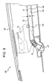
- At least one guide rail and / or a backdrop formed guideway 12 is in its front, in Figures 8 and 9 left Angled forwardly and downwards so that between a front, essentially rectilinearly inclined, parallel guideway area 47 and in the vehicle longitudinal direction behind it, essentially straight, horizontally extending, parallel guideway area 48 a curved guideway area 49 is located.
- power flow F takes place from the cover 45 via the support 14 and the support pin 13 to the relatively fixed support member 15.
- Gleitbacken stresses 20 will reduce the surface pressure between the Sliding cap 26 and the sliding partner, that is, the guideway 12 forming Guide rail or backdrop reached.
- the difference of the widths W 'and W is preferably chosen so that the Sliding jaws 11 when passing through the series of guide track areas 47, 48, 49th only moved and rotated, but not deformed, provided the sliding block 11 and the guideway 12 have their nominal dimensions. In curve areas comes It then to a "three-line support" of the sliding surfaces 34, 35 of the sliding block 11th on the sliding surfaces 41, 42 of the guideway 12. The deformability of Sliding jaw 11 can then be fully necessary for one possibly expectant tolerance compensation be used.
- the described Gleitbacken adjustment allows the wearing of high lid weights.
- the sliding jaw is low-wear over the life of the system, and it reliably ensures a rattle of the system.
Landscapes
- Engineering & Computer Science (AREA)
- Mechanical Engineering (AREA)
- Bearings For Parts Moving Linearly (AREA)
- Fittings On The Vehicle Exterior For Carrying Loads, And Devices For Holding Or Mounting Articles (AREA)
- Platform Screen Doors And Railroad Systems (AREA)
- Lift-Guide Devices, And Elevator Ropes And Cables (AREA)
- Steering Controls (AREA)
- Braking Arrangements (AREA)
- Power-Operated Mechanisms For Wings (AREA)
Abstract
Description
Insbesondere bei großem Gewicht des zu verstellenden Fahrzeugteils, zum Beispiel Deckels, ist dies mit hohem Verschleiß verbunden. Ein solcher Verschleiß führt seinerseits zu ungewolltem Spiel des Gleiters in seinem Führungskanal und damit zum Klappern des Systems bei Unebenheiten der Fahrbahn und dadurch verursachten Stößen auf das Fahrzeug.
Dabei stehen die Gleitflächen 34, 35 des Gleitbackens 11 mit Gleitflächen 41, 42 der Führungsbahn 12 in Gleiteingriff (Fig. 7).
Der Gleitbacken ist über die Lebensdauer des Systems verschleißarm, und er sorgt zuverlässig für eine Klapperfreiheit des Systems.
- 10
- Gleitbackenführung
- 11
- Gleitbacken
- 12
- Führungsbahn
- 13
- Tragbolzen
- 14
- Abstützung
- 15
- Trägerteil
- 16
- Achse von 13
- 17
- Nabe
- 18
- Flügel
- 20
- Gleitbackenkörper
- 21
- Umfangswand
- 22
- Stirnwand
- 23
- Schlitz
- 24
- Schlitz
- 26
- Gleitkappe
- 27
- Umfangswand
- 28
- Stirnwand
- 29
- Rastnase
- 30
- Schulter
- 33
- Längsschlitz
- 34
- Gleitfläche
- 35
- Gleitfläche
- 36
- Abstreifrippen
- 40
- Führungskanal
- 41
- Gleitfläche
- 42
- Gleitfläche
- 45
- Deckel
- 46
- Fahrzeugdach
- 47
- paralleler Führungsbahnbereich
- 48
- paralleler Führungsbahnbereich
- 49
- gebogener Führungsbahnbereich
Claims (20)
- Gleitbackenführung für öffnungsfähige Fahrzeugdächer oder Fahrzeugklappen, mit einer einen Führungskanal (40) aufweisenden Führungsbahn (12) und einem in dem Führungskanal entlang der Führungsbahn verschiebbar geführten Gleitbacken (11), der einen gummielastischen Gleitbackenkörper (20) und eine auf den Gleitbackenkörper aufgesetzte Gleitkappe (26) aufweist, dadurch gekennzeichnet, dass in den gummielastischen Gleitbackenkörper (20) ein Trägerteil (15) eingesetzt ist, das eine höhere Festigkeit und Steifigkeit als der Gleitbackenkörper hat und das seinerseits auf einem Tragbolzen (13) drehbar abgestützt ist.
- Gleitbackenführung nach Anspruch 1, dadurch gekennzeichnet, dass das Trägerteil (15) aus Kunststoff besteht.
- Gleitbackenführung nach Anspruch 2, dadurch gekennzeichnet, dass der Tragbolzen (13) aus Metall gefertigt und mit das Trägerteil (15) bildendem Kunststoff umspritzt ist.
- Gleitbackenführung nach Anspruch 2, dadurch gekennzeichnet, dass das Trägerteil (15) auf den Tragbolzen (13) aufgeclipst ist.
- Gleitbackenführung nach Anspruch 1, dadurch gekennzeichnet, dass das Trägerteil (15) aus Metall besteht und auf den Tragbolzen (13) aufgesteckt ist.
- Gleitbackenführung nach einem der vorhergehenden Ansprüche, dadurch gekennzeichnet, dass das Trägerteil (15) eine den Tragbolzen (13) umgreifende Nabe (17) und zwei von gegenüberliegenden Seiten der Nabe im wesentlichen radial abstehende Flügel (18) aufweist.
- Gleitbackenführung nach einem der vorhergehenden Ansprüche, dadurch gekennzeichnet, dass der Gleitbackenkörper (20) im wesentlichen kappenförmig mit einer Umfangswand (21) und einer an die eine Seite der Umfangswand anschließenden Stirnwand (22) ausgebildet ist.
- Gleitbackenführung nach Anspruch 7, dadurch gekennzeichnet, dass der Gleitbackenkörper (20) im Bereich seiner Umfangswand (21) geschlitzt ist.
- Gleitbackenführung nach einem der vorhergehenden Ansprüche, dadurch gekennzeichnet, dass der Gleitbacken (11) im wesentlichen Quaderform hat.
- Gleitbackenführung nach einem der vorhergehenden Ansprüche, dadurch gekennzeichnet, dass der Gleitbacken (11) sowohl in Längsrichtung als auch in Querrichtung spiegelsymmetrisch ausgebildet ist.
- Gleitbackenführung nach Ansprüchen 8 und 9, dadurch gekennzeichnet, dass die Umfangswand (21) des Gleitbackenkörpers (20) in Längsrichtung des Gleitbackens (11) und/oder in Querrichtung des Gleitbackens geschlitzt ist.
- Gleitbackenführung nach einem der vorhergehenden Ansprüche, dadurch gekennzeichnet, dass die Gleitkappe (26) auf das Trägerteil (15) aufgeclipst ist.
- Gleitbackenführung nach einem der Ansprüche 9 bis 12, dadurch gekennzeichnet, dass die Gleitkappe (26) und das Trägerteil (15) in der Längsrichtung des Gleitbackens (11) im wesentlichen spielfrei miteinander verbunden sind.
- Gleitbackenführung nach Anspruch 13, dadurch gekennzeichnet, dass die Gleitkappe (26) eine Umfangswand (27) aufweist, an deren Innenseite das Trägerteil (15) im Bereich der Schmalseiten des Gleitbackens (11) anliegt.
- Gleitbackenführung nach einem der Ansprüche 9 bis 14, dadurch gekennzeichnet, dass die Gleitkappe (26) mit Bezug auf das Trägerteil (15) sowohl in der Querrichtung des Gleitbackens (11) als auch in Drehrichtung um die Achse (16) des Tragbolzens (13) elastisch verstellbar ist.
- Gleitbackenführung nach Anspruch 15, dadurch gekennzeichnet, dass die Gleitkappe (26) eine Umfangswand (27) aufweist, von deren Innenseite das Trägerteil (15) im Bereich der Längsseiten des Gleitbackens (11) in Abstand liegt.
- Gleitbackenführung nach einem der vorhergehenden Ansprüche, dadurch gekennzeichnet, dass der gummielastische Gleitbackenkörper (20) im wesentlichen den gesamten Raum zwischen dem Trägerteil (15) und der Gleitkappe (26) ausfüllt.
- Gleitbackenführung nach einem der vorhergehenden Ansprüche, dadurch gekennzeichnet, dass in die mit Gleitflächen (41, 42) des Führungskanals (40) in Gleiteingriff kommenden Gleitflächen (34, 35) der Gleitkappe (26) Abstreifrippen (36) integriert sind, die schräg zur Verschieberichtung des Gleitbackens (11) verlaufen.
- Gleitbackenführung nach einem der vorhergehenden Ansprüche, dadurch gekennzeichnet, dass der Führungskanal (40) im Bereich von gebogenen Führungsbahnbereichen (49) der Führungsbahn (12) breiter als im Bereich geradliniger Führungsbahnbereiche (47, 48) ausgebildet ist.
- Gleitbackenführung nach Anspruch 19, dadurch gekennzeichnet, dass die Aufweitung des Führungskanals (40) in gebogenen Führungsbahnbereichen (49) so bemessen ist, dass sich die Gleitbacke (11) an die Gleitflächen (41, 42) des Führungskanals auch beim Durchlaufen solcher gebogener Führungsbahnbereiche im wesentlichen verformungsfrei anschmiegt.
Applications Claiming Priority (2)
| Application Number | Priority Date | Filing Date | Title |
|---|---|---|---|
| DE10237092 | 2002-08-13 | ||
| DE10237092A DE10237092B4 (de) | 2002-08-13 | 2002-08-13 | Gleitbackenführung für öffnungsfähige Fahrzeugdächer oder Fahrzeugklappen |
Publications (2)
| Publication Number | Publication Date |
|---|---|
| EP1389545A1 true EP1389545A1 (de) | 2004-02-18 |
| EP1389545B1 EP1389545B1 (de) | 2009-03-11 |
Family
ID=30469729
Family Applications (1)
| Application Number | Title | Priority Date | Filing Date |
|---|---|---|---|
| EP03018148A Expired - Lifetime EP1389545B1 (de) | 2002-08-13 | 2003-08-08 | Gleitbackenführung für öffnungsfähige Fahrzeugdächer oder Fahrzeugklappen |
Country Status (4)
| Country | Link |
|---|---|
| US (1) | US6799796B2 (de) |
| EP (1) | EP1389545B1 (de) |
| AT (1) | ATE425038T1 (de) |
| DE (2) | DE10237092B4 (de) |
Cited By (4)
| Publication number | Priority date | Publication date | Assignee | Title |
|---|---|---|---|---|
| EP1721770A3 (de) * | 2005-05-11 | 2006-12-13 | ArvinMeritor GmbH | Führungsschiene für ein Kfz-Schiebedachsystem |
| CN101850709A (zh) * | 2009-03-31 | 2010-10-06 | 爱信精机株式会社 | 用于开关构件的支撑机构 |
| FR2982198A1 (fr) * | 2011-11-07 | 2013-05-10 | Peugeot Citroen Automobiles Sa | Dispositif de guidage lineaire de store de vehicule |
| CN108906420A (zh) * | 2017-09-12 | 2018-11-30 | 佛山市南海万发化工塑印包装有限公司 | 一种数控喷雾式薄膜涂布机 |
Families Citing this family (8)
| Publication number | Priority date | Publication date | Assignee | Title |
|---|---|---|---|---|
| DE10329536B4 (de) * | 2003-06-30 | 2007-07-19 | Webasto Ag | Fahrzeugdach |
| EP1634746A1 (de) * | 2004-09-14 | 2006-03-15 | Grupo Antolin-Ingenieria, S.A. | Sonnenschutzvorrichtung mit Lamellen für Kraftfahrzeugdächer |
| DE102007004258B4 (de) * | 2007-01-23 | 2024-12-05 | Webasto SE | Fahrzeugdach mit einem öffnungsfähigen Dachteil |
| DE102009011473B3 (de) * | 2009-03-03 | 2010-11-04 | Webasto Ag | Deckelelementträger mit Stegführung |
| JP6488745B2 (ja) * | 2015-02-10 | 2019-03-27 | アイシン精機株式会社 | サンルーフ装置 |
| JP7310097B2 (ja) * | 2018-04-13 | 2023-07-19 | 株式会社アイシン | サンルーフ装置 |
| US10532639B1 (en) * | 2018-09-06 | 2020-01-14 | AISIN Technical Center of America, Inc. | Holding assembly for a sunroof rail system |
| US10618387B2 (en) * | 2018-09-06 | 2020-04-14 | AISIN Technical Center of America, Inc. | Sunroof rail guide assembly |
Citations (4)
| Publication number | Priority date | Publication date | Assignee | Title |
|---|---|---|---|---|
| US4114945A (en) * | 1975-11-28 | 1978-09-19 | Webasto-Werk W. Baier Gmbh & Co. | Guide shoes |
| EP0403738A2 (de) * | 1989-06-22 | 1990-12-27 | Webasto AG Fahrzeugtechnik | Gleitbacke für Schiebedächer, Schiebehebedächer und dergleichen |
| DE4336222C1 (de) * | 1993-10-23 | 1994-11-24 | Webasto Karosseriesysteme | Gleitschuh für einen Deckel eines öffnungsfähigen Fahrzeugdaches |
| DE10003377A1 (de) * | 2000-01-26 | 2001-08-09 | Webasto Vehicle Sys Int Gmbh | Führungsanordnung für verstellbare Teile an Fahrzeugen |
Family Cites Families (8)
| Publication number | Priority date | Publication date | Assignee | Title |
|---|---|---|---|---|
| JPS607929Y2 (ja) | 1980-10-13 | 1985-03-19 | アイシン精機株式会社 | 自動車用摺動屋根装置 |
| JPH05450Y2 (de) * | 1987-07-31 | 1993-01-07 | ||
| DE3813049A1 (de) * | 1988-04-19 | 1989-11-02 | Webasto Ag Fahrzeugtechnik | Gleitschuh, insbesondere fuer fahrzeugschiebedaecher |
| DE4107129C1 (en) * | 1991-03-06 | 1992-06-04 | Webasto Ag Fahrzeugtechnik, 8035 Stockdorf, De | Guide arrangement for adjustable parts of vehicle roof - has lengthwise groove(s) for sliding jaw coated with solid lubricant |
| FR2693687B1 (fr) * | 1992-07-17 | 1994-09-16 | Heuliez Webasto | Dispositif de coulissement notamment pour toit ouvrant. |
| US5344209A (en) * | 1993-04-02 | 1994-09-06 | Otto Regner | Sunroof assembly |
| DE10033887C1 (de) * | 2000-07-12 | 2001-08-30 | Webasto Vehicle Sys Int Gmbh | Fahrzeugdach mit wenigstens einem oberhalb des festen Fahrzeugdachs verschiebbaren Deckel |
| DE10046129C2 (de) | 2000-09-15 | 2002-10-24 | Webasto Vehicle Sys Int Gmbh | Öffnungsfähiges Fahrzeugdach |
-
2002
- 2002-08-13 DE DE10237092A patent/DE10237092B4/de not_active Expired - Fee Related
-
2003
- 2003-08-08 EP EP03018148A patent/EP1389545B1/de not_active Expired - Lifetime
- 2003-08-08 US US10/636,557 patent/US6799796B2/en not_active Expired - Lifetime
- 2003-08-08 AT AT03018148T patent/ATE425038T1/de not_active IP Right Cessation
- 2003-08-08 DE DE50311265T patent/DE50311265D1/de not_active Expired - Lifetime
Patent Citations (4)
| Publication number | Priority date | Publication date | Assignee | Title |
|---|---|---|---|---|
| US4114945A (en) * | 1975-11-28 | 1978-09-19 | Webasto-Werk W. Baier Gmbh & Co. | Guide shoes |
| EP0403738A2 (de) * | 1989-06-22 | 1990-12-27 | Webasto AG Fahrzeugtechnik | Gleitbacke für Schiebedächer, Schiebehebedächer und dergleichen |
| DE4336222C1 (de) * | 1993-10-23 | 1994-11-24 | Webasto Karosseriesysteme | Gleitschuh für einen Deckel eines öffnungsfähigen Fahrzeugdaches |
| DE10003377A1 (de) * | 2000-01-26 | 2001-08-09 | Webasto Vehicle Sys Int Gmbh | Führungsanordnung für verstellbare Teile an Fahrzeugen |
Cited By (6)
| Publication number | Priority date | Publication date | Assignee | Title |
|---|---|---|---|---|
| EP1721770A3 (de) * | 2005-05-11 | 2006-12-13 | ArvinMeritor GmbH | Führungsschiene für ein Kfz-Schiebedachsystem |
| US7802400B2 (en) | 2005-05-11 | 2010-09-28 | Arvinmeritor Gmbh | Guide rail for a sliding roof system in a motor vehicle |
| CN101850709A (zh) * | 2009-03-31 | 2010-10-06 | 爱信精机株式会社 | 用于开关构件的支撑机构 |
| CN101850709B (zh) * | 2009-03-31 | 2013-08-07 | 爱信精机株式会社 | 用于开关构件的支撑机构 |
| FR2982198A1 (fr) * | 2011-11-07 | 2013-05-10 | Peugeot Citroen Automobiles Sa | Dispositif de guidage lineaire de store de vehicule |
| CN108906420A (zh) * | 2017-09-12 | 2018-11-30 | 佛山市南海万发化工塑印包装有限公司 | 一种数控喷雾式薄膜涂布机 |
Also Published As
| Publication number | Publication date |
|---|---|
| ATE425038T1 (de) | 2009-03-15 |
| US6799796B2 (en) | 2004-10-05 |
| DE10237092B4 (de) | 2004-09-16 |
| EP1389545B1 (de) | 2009-03-11 |
| DE50311265D1 (de) | 2009-04-23 |
| US20040032150A1 (en) | 2004-02-19 |
| DE10237092A1 (de) | 2004-03-04 |
Similar Documents
| Publication | Publication Date | Title |
|---|---|---|
| DE19711487C2 (de) | Dichtungsprofil für Kraftfahrzeuge | |
| EP1389545B1 (de) | Gleitbackenführung für öffnungsfähige Fahrzeugdächer oder Fahrzeugklappen | |
| DE2724414C3 (de) | Einrichtung zum Überführen des Sonnenblendenkörpers einer Sonnenblende für Fahrzeuge von einer Nichtgebrauchslage in eine Gebrauchslage | |
| EP1389546B1 (de) | Gleitbackenführung für öffnungsfähige Fahrzeugdächer oder Fahrzeugklappen | |
| EP1425195B1 (de) | Führungsanordnung für ein dachelement eines öffnungsfähigen fahrzeugdaches | |
| EP1193098A2 (de) | Dichtungssystem für einen Stützhebel an einem öffnungsfähigen Fahrzeugdach | |
| DE102006007978B4 (de) | Teleskopführung mit Rastelement | |
| DE10143374A1 (de) | Vorrichtung zur Aufnahme einer Fahrzeughubeinrichtung | |
| DE10116456A1 (de) | Dachmodul für ein Fahrzeug | |
| DE69705906T2 (de) | Abdichtungsvorrichtung zwischen zwei Elementen und Kraftfahrzeugdach mit einer solchen Abdichtungsvorrichtung | |
| EP2183493A1 (de) | Linearführungssystem | |
| DE10202914B4 (de) | Ausfahrbarer Ladeboden für ein Fahrzeug | |
| DE202012103824U1 (de) | Offendachkonstruktion für ein Fahrzeug | |
| DE4136233C2 (de) | Gleitschuh für ein Schiebedach an einem Fahrzeug | |
| DE102004004909B4 (de) | Dichtungsanordnung | |
| EP0399145A1 (de) | Türfeststeller für Kraftwagentüren | |
| EP0744506A1 (de) | Schwerlastschiebeverschluss | |
| DE102007042882A1 (de) | Führungselement zur Führung zweier relativ zueinander bewegbarer Bauelemente, insbesondere einer Überrollschutzeinrichtung eines Cabriolet-Fahrzeugs | |
| DE10101195B4 (de) | Gleitstück | |
| DE10006832A1 (de) | Betätigungsvorrichtung für eine Feststellbremse | |
| DE19745757A1 (de) | Abdeckleiste | |
| DE202004015512U1 (de) | Fahrzeug | |
| DE4425714C1 (de) | Hebeschiebedach | |
| DE10040064A1 (de) | Haltestange/Gleiter mit Reinigungsnuten | |
| EP1510389A2 (de) | Führungsanordnung für ein verstellbares Element eines Fahrzeugdaches sowie Fahrzeugdach mit einer solchen Führungsanordnung |
Legal Events
| Date | Code | Title | Description |
|---|---|---|---|
| PUAI | Public reference made under article 153(3) epc to a published international application that has entered the european phase |
Free format text: ORIGINAL CODE: 0009012 |
|
| AK | Designated contracting states |
Kind code of ref document: A1 Designated state(s): AT BE BG CH CY CZ DE DK EE ES FI FR GB GR HU IE IT LI LU MC NL PT RO SE SI SK TR |
|
| AX | Request for extension of the european patent |
Extension state: AL LT LV MK |
|
| 17P | Request for examination filed |
Effective date: 20040107 |
|
| AKX | Designation fees paid |
Designated state(s): AT BE BG CH CY CZ DE DK EE ES FI FR GB GR HU IE IT LI LU MC NL PT RO SE SI SK TR |
|
| RAP1 | Party data changed (applicant data changed or rights of an application transferred) |
Owner name: WEBASTO AG |
|
| GRAP | Despatch of communication of intention to grant a patent |
Free format text: ORIGINAL CODE: EPIDOSNIGR1 |
|
| GRAS | Grant fee paid |
Free format text: ORIGINAL CODE: EPIDOSNIGR3 |
|
| GRAA | (expected) grant |
Free format text: ORIGINAL CODE: 0009210 |
|
| AK | Designated contracting states |
Kind code of ref document: B1 Designated state(s): AT BE BG CH CY CZ DE DK EE ES FI FR GB GR HU IE IT LI LU MC NL PT RO SE SI SK TR |
|
| REG | Reference to a national code |
Ref country code: GB Ref legal event code: FG4D Free format text: NOT ENGLISH |
|
| REG | Reference to a national code |
Ref country code: CH Ref legal event code: EP |
|
| REG | Reference to a national code |
Ref country code: IE Ref legal event code: FG4D Free format text: LANGUAGE OF EP DOCUMENT: GERMAN |
|
| REF | Corresponds to: |
Ref document number: 50311265 Country of ref document: DE Date of ref document: 20090423 Kind code of ref document: P |
|
| PG25 | Lapsed in a contracting state [announced via postgrant information from national office to epo] |
Ref country code: SI Free format text: LAPSE BECAUSE OF FAILURE TO SUBMIT A TRANSLATION OF THE DESCRIPTION OR TO PAY THE FEE WITHIN THE PRESCRIBED TIME-LIMIT Effective date: 20090311 Ref country code: FI Free format text: LAPSE BECAUSE OF FAILURE TO SUBMIT A TRANSLATION OF THE DESCRIPTION OR TO PAY THE FEE WITHIN THE PRESCRIBED TIME-LIMIT Effective date: 20090311 |
|
| PG25 | Lapsed in a contracting state [announced via postgrant information from national office to epo] |
Ref country code: SE Free format text: LAPSE BECAUSE OF FAILURE TO SUBMIT A TRANSLATION OF THE DESCRIPTION OR TO PAY THE FEE WITHIN THE PRESCRIBED TIME-LIMIT Effective date: 20090611 |
|
| REG | Reference to a national code |
Ref country code: IE Ref legal event code: FD4D |
|
| PG25 | Lapsed in a contracting state [announced via postgrant information from national office to epo] |
Ref country code: PT Free format text: LAPSE BECAUSE OF FAILURE TO SUBMIT A TRANSLATION OF THE DESCRIPTION OR TO PAY THE FEE WITHIN THE PRESCRIBED TIME-LIMIT Effective date: 20090824 Ref country code: IE Free format text: LAPSE BECAUSE OF FAILURE TO SUBMIT A TRANSLATION OF THE DESCRIPTION OR TO PAY THE FEE WITHIN THE PRESCRIBED TIME-LIMIT Effective date: 20090311 Ref country code: ES Free format text: LAPSE BECAUSE OF FAILURE TO SUBMIT A TRANSLATION OF THE DESCRIPTION OR TO PAY THE FEE WITHIN THE PRESCRIBED TIME-LIMIT Effective date: 20090622 Ref country code: CZ Free format text: LAPSE BECAUSE OF FAILURE TO SUBMIT A TRANSLATION OF THE DESCRIPTION OR TO PAY THE FEE WITHIN THE PRESCRIBED TIME-LIMIT Effective date: 20090311 Ref country code: EE Free format text: LAPSE BECAUSE OF FAILURE TO SUBMIT A TRANSLATION OF THE DESCRIPTION OR TO PAY THE FEE WITHIN THE PRESCRIBED TIME-LIMIT Effective date: 20090311 |
|
| PG25 | Lapsed in a contracting state [announced via postgrant information from national office to epo] |
Ref country code: RO Free format text: LAPSE BECAUSE OF FAILURE TO SUBMIT A TRANSLATION OF THE DESCRIPTION OR TO PAY THE FEE WITHIN THE PRESCRIBED TIME-LIMIT Effective date: 20090311 Ref country code: SK Free format text: LAPSE BECAUSE OF FAILURE TO SUBMIT A TRANSLATION OF THE DESCRIPTION OR TO PAY THE FEE WITHIN THE PRESCRIBED TIME-LIMIT Effective date: 20090311 |
|
| PLBE | No opposition filed within time limit |
Free format text: ORIGINAL CODE: 0009261 |
|
| STAA | Information on the status of an ep patent application or granted ep patent |
Free format text: STATUS: NO OPPOSITION FILED WITHIN TIME LIMIT |
|
| PG25 | Lapsed in a contracting state [announced via postgrant information from national office to epo] |
Ref country code: BG Free format text: LAPSE BECAUSE OF FAILURE TO SUBMIT A TRANSLATION OF THE DESCRIPTION OR TO PAY THE FEE WITHIN THE PRESCRIBED TIME-LIMIT Effective date: 20090611 Ref country code: DK Free format text: LAPSE BECAUSE OF FAILURE TO SUBMIT A TRANSLATION OF THE DESCRIPTION OR TO PAY THE FEE WITHIN THE PRESCRIBED TIME-LIMIT Effective date: 20090311 |
|
| 26N | No opposition filed |
Effective date: 20091214 |
|
| BERE | Be: lapsed |
Owner name: WEBASTO A.G. Effective date: 20090831 |
|
| PG25 | Lapsed in a contracting state [announced via postgrant information from national office to epo] |
Ref country code: MC Free format text: LAPSE BECAUSE OF NON-PAYMENT OF DUE FEES Effective date: 20090831 |
|
| REG | Reference to a national code |
Ref country code: CH Ref legal event code: PL |
|
| PG25 | Lapsed in a contracting state [announced via postgrant information from national office to epo] |
Ref country code: LI Free format text: LAPSE BECAUSE OF NON-PAYMENT OF DUE FEES Effective date: 20090831 Ref country code: CH Free format text: LAPSE BECAUSE OF NON-PAYMENT OF DUE FEES Effective date: 20090831 |
|
| PG25 | Lapsed in a contracting state [announced via postgrant information from national office to epo] |
Ref country code: BE Free format text: LAPSE BECAUSE OF NON-PAYMENT OF DUE FEES Effective date: 20090831 |
|
| PG25 | Lapsed in a contracting state [announced via postgrant information from national office to epo] |
Ref country code: GR Free format text: LAPSE BECAUSE OF FAILURE TO SUBMIT A TRANSLATION OF THE DESCRIPTION OR TO PAY THE FEE WITHIN THE PRESCRIBED TIME-LIMIT Effective date: 20090612 |
|
| PG25 | Lapsed in a contracting state [announced via postgrant information from national office to epo] |
Ref country code: AT Free format text: LAPSE BECAUSE OF NON-PAYMENT OF DUE FEES Effective date: 20090808 |
|
| PG25 | Lapsed in a contracting state [announced via postgrant information from national office to epo] |
Ref country code: IT Free format text: LAPSE BECAUSE OF FAILURE TO SUBMIT A TRANSLATION OF THE DESCRIPTION OR TO PAY THE FEE WITHIN THE PRESCRIBED TIME-LIMIT Effective date: 20090311 |
|
| PG25 | Lapsed in a contracting state [announced via postgrant information from national office to epo] |
Ref country code: LU Free format text: LAPSE BECAUSE OF NON-PAYMENT OF DUE FEES Effective date: 20090808 |
|
| PG25 | Lapsed in a contracting state [announced via postgrant information from national office to epo] |
Ref country code: HU Free format text: LAPSE BECAUSE OF FAILURE TO SUBMIT A TRANSLATION OF THE DESCRIPTION OR TO PAY THE FEE WITHIN THE PRESCRIBED TIME-LIMIT Effective date: 20090912 |
|
| PG25 | Lapsed in a contracting state [announced via postgrant information from national office to epo] |
Ref country code: TR Free format text: LAPSE BECAUSE OF FAILURE TO SUBMIT A TRANSLATION OF THE DESCRIPTION OR TO PAY THE FEE WITHIN THE PRESCRIBED TIME-LIMIT Effective date: 20090311 |
|
| PG25 | Lapsed in a contracting state [announced via postgrant information from national office to epo] |
Ref country code: CY Free format text: LAPSE BECAUSE OF FAILURE TO SUBMIT A TRANSLATION OF THE DESCRIPTION OR TO PAY THE FEE WITHIN THE PRESCRIBED TIME-LIMIT Effective date: 20090311 |
|
| REG | Reference to a national code |
Ref country code: FR Ref legal event code: PLFP Year of fee payment: 14 |
|
| REG | Reference to a national code |
Ref country code: FR Ref legal event code: PLFP Year of fee payment: 15 |
|
| REG | Reference to a national code |
Ref country code: FR Ref legal event code: PLFP Year of fee payment: 16 |
|
| PGFP | Annual fee paid to national office [announced via postgrant information from national office to epo] |
Ref country code: NL Payment date: 20190821 Year of fee payment: 17 |
|
| PGFP | Annual fee paid to national office [announced via postgrant information from national office to epo] |
Ref country code: FR Payment date: 20190822 Year of fee payment: 17 |
|
| PGFP | Annual fee paid to national office [announced via postgrant information from national office to epo] |
Ref country code: GB Payment date: 20190827 Year of fee payment: 17 |
|
| REG | Reference to a national code |
Ref country code: NL Ref legal event code: MM Effective date: 20200901 |
|
| GBPC | Gb: european patent ceased through non-payment of renewal fee |
Effective date: 20200808 |
|
| PG25 | Lapsed in a contracting state [announced via postgrant information from national office to epo] |
Ref country code: FR Free format text: LAPSE BECAUSE OF NON-PAYMENT OF DUE FEES Effective date: 20200831 |
|
| PG25 | Lapsed in a contracting state [announced via postgrant information from national office to epo] |
Ref country code: GB Free format text: LAPSE BECAUSE OF NON-PAYMENT OF DUE FEES Effective date: 20200808 |
|
| PG25 | Lapsed in a contracting state [announced via postgrant information from national office to epo] |
Ref country code: NL Free format text: LAPSE BECAUSE OF NON-PAYMENT OF DUE FEES Effective date: 20200901 |
|
| PGFP | Annual fee paid to national office [announced via postgrant information from national office to epo] |
Ref country code: DE Payment date: 20210819 Year of fee payment: 19 |
|
| REG | Reference to a national code |
Ref country code: DE Ref legal event code: R082 Ref document number: 50311265 Country of ref document: DE Representative=s name: KILIAN KILIAN & PARTNER MBB PATENTANWAELTE, DE |
|
| REG | Reference to a national code |
Ref country code: DE Ref legal event code: R119 Ref document number: 50311265 Country of ref document: DE |
|
| PG25 | Lapsed in a contracting state [announced via postgrant information from national office to epo] |
Ref country code: DE Free format text: LAPSE BECAUSE OF NON-PAYMENT OF DUE FEES Effective date: 20230301 |