EP1388587A1 - Substrat biomoleculaire ainsi que procede et appareil d'examen et de diagnostic mettant en oeuvre celui-ci - Google Patents
Substrat biomoleculaire ainsi que procede et appareil d'examen et de diagnostic mettant en oeuvre celui-ci Download PDFInfo
- Publication number
- EP1388587A1 EP1388587A1 EP02724767A EP02724767A EP1388587A1 EP 1388587 A1 EP1388587 A1 EP 1388587A1 EP 02724767 A EP02724767 A EP 02724767A EP 02724767 A EP02724767 A EP 02724767A EP 1388587 A1 EP1388587 A1 EP 1388587A1
- Authority
- EP
- European Patent Office
- Prior art keywords
- biomolecule
- chip
- signal
- dna
- substrate
- Prior art date
- Legal status (The legal status is an assumption and is not a legal conclusion. Google has not performed a legal analysis and makes no representation as to the accuracy of the status listed.)
- Withdrawn
Links
Images


Classifications
-
- B—PERFORMING OPERATIONS; TRANSPORTING
- B01—PHYSICAL OR CHEMICAL PROCESSES OR APPARATUS IN GENERAL
- B01L—CHEMICAL OR PHYSICAL LABORATORY APPARATUS FOR GENERAL USE
- B01L3/00—Containers or dishes for laboratory use, e.g. laboratory glassware; Droppers
- B01L3/02—Burettes; Pipettes
- B01L3/0241—Drop counters; Drop formers
- B01L3/0244—Drop counters; Drop formers using pins
-
- B—PERFORMING OPERATIONS; TRANSPORTING
- B01—PHYSICAL OR CHEMICAL PROCESSES OR APPARATUS IN GENERAL
- B01J—CHEMICAL OR PHYSICAL PROCESSES, e.g. CATALYSIS OR COLLOID CHEMISTRY; THEIR RELEVANT APPARATUS
- B01J19/00—Chemical, physical or physico-chemical processes in general; Their relevant apparatus
- B01J19/0046—Sequential or parallel reactions, e.g. for the synthesis of polypeptides or polynucleotides; Apparatus and devices for combinatorial chemistry or for making molecular arrays
-
- C—CHEMISTRY; METALLURGY
- C12—BIOCHEMISTRY; BEER; SPIRITS; WINE; VINEGAR; MICROBIOLOGY; ENZYMOLOGY; MUTATION OR GENETIC ENGINEERING
- C12Q—MEASURING OR TESTING PROCESSES INVOLVING ENZYMES, NUCLEIC ACIDS OR MICROORGANISMS; COMPOSITIONS OR TEST PAPERS THEREFOR; PROCESSES OF PREPARING SUCH COMPOSITIONS; CONDITION-RESPONSIVE CONTROL IN MICROBIOLOGICAL OR ENZYMOLOGICAL PROCESSES
- C12Q1/00—Measuring or testing processes involving enzymes, nucleic acids or microorganisms; Compositions therefor; Processes of preparing such compositions
- C12Q1/68—Measuring or testing processes involving enzymes, nucleic acids or microorganisms; Compositions therefor; Processes of preparing such compositions involving nucleic acids
- C12Q1/6813—Hybridisation assays
- C12Q1/6834—Enzymatic or biochemical coupling of nucleic acids to a solid phase
- C12Q1/6837—Enzymatic or biochemical coupling of nucleic acids to a solid phase using probe arrays or probe chips
-
- G—PHYSICS
- G01—MEASURING; TESTING
- G01N—INVESTIGATING OR ANALYSING MATERIALS BY DETERMINING THEIR CHEMICAL OR PHYSICAL PROPERTIES
- G01N33/00—Investigating or analysing materials by specific methods not covered by groups G01N1/00 - G01N31/00
- G01N33/48—Biological material, e.g. blood, urine; Haemocytometers
- G01N33/50—Chemical analysis of biological material, e.g. blood, urine; Testing involving biospecific ligand binding methods; Immunological testing
- G01N33/53—Immunoassay; Biospecific binding assay; Materials therefor
- G01N33/543—Immunoassay; Biospecific binding assay; Materials therefor with an insoluble carrier for immobilising immunochemicals
- G01N33/5436—Immunoassay; Biospecific binding assay; Materials therefor with an insoluble carrier for immobilising immunochemicals with ligand physically entrapped within the solid phase
-
- B—PERFORMING OPERATIONS; TRANSPORTING
- B01—PHYSICAL OR CHEMICAL PROCESSES OR APPARATUS IN GENERAL
- B01J—CHEMICAL OR PHYSICAL PROCESSES, e.g. CATALYSIS OR COLLOID CHEMISTRY; THEIR RELEVANT APPARATUS
- B01J2219/00—Chemical, physical or physico-chemical processes in general; Their relevant apparatus
- B01J2219/00274—Sequential or parallel reactions; Apparatus and devices for combinatorial chemistry or for making arrays; Chemical library technology
- B01J2219/00277—Apparatus
- B01J2219/00351—Means for dispensing and evacuation of reagents
- B01J2219/00378—Piezo-electric or ink jet dispensers
-
- B—PERFORMING OPERATIONS; TRANSPORTING
- B01—PHYSICAL OR CHEMICAL PROCESSES OR APPARATUS IN GENERAL
- B01J—CHEMICAL OR PHYSICAL PROCESSES, e.g. CATALYSIS OR COLLOID CHEMISTRY; THEIR RELEVANT APPARATUS
- B01J2219/00—Chemical, physical or physico-chemical processes in general; Their relevant apparatus
- B01J2219/00274—Sequential or parallel reactions; Apparatus and devices for combinatorial chemistry or for making arrays; Chemical library technology
- B01J2219/00277—Apparatus
- B01J2219/00351—Means for dispensing and evacuation of reagents
- B01J2219/00387—Applications using probes
-
- B—PERFORMING OPERATIONS; TRANSPORTING
- B01—PHYSICAL OR CHEMICAL PROCESSES OR APPARATUS IN GENERAL
- B01J—CHEMICAL OR PHYSICAL PROCESSES, e.g. CATALYSIS OR COLLOID CHEMISTRY; THEIR RELEVANT APPARATUS
- B01J2219/00—Chemical, physical or physico-chemical processes in general; Their relevant apparatus
- B01J2219/00274—Sequential or parallel reactions; Apparatus and devices for combinatorial chemistry or for making arrays; Chemical library technology
- B01J2219/00277—Apparatus
- B01J2219/00495—Means for heating or cooling the reaction vessels
-
- B—PERFORMING OPERATIONS; TRANSPORTING
- B01—PHYSICAL OR CHEMICAL PROCESSES OR APPARATUS IN GENERAL
- B01J—CHEMICAL OR PHYSICAL PROCESSES, e.g. CATALYSIS OR COLLOID CHEMISTRY; THEIR RELEVANT APPARATUS
- B01J2219/00—Chemical, physical or physico-chemical processes in general; Their relevant apparatus
- B01J2219/00274—Sequential or parallel reactions; Apparatus and devices for combinatorial chemistry or for making arrays; Chemical library technology
- B01J2219/00277—Apparatus
- B01J2219/00497—Features relating to the solid phase supports
- B01J2219/00513—Essentially linear supports
- B01J2219/00518—Essentially linear supports in the shape of tapes
-
- B—PERFORMING OPERATIONS; TRANSPORTING
- B01—PHYSICAL OR CHEMICAL PROCESSES OR APPARATUS IN GENERAL
- B01J—CHEMICAL OR PHYSICAL PROCESSES, e.g. CATALYSIS OR COLLOID CHEMISTRY; THEIR RELEVANT APPARATUS
- B01J2219/00—Chemical, physical or physico-chemical processes in general; Their relevant apparatus
- B01J2219/00274—Sequential or parallel reactions; Apparatus and devices for combinatorial chemistry or for making arrays; Chemical library technology
- B01J2219/00277—Apparatus
- B01J2219/00497—Features relating to the solid phase supports
- B01J2219/00527—Sheets
-
- B—PERFORMING OPERATIONS; TRANSPORTING
- B01—PHYSICAL OR CHEMICAL PROCESSES OR APPARATUS IN GENERAL
- B01J—CHEMICAL OR PHYSICAL PROCESSES, e.g. CATALYSIS OR COLLOID CHEMISTRY; THEIR RELEVANT APPARATUS
- B01J2219/00—Chemical, physical or physico-chemical processes in general; Their relevant apparatus
- B01J2219/00274—Sequential or parallel reactions; Apparatus and devices for combinatorial chemistry or for making arrays; Chemical library technology
- B01J2219/00277—Apparatus
- B01J2219/0054—Means for coding or tagging the apparatus or the reagents
- B01J2219/00547—Bar codes
-
- B—PERFORMING OPERATIONS; TRANSPORTING
- B01—PHYSICAL OR CHEMICAL PROCESSES OR APPARATUS IN GENERAL
- B01J—CHEMICAL OR PHYSICAL PROCESSES, e.g. CATALYSIS OR COLLOID CHEMISTRY; THEIR RELEVANT APPARATUS
- B01J2219/00—Chemical, physical or physico-chemical processes in general; Their relevant apparatus
- B01J2219/00274—Sequential or parallel reactions; Apparatus and devices for combinatorial chemistry or for making arrays; Chemical library technology
- B01J2219/00277—Apparatus
- B01J2219/0054—Means for coding or tagging the apparatus or the reagents
- B01J2219/00572—Chemical means
-
- B—PERFORMING OPERATIONS; TRANSPORTING
- B01—PHYSICAL OR CHEMICAL PROCESSES OR APPARATUS IN GENERAL
- B01J—CHEMICAL OR PHYSICAL PROCESSES, e.g. CATALYSIS OR COLLOID CHEMISTRY; THEIR RELEVANT APPARATUS
- B01J2219/00—Chemical, physical or physico-chemical processes in general; Their relevant apparatus
- B01J2219/00274—Sequential or parallel reactions; Apparatus and devices for combinatorial chemistry or for making arrays; Chemical library technology
- B01J2219/00583—Features relative to the processes being carried out
- B01J2219/00585—Parallel processes
-
- B—PERFORMING OPERATIONS; TRANSPORTING
- B01—PHYSICAL OR CHEMICAL PROCESSES OR APPARATUS IN GENERAL
- B01J—CHEMICAL OR PHYSICAL PROCESSES, e.g. CATALYSIS OR COLLOID CHEMISTRY; THEIR RELEVANT APPARATUS
- B01J2219/00—Chemical, physical or physico-chemical processes in general; Their relevant apparatus
- B01J2219/00274—Sequential or parallel reactions; Apparatus and devices for combinatorial chemistry or for making arrays; Chemical library technology
- B01J2219/00583—Features relative to the processes being carried out
- B01J2219/00596—Solid-phase processes
-
- B—PERFORMING OPERATIONS; TRANSPORTING
- B01—PHYSICAL OR CHEMICAL PROCESSES OR APPARATUS IN GENERAL
- B01J—CHEMICAL OR PHYSICAL PROCESSES, e.g. CATALYSIS OR COLLOID CHEMISTRY; THEIR RELEVANT APPARATUS
- B01J2219/00—Chemical, physical or physico-chemical processes in general; Their relevant apparatus
- B01J2219/00274—Sequential or parallel reactions; Apparatus and devices for combinatorial chemistry or for making arrays; Chemical library technology
- B01J2219/00583—Features relative to the processes being carried out
- B01J2219/00603—Making arrays on substantially continuous surfaces
- B01J2219/00605—Making arrays on substantially continuous surfaces the compounds being directly bound or immobilised to solid supports
- B01J2219/0061—The surface being organic
-
- B—PERFORMING OPERATIONS; TRANSPORTING
- B01—PHYSICAL OR CHEMICAL PROCESSES OR APPARATUS IN GENERAL
- B01J—CHEMICAL OR PHYSICAL PROCESSES, e.g. CATALYSIS OR COLLOID CHEMISTRY; THEIR RELEVANT APPARATUS
- B01J2219/00—Chemical, physical or physico-chemical processes in general; Their relevant apparatus
- B01J2219/00274—Sequential or parallel reactions; Apparatus and devices for combinatorial chemistry or for making arrays; Chemical library technology
- B01J2219/00583—Features relative to the processes being carried out
- B01J2219/00603—Making arrays on substantially continuous surfaces
- B01J2219/00605—Making arrays on substantially continuous surfaces the compounds being directly bound or immobilised to solid supports
- B01J2219/00612—Making arrays on substantially continuous surfaces the compounds being directly bound or immobilised to solid supports the surface being inorganic
-
- B—PERFORMING OPERATIONS; TRANSPORTING
- B01—PHYSICAL OR CHEMICAL PROCESSES OR APPARATUS IN GENERAL
- B01J—CHEMICAL OR PHYSICAL PROCESSES, e.g. CATALYSIS OR COLLOID CHEMISTRY; THEIR RELEVANT APPARATUS
- B01J2219/00—Chemical, physical or physico-chemical processes in general; Their relevant apparatus
- B01J2219/00274—Sequential or parallel reactions; Apparatus and devices for combinatorial chemistry or for making arrays; Chemical library technology
- B01J2219/00583—Features relative to the processes being carried out
- B01J2219/00603—Making arrays on substantially continuous surfaces
- B01J2219/00605—Making arrays on substantially continuous surfaces the compounds being directly bound or immobilised to solid supports
- B01J2219/00614—Delimitation of the attachment areas
- B01J2219/00617—Delimitation of the attachment areas by chemical means
-
- B—PERFORMING OPERATIONS; TRANSPORTING
- B01—PHYSICAL OR CHEMICAL PROCESSES OR APPARATUS IN GENERAL
- B01J—CHEMICAL OR PHYSICAL PROCESSES, e.g. CATALYSIS OR COLLOID CHEMISTRY; THEIR RELEVANT APPARATUS
- B01J2219/00—Chemical, physical or physico-chemical processes in general; Their relevant apparatus
- B01J2219/00274—Sequential or parallel reactions; Apparatus and devices for combinatorial chemistry or for making arrays; Chemical library technology
- B01J2219/00583—Features relative to the processes being carried out
- B01J2219/00603—Making arrays on substantially continuous surfaces
- B01J2219/00605—Making arrays on substantially continuous surfaces the compounds being directly bound or immobilised to solid supports
- B01J2219/00614—Delimitation of the attachment areas
- B01J2219/00621—Delimitation of the attachment areas by physical means, e.g. trenches, raised areas
-
- B—PERFORMING OPERATIONS; TRANSPORTING
- B01—PHYSICAL OR CHEMICAL PROCESSES OR APPARATUS IN GENERAL
- B01J—CHEMICAL OR PHYSICAL PROCESSES, e.g. CATALYSIS OR COLLOID CHEMISTRY; THEIR RELEVANT APPARATUS
- B01J2219/00—Chemical, physical or physico-chemical processes in general; Their relevant apparatus
- B01J2219/00274—Sequential or parallel reactions; Apparatus and devices for combinatorial chemistry or for making arrays; Chemical library technology
- B01J2219/00583—Features relative to the processes being carried out
- B01J2219/00603—Making arrays on substantially continuous surfaces
- B01J2219/00605—Making arrays on substantially continuous surfaces the compounds being directly bound or immobilised to solid supports
- B01J2219/00623—Immobilisation or binding
- B01J2219/00626—Covalent
-
- B—PERFORMING OPERATIONS; TRANSPORTING
- B01—PHYSICAL OR CHEMICAL PROCESSES OR APPARATUS IN GENERAL
- B01J—CHEMICAL OR PHYSICAL PROCESSES, e.g. CATALYSIS OR COLLOID CHEMISTRY; THEIR RELEVANT APPARATUS
- B01J2219/00—Chemical, physical or physico-chemical processes in general; Their relevant apparatus
- B01J2219/00274—Sequential or parallel reactions; Apparatus and devices for combinatorial chemistry or for making arrays; Chemical library technology
- B01J2219/00583—Features relative to the processes being carried out
- B01J2219/00603—Making arrays on substantially continuous surfaces
- B01J2219/00605—Making arrays on substantially continuous surfaces the compounds being directly bound or immobilised to solid supports
- B01J2219/00632—Introduction of reactive groups to the surface
- B01J2219/00637—Introduction of reactive groups to the surface by coating it with another layer
-
- B—PERFORMING OPERATIONS; TRANSPORTING
- B01—PHYSICAL OR CHEMICAL PROCESSES OR APPARATUS IN GENERAL
- B01J—CHEMICAL OR PHYSICAL PROCESSES, e.g. CATALYSIS OR COLLOID CHEMISTRY; THEIR RELEVANT APPARATUS
- B01J2219/00—Chemical, physical or physico-chemical processes in general; Their relevant apparatus
- B01J2219/00274—Sequential or parallel reactions; Apparatus and devices for combinatorial chemistry or for making arrays; Chemical library technology
- B01J2219/00583—Features relative to the processes being carried out
- B01J2219/00603—Making arrays on substantially continuous surfaces
- B01J2219/00646—Making arrays on substantially continuous surfaces the compounds being bound to beads immobilised on the solid supports
- B01J2219/00648—Making arrays on substantially continuous surfaces the compounds being bound to beads immobilised on the solid supports by the use of solid beads
-
- B—PERFORMING OPERATIONS; TRANSPORTING
- B01—PHYSICAL OR CHEMICAL PROCESSES OR APPARATUS IN GENERAL
- B01J—CHEMICAL OR PHYSICAL PROCESSES, e.g. CATALYSIS OR COLLOID CHEMISTRY; THEIR RELEVANT APPARATUS
- B01J2219/00—Chemical, physical or physico-chemical processes in general; Their relevant apparatus
- B01J2219/00274—Sequential or parallel reactions; Apparatus and devices for combinatorial chemistry or for making arrays; Chemical library technology
- B01J2219/00583—Features relative to the processes being carried out
- B01J2219/00603—Making arrays on substantially continuous surfaces
- B01J2219/00659—Two-dimensional arrays
-
- B—PERFORMING OPERATIONS; TRANSPORTING
- B01—PHYSICAL OR CHEMICAL PROCESSES OR APPARATUS IN GENERAL
- B01J—CHEMICAL OR PHYSICAL PROCESSES, e.g. CATALYSIS OR COLLOID CHEMISTRY; THEIR RELEVANT APPARATUS
- B01J2219/00—Chemical, physical or physico-chemical processes in general; Their relevant apparatus
- B01J2219/00274—Sequential or parallel reactions; Apparatus and devices for combinatorial chemistry or for making arrays; Chemical library technology
- B01J2219/00583—Features relative to the processes being carried out
- B01J2219/00603—Making arrays on substantially continuous surfaces
- B01J2219/00673—Slice arrays
-
- B—PERFORMING OPERATIONS; TRANSPORTING
- B01—PHYSICAL OR CHEMICAL PROCESSES OR APPARATUS IN GENERAL
- B01J—CHEMICAL OR PHYSICAL PROCESSES, e.g. CATALYSIS OR COLLOID CHEMISTRY; THEIR RELEVANT APPARATUS
- B01J2219/00—Chemical, physical or physico-chemical processes in general; Their relevant apparatus
- B01J2219/00274—Sequential or parallel reactions; Apparatus and devices for combinatorial chemistry or for making arrays; Chemical library technology
- B01J2219/0068—Means for controlling the apparatus of the process
- B01J2219/00686—Automatic
- B01J2219/00689—Automatic using computers
-
- B—PERFORMING OPERATIONS; TRANSPORTING
- B01—PHYSICAL OR CHEMICAL PROCESSES OR APPARATUS IN GENERAL
- B01J—CHEMICAL OR PHYSICAL PROCESSES, e.g. CATALYSIS OR COLLOID CHEMISTRY; THEIR RELEVANT APPARATUS
- B01J2219/00—Chemical, physical or physico-chemical processes in general; Their relevant apparatus
- B01J2219/00274—Sequential or parallel reactions; Apparatus and devices for combinatorial chemistry or for making arrays; Chemical library technology
- B01J2219/0068—Means for controlling the apparatus of the process
- B01J2219/00686—Automatic
- B01J2219/00691—Automatic using robots
-
- B—PERFORMING OPERATIONS; TRANSPORTING
- B01—PHYSICAL OR CHEMICAL PROCESSES OR APPARATUS IN GENERAL
- B01J—CHEMICAL OR PHYSICAL PROCESSES, e.g. CATALYSIS OR COLLOID CHEMISTRY; THEIR RELEVANT APPARATUS
- B01J2219/00—Chemical, physical or physico-chemical processes in general; Their relevant apparatus
- B01J2219/00274—Sequential or parallel reactions; Apparatus and devices for combinatorial chemistry or for making arrays; Chemical library technology
- B01J2219/0068—Means for controlling the apparatus of the process
- B01J2219/00693—Means for quality control
-
- B—PERFORMING OPERATIONS; TRANSPORTING
- B01—PHYSICAL OR CHEMICAL PROCESSES OR APPARATUS IN GENERAL
- B01J—CHEMICAL OR PHYSICAL PROCESSES, e.g. CATALYSIS OR COLLOID CHEMISTRY; THEIR RELEVANT APPARATUS
- B01J2219/00—Chemical, physical or physico-chemical processes in general; Their relevant apparatus
- B01J2219/00274—Sequential or parallel reactions; Apparatus and devices for combinatorial chemistry or for making arrays; Chemical library technology
- B01J2219/0068—Means for controlling the apparatus of the process
- B01J2219/00702—Processes involving means for analysing and characterising the products
-
- B—PERFORMING OPERATIONS; TRANSPORTING
- B01—PHYSICAL OR CHEMICAL PROCESSES OR APPARATUS IN GENERAL
- B01J—CHEMICAL OR PHYSICAL PROCESSES, e.g. CATALYSIS OR COLLOID CHEMISTRY; THEIR RELEVANT APPARATUS
- B01J2219/00—Chemical, physical or physico-chemical processes in general; Their relevant apparatus
- B01J2219/00274—Sequential or parallel reactions; Apparatus and devices for combinatorial chemistry or for making arrays; Chemical library technology
- B01J2219/00718—Type of compounds synthesised
- B01J2219/0072—Organic compounds
- B01J2219/00722—Nucleotides
-
- B—PERFORMING OPERATIONS; TRANSPORTING
- B01—PHYSICAL OR CHEMICAL PROCESSES OR APPARATUS IN GENERAL
- B01L—CHEMICAL OR PHYSICAL LABORATORY APPARATUS FOR GENERAL USE
- B01L2300/00—Additional constructional details
- B01L2300/08—Geometry, shape and general structure
- B01L2300/0832—Geometry, shape and general structure cylindrical, tube shaped
- B01L2300/0841—Drums
-
- B—PERFORMING OPERATIONS; TRANSPORTING
- B01—PHYSICAL OR CHEMICAL PROCESSES OR APPARATUS IN GENERAL
- B01L—CHEMICAL OR PHYSICAL LABORATORY APPARATUS FOR GENERAL USE
- B01L3/00—Containers or dishes for laboratory use, e.g. laboratory glassware; Droppers
- B01L3/02—Burettes; Pipettes
- B01L3/0241—Drop counters; Drop formers
-
- B—PERFORMING OPERATIONS; TRANSPORTING
- B01—PHYSICAL OR CHEMICAL PROCESSES OR APPARATUS IN GENERAL
- B01L—CHEMICAL OR PHYSICAL LABORATORY APPARATUS FOR GENERAL USE
- B01L3/00—Containers or dishes for laboratory use, e.g. laboratory glassware; Droppers
- B01L3/50—Containers for the purpose of retaining a material to be analysed, e.g. test tubes
- B01L3/508—Containers for the purpose of retaining a material to be analysed, e.g. test tubes rigid containers not provided for above
-
- C—CHEMISTRY; METALLURGY
- C40—COMBINATORIAL TECHNOLOGY
- C40B—COMBINATORIAL CHEMISTRY; LIBRARIES, e.g. CHEMICAL LIBRARIES
- C40B40/00—Libraries per se, e.g. arrays, mixtures
- C40B40/04—Libraries containing only organic compounds
- C40B40/06—Libraries containing nucleotides or polynucleotides, or derivatives thereof
-
- C—CHEMISTRY; METALLURGY
- C40—COMBINATORIAL TECHNOLOGY
- C40B—COMBINATORIAL CHEMISTRY; LIBRARIES, e.g. CHEMICAL LIBRARIES
- C40B60/00—Apparatus specially adapted for use in combinatorial chemistry or with libraries
- C40B60/14—Apparatus specially adapted for use in combinatorial chemistry or with libraries for creating libraries
-
- C—CHEMISTRY; METALLURGY
- C40—COMBINATORIAL TECHNOLOGY
- C40B—COMBINATORIAL CHEMISTRY; LIBRARIES, e.g. CHEMICAL LIBRARIES
- C40B70/00—Tags or labels specially adapted for combinatorial chemistry or libraries, e.g. fluorescent tags or bar codes
-
- G—PHYSICS
- G01—MEASURING; TESTING
- G01N—INVESTIGATING OR ANALYSING MATERIALS BY DETERMINING THEIR CHEMICAL OR PHYSICAL PROPERTIES
- G01N35/00—Automatic analysis not limited to methods or materials provided for in any single one of groups G01N1/00 - G01N33/00; Handling materials therefor
- G01N35/00029—Automatic analysis not limited to methods or materials provided for in any single one of groups G01N1/00 - G01N33/00; Handling materials therefor provided with flat sample substrates, e.g. slides
- G01N2035/00099—Characterised by type of test elements
- G01N2035/00158—Elements containing microarrays, i.e. "biochip"
-
- G—PHYSICS
- G01—MEASURING; TESTING
- G01N—INVESTIGATING OR ANALYSING MATERIALS BY DETERMINING THEIR CHEMICAL OR PHYSICAL PROPERTIES
- G01N35/00—Automatic analysis not limited to methods or materials provided for in any single one of groups G01N1/00 - G01N33/00; Handling materials therefor
- G01N35/10—Devices for transferring samples or any liquids to, in, or from, the analysis apparatus, e.g. suction devices, injection devices
- G01N2035/1027—General features of the devices
- G01N2035/1034—Transferring microquantities of liquid
- G01N2035/1037—Using surface tension, e.g. pins or wires
-
- G—PHYSICS
- G01—MEASURING; TESTING
- G01N—INVESTIGATING OR ANALYSING MATERIALS BY DETERMINING THEIR CHEMICAL OR PHYSICAL PROPERTIES
- G01N35/00—Automatic analysis not limited to methods or materials provided for in any single one of groups G01N1/00 - G01N33/00; Handling materials therefor
- G01N35/10—Devices for transferring samples or any liquids to, in, or from, the analysis apparatus, e.g. suction devices, injection devices
- G01N2035/1027—General features of the devices
- G01N2035/1034—Transferring microquantities of liquid
- G01N2035/1041—Ink-jet like dispensers
-
- G—PHYSICS
- G01—MEASURING; TESTING
- G01N—INVESTIGATING OR ANALYSING MATERIALS BY DETERMINING THEIR CHEMICAL OR PHYSICAL PROPERTIES
- G01N35/00—Automatic analysis not limited to methods or materials provided for in any single one of groups G01N1/00 - G01N33/00; Handling materials therefor
- G01N35/10—Devices for transferring samples or any liquids to, in, or from, the analysis apparatus, e.g. suction devices, injection devices
- G01N35/1065—Multiple transfer devices
- G01N35/1074—Multiple transfer devices arranged in a two-dimensional array
Definitions
- the present invention relates to a substrate for use in a test for detecting a biomolecule (e.g., DNA, RNA, a protein, a low-weight organic molecule (ligand, etc.), sugar, lipid, etc.), a biomolecule chip, and a detection apparatus and test (including screening) and diagnosis methods using the same.
- a biomolecule e.g., DNA, RNA, a protein, a low-weight organic molecule (ligand, etc.), sugar, lipid, etc.
- a biomolecule chip e.g., a biomolecule chip, and a detection apparatus and test (including screening) and diagnosis methods using the same.
- a biomolecule chip including a DNA chip, a biochip, a microarray, a protein chip, etc.
- a test method using the same have recently received attention.
- a number of different nucleic acids (DNA such as cDNA and genomic DNA, RNA, PNA, etc.) or peptides are arranged and fixed in spotted pattern on a substrate made of glass or silicon.
- fragments of sample DNA to be tested are hybridized with a labeling substance, such as a fluorophore or an isotope or the like, and capture DNA, or alternatively, a sample polypeptide or ligand to be tested is conjugated with a labeling protein by means of their interaction.
- a detector is used to detect fluorescence from the labeled DNA or the labeling peptide in each spot, or a radiation detector is used to detect radioactivity therefrom, thereby obtaining information on arrangement of labeled DNA or labeling peptide spots. By analyzing this data, genetic information on the sample DNA can be obtained.
- a gene detection method using a DNA chip or the like has the potential to be widely used in the analysis of genes for the diagnosis of a disease or analysis of an organism in the future.
- Examples of a chip application include screening of a compound library for combinatorial chemistry or the like.
- the versatility of the chips also has received attention.
- biomolecule chips require high-precision equipment, leading to high cost for a detection substrate.
- an apparatus for detecting a labeled DNA requires high precision, and therefore, it is difficult for such an apparatus to come into widespread use in small business entities or practitioners.
- Biomolecule chips do not have sufficient ability to process a large amount of data. Therefore, a substrate or a chip capable of processing data in an easy and efficient manner is expected.
- An object of the present invention is to provide a system which can be made even using a poor-precision test apparatus and in which system a test can be performed.
- the present invention provides an apparatus comprising a substrate on which a plurality of biomolecule spots made of a specific type of biomolecule (e.g., DNA, etc.), in which a pattern or arrangement of the spot of the biomolecule (e.g., DNA) is changed depending on specific data so that the data is recorded on the substrate.
- a specific type of biomolecule e.g., DNA, etc.
- the present invention provides the following.
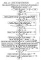
- thepresent invention provides amethod for fabricating a biomolecule substrate, comprising the steps of: 1) providing a set of biomolecules and a substrate; 2) enclosing the set of biomolecules into microcapsules on the biomolecule-type-by-biomolecule-type basis; and 3) spraying the biomolecule microcapsules onto the substrate.
- the present invention further comprises the step of washing the biomolecule microcapsules after the enclosing step.
- the spraying step is performed by an ink jet method.
- the ink j et method is performed by a Bubble Jet® method.
- the present invention further comprises the step of setting the temperature of a solution used in the spraying step to be higher than the melting point of a shell of the biomolecule microcapsulate.
- microcapsules of the set of biomolecules of different types are disposed at different positions.
- the spraying step is performed by a PIN method.
- the biomolecule contains at least one of DNA, RNA and a peptide.
- the biomolecule is DNA.
- the biomolecule is cDNA or genomic DNA.
- the present invention further comprises the step of perform labeling specific to each microcapsule.
- the present invention provides a biomolecule chip, comprising: a substrate; and biomolecules and chip attribute data arranged on the substrate, wherein the chip attribute data is arranged in the same region as that of the biomolecules.
- the chip attribute data contains information relating to chip ID and the substrate.
- the present invention further comprises a recording region, wherein the recording region is placed on the same substrate as that of the biomolecule and the chip attribute data, and at least one of subject data and measurement data is recorded in the recording region.
- the chip attribute data is recorded in such a manner as to be read out by the same means as that for detecting the biomolecule.
- a specific mark is attached to the substrate.
- a specific mark is arranged based on the chip attribute data.
- the chip attribute data contains the biomolecule attribute data.
- information relating to an address of the biomolecule is further recorded.
- the address is a tracking address.
- the chip attribute data is encrypted.
- data relating to a label used to detect the biomolecule is recorded.
- the data relating to the label contains at least one of the wavelength of excited light and the wavelength of fluorescence.
- the biomolecule contains at least one of DNA, RNA and a peptide.
- the biomolecule is DNA.
- the biomolecule is cDNA or genomic DNA.
- the present invention provides a biomolecule chip, comprising: 1) a substrate; and 2) biomolecules arranged on the substrate, wherein spots of the biomolecules are spaced by at least one non-equal interval, an address of the biomolecule spot can be identified from the non-equal interval.
- the non-equal interval is modulated.
- the non-equal interval is present in at least two directions.
- the present invention provides a biomolecule chip.
- This biomolecule chip comprises: 1) a substrate; and 2) biomolecules arranged on the substrate, wherein the biomolecules include a distinguishable first biomolecule and a distinguishable second biomolecule, an address of the biomolecule can be identified based on an arrangement of spots of the first biomolecules and spots of the second biomolecule.
- a label distinguishable from the biomolecule is placed between the biomolecule spots.
- the distinguishable label can be detected by detection means.
- the label is arranged in a horizontal direction and a vertical direction on the substrate.
- a synchronization mark is arranged.
- the biomolecule contains at least one of DNA, RNA and a peptide.
- the biomolecule is DNA.
- the biomolecule is cDNA or genomic DNA.
- the present invention provides a biomolecule chip, comprising: 1) a substrate; and 2) biomolecules arranged on the substrate, wherein spots storing attribute data are arranged on a side of the substrate opposite to a side on which spots of the biomolecules are arranged.
- the attribute data is address information.
- the present invention provides a biomolecule chip, comprising: 1) a substrate; 2) biomolecules arranged on the substrate; and 3) a data recording region.
- the data recording region is placed on the side opposite to the side on which the biomolecules are arranged.
- the present invention provides a method for detecting a label of a biomolecule chip, comprising the steps of: 1) providing a biomolecule chip on which at least one labeled biomolecule is arranged; 2) switching detection elements sequentially for detecting the biomolecules on the biomolecule chip; and 3) identifying a signal detected by the detection element.
- the present invention further comprises: 4) adding up each detected signal.
- the signal is separated by a wavelength separation mirror.
- the biomolecule substrate further contains a synchronization mark, and the label is identified based on the synchronization mark.
- the biomolecule substrate contains address information on a rear side of the biomolecule, and the label is identified based on the address information.
- the present invention provides a method for detecting information on an organism, comprising the steps of: 1) providing a biomolecule sample from the organism; 2) providing the biomolecule chip of the present invention; 3) contacting the biomolecule sample to the biomolecule chip, and placing the biomolecule chip under conditions which causes an interaction between the biomolecule sample and a biomolecule placed on the biomolecule; and 4) detecting a signal caused by the biomolecule and a signal caused by the interaction, wherein the signal is an indicator for at least one information parameter of the organism, and the signal is related to an address assigned to the non-equal interval or the spot arrangement.
- the biomolecule sample contains nucleic acid
- the biomolecule placed on the biomolecule chip is nucleic acid
- the sample contains a protein and the biomolecule placed on the biomolecule chip is an antibody, or the sample contains an antibody and the biomolecule placed on the biomolecule chip is a protein.
- the present invention further comprises labeling the biomolecule sample with a label molecule.
- the label molecule can be distinguished from the biomolecule placed on the biomolecule chip.
- the label molecule contains a fluorescent molecule, a photophorescent molecule, a chemoluminescent molecule, or a radioactive isotope.
- the signal detecting step is performed at a site different from where the interaction occurs.
- the signal detecting step is performed at the same site as where the interaction occurs.
- the present invention further comprises encrypting the signal.
- the present invention further comprises subjecting the signal to filtering so as to extract only signal relating to required information.
- the present invention provides a method for diagnosing a subject, comprising the steps of: 1) providing a sample from the subject; 2) providing the biomolecule chip of the present invention; 3) contacting the biomolecule sample to the biomolecule chip, and placing the biomolecule chip under conditions which cause an interaction between the biomolecule sample and a biomolecule placed on the biomolecule; 4) detecting a signal caused by the biomolecule and a signal caused by the interaction, wherein the signal is at least one diagnostic indicator for the subject, and the signal is related to an address assigned to the non-equal interval or the spot arrangement; and 5) determining the diagnostic indicator from the signal.
- the sample is nucleic acid
- the biomolecule placed on the biomolecule chip is nucleic acid
- the sample contains a protein and the biomolecule placed on the biomolecule chip is an antibody, or the sample contains an antibody and the biomolecule placed on the biomolecule chip is a protein.
- the present invention further comprises labeling the sample with a label molecule.
- the label molecule can be distinguished from the biomolecule placed on the biomolecule chip.
- the label molecule is a fluorescence molecule, a photophorescent molecule, a chemoluminescent molecule, or a radioactive isotope.
- the diagnostic indicator is an indicator for a disease or a disorder.
- the diagnostic indicator is based on single nucleotide polymorphism (SNP).
- the diagnostic indicator is based on a genetic disease.
- the diagnostic indicator is based on the expression level of a protein.
- the diagnostic indicator is based on a test result of a biochemical test.
- the determining step is performed at a site different from where the interaction occurs.
- the signal detecting step is performed at the same site as where the interaction occurs.
- the present invention further comprises encrypting the signal.
- the present invention further comprises subjecting the signal to filtering so as to extract only signal relating to required information.
- biomolecule attribute data is hidden, and in the determining step personal information data is hidden.
- the present invention provides a test apparatus for information on an organism, comprising: 1) the biomolecule chip of the present invention; 2) a sample applying section in fluid communication with the biomolecule chip; 3) a reaction control section for controlling a contact and an interaction between the biomolecule placed on the biomolecule and a biomolecule sample applied from the sample applying section; and 4) a detection section for detecting a signal caused by the interaction, wherein the signal is an indicator for at least one information parameter of the organism, and the signal is related to an address assigned to the non-equal interval or the spot arrangement.
- the present invention further comprises a section for receiving and sending the signal.
- the present invention further comprises a region for recording the signal.
- the present invention provides a diagnosis apparatus for a subject.
- This diagnosis apparatus comprisies: 1) the biomolecule chip of the present invention; 2) a sample applying section in fluid communication with the biomolecule chip; 3) a reaction control section for controlling a contact and an interaction between the biomolecule placed on the biomolecule and a biomolecule sample applied from the sample applying section; 4) a detection section for detecting a signal caused by the biomolecule and a signal caused by the interaction, wherein the signal is an indicator for at least one information parameter of the organism, and the signal is related to an address assigned to the non-equal interval or the spot arrangement; and 5) determining the diagnostic indicator from the signal.
- the present invention further comprises a section for receiving and sending the signal.
- the present invention further comprises a region for recording the signal.
- the present invention provides a biological test system.
- This biological test system comprises: A) a main sub system, comprising: 1) the biomolecule chip of the present invention; 2) a sample applying section in fluid communication with the biomolecule chip; 3) a reaction control section for controlling a contact and an interaction between the biomolecule placed on the biomolecule and a biomolecule sample applied from the sample applying section; 4) a detection section for detecting a signal caused by the biomolecule and a signal caused by the interaction, wherein the signal is an indicator for at least one information parameter of the organism, and the signal is related to an address assigned to the non-equal interval or the spot arrangement; and 5) a sending and receiving section for sending and receiving a signal, and B) a sub sub system, comprising: 1) a sending and receiving section for sending and receiving a signal; and 2) a test section for calculating a test value from the signal received from the main sub system.
- the main sub system and the sub sub system are connected together via a network.
- the signal received by the sub sub system contains a signal relating to measurement data measured by the sub sub system.
- the attribute data contains chip ID, personal information data, and biomolecule attribute data
- the main sub system contains the chip ID and the personal information data, but does not contain the biomolecule attribute data
- the sub sub system contains the chip ID and the biomolecule attribute data, but does not contain the personal information data
- the sub sub system sends the test value, determined in response to a request, to the main sub system.
- the network is the Internet.
- the signal to be sent and received is encrypted.
- the present invention provides a diagnosis system.
- This diagnosis system comprises: A) a main sub system, comprising: 1) the biomolecule chip of the present invention; 2) a sample applying section in fluid communication with the biomolecule chip; 3) a reaction control section for controlling a contact and an interaction between the biomolecule placed on the biomolecule and a biomolecule sample applied from the sample applying section; 4) a detection section for detecting a signal caused by the biomolecule and a signal caused by the interaction, wherein the signal is an indicator for at least one information parameter of the organism, and the signal is related to an address assigned to the non-equal interval or the spot arrangement; and 5) a sending and receiving section for sending and receiving a signal, and B) a sub sub system, comprising: 1) a sending and receiving section for sending and receiving a signal; and 2) a determination section for determining the diagnostic indicator from the signal received from the main sub system.
- the main sub system and the sub sub system are connected together via a network.
- the signal received by the sub sub system contains a signal relating to measurement data measured by the sub sub system.
- the attribute data contains chip ID, personal information data, and biomolecule attribute data
- the main sub system contains the chip ID and the personal information data, but does not contain the biomolecule attribute data
- the sub sub system contains the chip ID and the biomolecule attribute data, and data for determining a diagnostic indicator from biomolecule attribute data, but does not contain the personal information data
- the sub sub system sends the diagnostic indicator, determined in response to a request, to the main sub system.
- the network is the Internet.
- the signal to be sent and received is encrypted.
- the present invention provides a test apparatus for biological information.
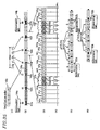
- This test apparatus comprises: a support for a substrate; a plurality of groups of biomolecules arranged on the substrate, each group containining the biomolecules of the same type; shifting means for shifting the substrate; a light source for exciting a fluorescence substance labeling a sample to be tested; and optical means for converging light from the light source.
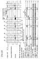
- the light source is caused to emit light intermittently in response to an intermittent emission signal so as to excite the fluorescence substance, fluorescence from the fluorescence substance is detected by a photodetector during a period of time when the intermittent emission signal is paused, identification information is reproduced from an arrangement of the DNAs, and the biomolecules emitting fluorescence is identified.
- the present invention further comprises means for adding up detected detection signals.
- the present invention further comprises a wavelength separation mirror.
- the present invention provides use of the biomolecule chip of the present invention for fabricating an apparatus for testing biological information.
- the present invention provides use of the biomolecule chip of the present invention for fabricating an apparatus for diagnosing a subject.
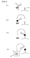
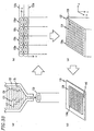
- a schematic diagram showing a method for fixing DNA according to an embodiment of the present invention is shown.
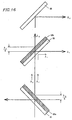
- a timing chart showing detection of fluorescence according to an embodiment of the present invention is shown.
- substrate and “support” as used herein have the same meaning, i.e., a material for an array construction of the present invention (preferably, in a solid form).
- a material for the substrate include any solid material having a property of binding to a biomolecule used in the present invention either by covalent bond or noncovalent bond, or which can be derived in such a manner as to have such a property.
- Such a material for the substrate may be any material capable of forming a solid surface, for example, including, but being not limited to, glass, silica, silicon, ceramics, silica dioxide, plastics, metals (including alloys), naturally-occurring and synthetic polymer (e.g., polystyrene, cellulose, chitosan, dextran, and nylon).
- the substrate may be formed of a plurality of layers made of different materials.
- an inorganic insulating material such as glass, silica glass, alumina, sapphire, forsterite, silicon carbide, silicon oxide, silicon nitride, or the like, can be used.
- an organic material such as polyethylene, ethylene, polypropylene, polyisobutylene, polyethylene terephthalate, unsaturated polyester, fluorine-containing resin, polyvinyl chloride, polyvinylidene chloride, polyvinyl acetate, polyvinyl alcohol, polyvinyl acetal, acrylic resin, polyacrylonitrile, polystyrene, acetal resin, polycarbonate, polyamide, phenol resin, urea resin, epoxy resin, melamine resin, styrene acrylonitrile copolymer, acrylonitrilebutadienestyrene copolymer, silicone resin, polyphenylene oxide, or polysulfone, can be used.
- a film used for nucleic acid blotting such as a nitrocellulose film, a PVDF film, or the like, can also be used.
- an electrode material can be used for a substrate electrode which serves as both a substrate and an electrode.
- a surface of the substrate electrode is separated into electrode regions by an insulating layer region.
- different biomolecules are fixed to the respective isolated electrode regions.
- the electrode material is not particularly limited. Examples of the electrode material include a metal alone, such as gold, gold alloy, silver, platinum, mercury, nickel, palladium, silicon, germanium, gallium, tungsten, and the like, and alloys thereof, or carbon, such as graphite, glassy carbon, and the like, or oxides or compounds thereof.
- a semiconductor compound such as silicon oxide and the like, or various semiconductor devices, such as CCD, FET, CMOS, and the like, can be used.
- the electrode film can be produced by plating, printing, sputtering, depositionor the like.
- an electrode film can be formed by a resistance heating method, a high-frequency heating method, an electron-beam heating method, or the like.
- an electrode film can be produced by direct current sputtering, bias sputtering, asymmetric AC sputtering, getter sputtering, high-frequency sputtering, or the like.
- electropolymerized film such as polypyrrole, polyaniline, and the like, or a conductive polymer can be used.
- An insulating material used for separating the electrode surface in the present invention is not particularly limited, but is preferably a photopolymer or a photoresist material. Examples of the resist material include a photoresist for light exposure, a photoresist for ultraviolet radiation, a photoresist for X ray, and a photoresist for electron beam.
- Examples of a photoresist for light exposure include photoresists including cyclized rubber, polycinnamic acid, and novolac resin as major ingredients.
- photoresists for ultraviolet radiation cyclized rubber, phenol resin, polymethylisopropenylketone (PMIPK), polymethylmethacrylate (PMMA), or the like is used.
- PMIPK polymethylisopropenylketone
- PMMA polymethylmethacrylate
- a photoresist for X ray, COP, methacrylate, or the like can be used.
- As a photoresist for electron beam the above-described substances, such as PMMA or the like, can be used.
- Chip refers to an ultramicro-integrated circuit having various functions, which constitutes a part of a system.
- Biomolecule chip refers to a chip comprising a substrate and a biomolecule, in which at least one biomolecule as set forth herein is disposed on the substrate.
- address refers to a unique position on a substrate which can be distinguished from other unique positions.
- An address is suitably used to access to a biomolecule associated with the address.
- Any entity present at each address can have an arbitrary shape which allows the entity to be distinguished from entities present at other addresses (e.g., in an optical manner).
- the shape of an address may be, for example, a circle, an ellipse, a square, or a rectangle, or alternatively an irregular shape.
- each address varies depending on, particularly, the size of a substrate, the number of addresses on the specific substrate, the amount of samples to be analyzed and/or an available reagent, the size of a biomolecule, and the magnitude of a resolution required for any method in which the array is used.
- the size of an address may range from 1-2 nm to several centimeters (e.g., 1-2 mm to several centimeters, etc., 125 ⁇ 80 mm, 10 ⁇ 10 mm, etc.). Any size of an address is possible as long as it matches the array to which it is applied. In such a case, a substrate material is formed into a size and a shape suitable for a specific production process and application of an array.
- an array may be more economically constructed on a relatively large substrate (e.g., 1 cm ⁇ 1 cm or more).
- a detection system which does not require sensitivity much and is therefore economical may be further advantageously used.
- an array may be designed so that consumption of the sample and reagent is minimized.
- Array refers to a pattern of solid substances fixed on a solidphase surface or a film, or a group of molecules having such a pattern.
- an array comprises biomolecules (e.g., DNA, RNA, protein-RNA fusion molecules, proteins, low-weight organic molecules, etc.) conjugated to nucleic acid sequences fixed on a solid phase surface or a film as if the biomolecule captured the nucleic sequence.
- biomolecules e.g., DNA, RNA, protein-RNA fusion molecules, proteins, low-weight organic molecules, etc.
- spots of biomolecules may be arranged on an array.
- spot refers to a predetermined set of biomolecules.
- any number of addresses maybe arranged on a substrate, typically up to 10 8 addresses, in other embodiments up to 10 7 addresses, up to 10 6 addresses, up to 10 5 addresses, up to 10 4 addresses, up to 10 3 addresses, or up to 10 2 addresses. Therefore, when one biomolecule is placed on one address, up to 10 8 biomolecules can be placed on a substrate, and in other embodiment up to 10 7 biomolecules, up to 10 6 biomolecules, up to 10 5 biomolecules, up to 10 4 biomolecules, up to 10 3 biomolecules, or up to 10 2 biomolecules can be placed on a substrate. In these cases, a smaller size of substrate and a smaller size of address are suitable.
- the size of an address may be as small as the size of a single biomolecule (i.e., this size may be of the order of 1-2 nm).
- the minimum area of a substrate is determined based on the number of addresses on the substrate.
- biomolecule refers to a molecule related to an organism.
- An "organism” as used herein refers to a biological organic body, including, but being limited to, an animal, a plant, a fungus, a virus, and the like.
- a biomolecule includes a molecule extracted from an organism, but is not so limited.
- a biomolecule is any molecule capable of having an influence on an organism. Therefore, a biomolecule also includes amolecule synthesized by combinatorial chemistry, and a low weight molecule capable of being used as a medicament (e.g., a low molecular weight ligand, etc.) as long as they are intended to have an influence on an organism.
- biomolecule examples include, but are not limited to, proteins, polypeptides, oligopeptides, peptides, polynucleotides, oligonucleotides, nucleotides, nucleic acids (e.g., including DNA (such as cDNA and genomic DNA) and RNA (such as mRNA)), polysaccharides, oligosaccharides, lipids, low weight molecules (e.g., hormones, ligands, signal transduction substances, low-weight organic molecules, etc.), and complex molecules thereof, and the like.
- a biomolecule also includes a cell itself, and a part or the whole of tissue, and the like as long as they can be coupled to a substrate of the present invention.
- a biomolecule includes a nucleic acid or a protein.
- a biomolecule isanucleicacid (e.g., genomicDNAorcDNA, orDNAsynthesized by PCR or the like).
- a biomolecule may be a protein.
- one type of biomolecule may be provided for each address on a substrate of the present invention.
- a sample containing two or more types of biomolecules may be provided for each address.
- protein protein
- polypeptide oligopeptide
- peptide as used herein have the same meaning and refer to an amino acid polymer having any length.
- This polymer may be a straight, branched or cyclic chain.
- An amino acid may be a naturally-occurring or non-naturally-occurring amino acid, or a variant amino acid.
- the term may be assembled into a complex of a plurality of polypeptide chains.
- the term also includes a naturally-occurring or artificially modified amino acid polymer. Such modification includes, for example, disulfide bond formation, glycosylation, lipidation, acetylation, phosphorylation, or any other manipulation or modification (e.g., conjugation with a labeling component).
- This definition encompasses a polypeptide containing at least one amino acid analog (e.g., non-naturally-occurring amino acid, etc.), a peptide-like compound (e.g., peptoid), and other variants known in the art, for example.
- amino acid analog e.g., non-naturally-occurring amino acid, etc.
- peptide-like compound e.g., peptoid
- polynucleotide refers to a nucleotide polymer having any length. This term also includes an "oligonucleotide derivative” or a "polynucleotide derivative”.
- An "oligonucleotide derivative” or a “polynucleotide derivative” includes a nucleotide derivative, or refers to an oligonucleotide or a polynucleotide having different linkages between nucleotides fromtypical linkages, which are interchangeably used.
- Examples of such an oligonucleotide specifically include 2'-O-methyl-ribonucleotide, an oligonucleotide derivative in which a phosphodiester bond in an oligonucleotide is converted to a phosphorothioate bond, an oligonucleotide derivative in which a phosphodiester bond in an oligonucleotide is converted to a N3'-P5' phosphoroamidate bond, an oligonucleotide derivative in which a ribose and a phosphodiester bond in an oligonucleotide are converted to a peptide-nucleic acid bond, an oligonucleotide derivative in which uracil in an oligonucleotide is substituted with C-5 propynyl uracil, an oligonucleotide derivative in which uracil in an oligonucleotide is substituted with C-5 thiazole ura
- Gene refers to a factor defining a genetic trait.
- a gene is typically arranged in a certain sequence on a chromosome.
- a gene which defines the first-order structure of a protein is called a structural gene.
- a gene which regulates the expression of a structural gene is called a regulatory gene.
- a “gene” as used herein may refer to a "polynucleotide”, an “oligonucleotide” and a “nucleic acid”, and/or a “protein”, a “polypeptide”, an “oligopeptide” and a “peptide”.
- homoology of a gene refers to the magnitude of identity between two or more gene sequences.
- polysaccharide refers to a polymer compound in which monosaccharides are dehydrocondensed by glycoside bonds.
- Simple sugar or “monosaccharide” refers to a substance represented by the general formula C n H 2n O n , which cannot be decomposed by hydrolysis to a simpler molecule.
- Monosaccharide generally corresponds to an aldehyde or ketone of chain polyhydric alcohol, the former being called aldose and the latter being called ketose.
- a biomolecule of the present invention may be collected from an organism or may be chemically synthesized by a method known to those skilled in the art.
- a synthesis method using an automated solid phase peptide synthesizer is described in the following: Stewart, J. M. et al. (1984). Solid Phase Peptide Synthesis, Pierce Chemical Co. ; Grant, G. A. (1992). Synthetic Peptides: A User's Guide, W. H. Freeman; Bodanszky, M. (1993). Principles of Peptide Synthesis, Springer-Verlag; Bodanszky, M. et al. (1994). The Practice of Peptide Synthesis, Springer-Verlag; Fields, G. B. (1997). Phase Peptide.
- oligonucleotide may be prepared by automated chemical synthesis using any DNA synthesizer commercially available from Applied Biosystems or the like. A composition and a method for automated oligonucleotide synthesis are disclosed in, for example, US Patent No. 4,415,732, Caruthers et al. (1983) ; US Patent No. 4,500,707, Caruthers (1985) ; andUS PatentNo. 4, 668, 777, Caruthers et al. (1987).
- a library of biomolecules may be coupled to a substrate, and a resultant substrate can be used to produce a microarray for screening of molecules.
- a compound library used in the present invention can be prepared or obtained by any means including, but not limited to, a combinatorial chemistry technique, a fermentation method, extraction procedures from plants and cells, or the like.
- a method for producing a combinatorial library is well known in the art. See, for example, E. R. Felder, Chimia 1994, 48, 512-541; Gallopetal., J.Med. Chem. 1994, 37, 1233-1251; R. A. Houghten, Trends Genet.
- “Stringent conditions” as used herein refers to widely used and well known conditions in the art concerning hybridization. Such conditions are, for example, the following: hybridization is conducted in the presence of 0.7 to 1.0 M NaCl at 65°C, and thereafter, 0.1 to 2-fold concentration SSC (saline-sodium citrate) solution (1-fold concentration SSC solution has a composition of 150 mM sodium Chloride, 15 mM sodium citrate) is used to wash a filter at 65°C.
- SSC saline-sodium citrate
- Hybridization can be conducted in accordance with a method described in an experimental manual, such as Molecular Cloning 2nd ed., Current Protocols in Molecular Biology, Supplement 1-38, DNA Cloning 1: Core Techniques, A Practical Approach, Second Edition, Oxford University Press (1995), or the like.
- Comparison in identity between base sequences is herein calculated by a sequence analyzing tool, BLAST, using default parameters.
- a method, biomolecule chip and apparatus of the present invention may be used in, for example, diagnosis, forensic medicine, drug search (medicament screening) and development, molecular biological analysis (e.g., array-base nucleotide sequence analysis and array-base gene sequence analysis), analysis of protein properties and functions, pharmacogenomics, proteomics, environmental assessment, and other biological and chemical analysis.
- molecular biological analysis e.g., array-base nucleotide sequence analysis and array-base gene sequence analysis
- analysis of protein properties and functions e.g., pharmacogenomics, proteomics, environmental assessment, and other biological and chemical analysis.
- a method, biomolecule chip and apparatus of the present invention may be used in the detection of various genes.
- a gene to be detected is not particularly limited. Examples of such a gene to be detected include genes of viral pathogens (including, but not limited to, hepatitis viruses (type A, B, C, D, E, F, and G), HIV, influenza viruses, herpes viruses, adenovirus, human polyoma virus, human Papilloma virus, human Parvovirus, mumps virus, human rotavirus, Enterovirus, Japanese encephalitis virus, dengue virus, rubella virus, and HTLV); genes of bacterial pathogens (including, but not limited to, Staphylococcus aurens , hemolytic streptococcus, virulent Escherichia coli, enteritis vibrio, Helicobacter pylori, Campylobacter, Vibrio cholerae , dysentery bacillus, Salmonella , Yersinia , gunococc
- a method, biomolecule chip and apparatus of the present invention may be used in detection and diagnosis for neoplastic diseases, such as hereditary diseases, retinoblastoma, Wilms' tumor, familial colonic polyposis, neurofibromatosis, familial breast cancer, xeroderma pigmentosum, brain tumor, cancer of the oral cavity, esophageal cancer, stomach cancer, colon cancer, liver cancer, pancreas cancer, lung cancer, thyroid tumor, tumor of the mammary gland, tumor of urinary organs, tumor of male organs, tumor of female organs, skin tumor, tumor of bones and soft parts, leukemia, lymphoma, solid tumor, and the like.
- neoplastic diseases such as hereditary diseases, retinoblastoma, Wilms' tumor, familial colonic polyposis, neurofibromatosis, familial breast cancer, xeroderma pigmentosum, brain tumor, cancer of the oral cavity, esophageal cancer, stomach cancer, colon cancer, liver cancer,
- the present invention can also be applied to polymorphism analysis, such as RFLP analysis, SNP (snipp, single nucleotide polymorphism) analysis, or the like, analysis of base sequences, and the like.
- polymorphism analysis such as RFLP analysis, SNP (snipp, single nucleotide polymorphism) analysis, or the like, analysis of base sequences, and the like.
- the present invention can also be used for screening of a medicament.
- the present invention can be applied to any situation requiring a biomolecule test other than medical applications, such as food testing, quarantine, medicament testing, forensic medicine, agriculture, husbandry, fishery, forestry, and the like.
- the present invention is also intended to be used particularly for the purposes of safety of foods (BSE test).
- the present invention may be used to obtain biochemical test data.
- items of biochemical tests include, but are not limited to, total protein, albumin, thymol reaction, Kunkel's zinc sulfate testing, plasma ammonia, urea nitrogen, creatinine, uric acid, total bilirubin, direct reacting bilirubin, GOT, GPT, cholinesterase, alkaline phosphatase, leucine aminopeptidase, ⁇ -glutamyl transpeptidase, creatinine phosphakinase, lactic dehydrogenase, amylase, sodium, potassium, chloride ion (chlor), total calcium, inorganic phosphor, serum iron, unsaturated iron-binding capability, serum osmotic pressure, total cholesterol, free cholesterol, HDL-cholesterol, triglyceride, phospholipid, free fatty acid, plasma glucose, insulin, BSP retention ratio, ICG disappearance ratio, ICG retention ratio, spinal fluid ⁇ total protein
- the present invention can also be used for detection of a gene amplified by PCR, SDA, NASBA, or the like, other than a sample directly collected from an organism.
- a target gene can be labeled in advance with an electrochemically active substance, a fluorescent substance (e.g., FITC, rhodamine, acridine, Texas Red, fluorecein, etc.), an enzyme (e.g., alkaline phosphatase, peroxidase, glucose oxidase,etc.), acolloidparticle (e.g., a hapten, a light-emitting substance, an antibody, an antigen, gold colloid, etc.), a metal, a metal ion, a metal chelate (e.g., trisbipyridine, trisphenanthroline, hexamine, etc.), or the like.
- a fluorescent substance e.g., FITC, rhodamine, acridine,
- a sample to be tested or diagnosed is not particularly limited and includes, for example, blood, serum, leukocytes, urine, stool, semen, saliva, tissue, cultured cells, sputum, and the like.
- a nucleic acid component is extracted from these samples in order to test nucleic acid.
- the extraction is not limited to a particular method.
- a liquid-liquid extraction method such as phenol-chloroform method and the like, or a liquid-solid extraction method using a carrier can be used.
- a commercially available nucleic acid extraction method QIAamp QIAGEN, Germany
- a sample containing an extracted nucleic acid component is subjected to a hybridization reaction on a biomolecule chip of the present invention. The reaction is conducted in a buffer solution having an ionic strength of 0.01 to 5 and a pH of 5 to 10.
- a hybridization reaction canbe conducted by dropping a solution on a substrate. The rate of a reaction can be increased by stirring or shaking during the reaction. The temperature of a reaction is in the range of 10°C to 90°C. The time of a reaction is in the range of one minute to about one night. After a hybridization reaction, an electrode is removed and then washed. For washing, a buffer solution having an ionic strength of 0.01 to 5 and a pH of 5 to 10 can be used.
- Microcapsule refers to a microparticle enveloping a substance with a molecular membrane or the like, or its container-like substance.
- a microcapsule usually has a spherical shape and a size of several micrometers to several hundred micrometers.
- a microcapsule can be prepared as follows. A water droplet-in-water type emulsion is produced, and a polymer thin film is produced by interfacial polycondensation at an interface between the micro-emulsion particle and a medium so that the particle is covered with the thin film. The capsule is isolated from the oil by centrifugation, followed by dialysis for purification.
- an intended biomolecule is dissolved and dispersed into a water phase, so that the biomolecule can be enveloped in a capsule.
- the thickness of the thin film is 10 to 20 ⁇ m.
- the thin film can be provided with semipermeability or surface charge.
- a microcapsule protects and isolates a content, such as a biomolecule. Such a content can be optionally dissolved, mixed or allowed to react.
- a microcapsule is sprayed onto a substrate by an ink jet method (e.g., Bubble Jet®, etc.), a PINmethod, or the like.
- the sprayedmicrocapsule is heated to a temperature higher than the melting point of its shell so that a content, such as a biomolecule, can be immobilized on the substrate.
- the substrate is preferably coated with a substance having an affinity for the biomolecule.
- Label and “mark” as used herein have the same meaning and refer to an entity which distinguishes an intended molecule or substance from other substances (e.g., a substance, energy, electromagnetic wave, etc.).
- Examples of such a labeling method include anRI (radioisotope) method, a fluorescence method, a biotin method, a chemiluminescence method, and the like.
- fluorescence substance which can bind to a base portion of nucleic acid
- fluorescence substances include cyanine dye (e.g., Cy3, Cy5, etc. in Cy DyeTM series), a rhodamine 6G reagent, N-acetoxy-N2-acetylaminofluorene (AAF), AAIF (an iodine derivative of AAF), and the like.
- Examples of a combination of fluorescence substances having a difference in the maximum wavelength of fluorescence of at least 10 nm include a combination of Cy5 and a rhodamine 6G reagent, a combination of Cy3 and fluorescein, a combination of a rhodamine 6G reagent and fluorescein, and the like.
- Chip attribute data refers to data associated with some information relating to a biomolecule chip of the present invention.
- Chip attribute data includes information associated with a biomolecule chip, such as a chip ID, substrate data, and biomolecule attribute data.
- Chip ID refers to a code for identification of each chip.
- Substrate data or “substrate attribute data” as used herein refers to data relating to a substrate used in a biomolecule chip of the present invention. Substrate data may contain information relating to an arrangement or pattern of a biomolecule.
- Biomolecule attribute data refers to information relating to a biomolecule, including, for example, the gene sequence of the biomolecule (a nucleotide sequence in the case of nucleic acid, and an amino acid sequence in the case of protein), information relating to a gene sequence (e.g., a relationship between the gene and a specific disease or condition), a function in the case of a low weight molecule or a hormone, library information in the case of a combinatorial library, molecular information relating to affinity for a low weight molecule, and the like.
- Perfectal information data refers to data associated with information for identifying an organism or subject to be measured by a method, chip or apparatus of the present invention.
- personal information data includes, but is not limited to, age, sex, health condition, medical history (e.g., drug history), educational background, the company of your insurance, personal genome information, address, name, and the like.
- medical history e.g., drug history
- personal genome information e.g., address, name, and the like.
- personal information data is of a domestic animal, the information may include data about the production company of the animal.
- Measurement data refers to raw data as a result of measurement by a biomolecule substrate, apparatus and system of the present invention and specific processed data derived therefrom. Such raw data may be represented by the intensity of an electric signal.
- processed data may be specific biochemical data, such as a blood sugar level and a gene expression level.
- Recording region refers to a region in which data may be recorded. In a recording region, measurement data as well as the above-described chip attribute data can be recorded.
- personal information data and biomolecule attribute data or measurement data may be separately managed.
- the secrecy of health-related information i.e., personal privacy
- the present invention can be applied to outsourcing in which secret information is protected.
- Micromachining is described in, for example, Campbell, S. A. (1996). The Science and Engineering of Microelectronic Fabrication, Oxford University Press; Zaut, P. V. (1996). Micromicroarray Fabrication: a Practical Guide to Semiconductor Processing, Semiconductor Services; Madou, M. J. (1997). Fundamentals of Microfabrication, CRC1 5 Press; Rai-Choudhury, P. (1997). Handbook of Microlithography, Micromachining, & Microfabrication: Microlithography; and the like, related portions of which are herein incorporated by reference.
- Short Protocols in Molecular Biology A Compendium of Methods from Current Protocols in Molecular Biology, Greene Pub. Associates; Ausubel, F. M. (1995). Short Protocols in Molecular Biology: A Compendium of Methods from Current Protocols in Molecular Biology, Greene Pub. Associates; Innis, M. A. et al. (1995). PCR Strategies, Academic Press; Ausubel, F. M. (1999). Short Protocols in Molecular Biology: A Compendium of Methods from Current Protocols in Molecular Biology, Wiley, and annual updates; Sninsky, J. J. et al. (1999). PCR Applications: Protocols for Functional Genomics, Academic Press; and the like, related portions of which are herein incorporated by reference.
- Nucleic acid chemistry such as DNA synthesis techniques and the like, is described in, for example, Gait, M. J. (1985). Oligonucleotide Synthesis: A Practical Approach, IRL Press; Gait, M. J. (1990). Oligonucleotide Synthesis: A Practical Approach, IRL Press; Eckstein, F. (1991). Oligonucleotides and Analogues: A Practical Approac, IRL Press; Adams, R. L. et al. (1992). The Biochemistry of the Nucleic Acids, Chapman & Hall; Shabarova, Z. et al. (1994). Advanced Organic Chemistry of Nucleic Acids, Weinheim; Blackburn, G. M. et al. (1996). Nucleic Acids in Chemistry and Biology, Oxford University Press; Hermanson, G. T. (I 996). Bioconjugate Techniques, AcademicPress; and the like, related portions of which are herein incorporated by reference.
- Photolithography is a technique developed by Fodor et al., in which a photoreactive protecting group is utilized (see Science, 251, 767(1991)).
- Aprotecting group for a base inhibits a base monomer of the same or different type from binding to that base.
- a protecting group can be easily removed by irradiation. Initially, amino groups having a protecting group are immobilized throughout a substrate. Thereafter, only spots to which a desired base is to be bound are selectively irradiated by a method similar to a photolithography technique usually used in a semiconductor process, so that another base can be introduced by subsequent binding into only the bases in the irradiated portion.
- An ink jet method is a technique of projecting considerably small droplets onto a predetermined position on a two-dimensional plane using heat or a piezoelectric effect. This technique is widely used mainly in printers.
- an ink jet apparatus In production of a DNA array, an ink jet apparatus is used, which has a configuration in which a piezoelectric device is combined with a glass capillary. A voltage is applied to the piezoelectric device which is connected to a liquid chamber, so that the volume of the piezoelectric device is changed and the liquid within the chamber is expelled as a droplet from the capillary connected to the chamber. The size of the expelled droplet is determined by the diameter of the capillary, the volume variation of the piezoelectric device, and the physical property of the liquid.
- the diameter of the droplet is generally 30 ⁇ m.
- An ink jet apparatus using such a piezoelectric device can expel droplets at a frequency of about 10 KHz.
- the ink jet apparatus and a DNA array substrate are relatively moved so that droplets can be dropped onto desired spots on the DNA array.
- DNA array fabricating apparatuses using an ink jet apparatus are roughly divided into two categories. One category includes a DNA array fabricating apparatus using a single ink jet apparatus, and the other includes a DNA array fabricating apparatus using amulti-head ink jet apparatus.
- the DNA array fabricating apparatus with a single ink jet apparatus has a configuration in which a reagent for removing a protecting group at a terminus of an oligomer is dropped onto desired spots.
- a protecting group is removed from a spot, to which a desired base is to be introduced, by using the ink jet apparatus so that the spot is activated.
- the desired base is subjected to a binding reaction throughout a DNA array.
- the desired base is bound to only spots having an oligomer whose terminus is activated by the reagent dropped from the ink jet apparatus.
- the terminus of a newly added base is protected.
- a spot from which a protecting group is removed is changed and the procedures are repeated until desired nucleotide sequences are obtained.
- a DNA array fabricating apparatus using a multi-head ink jet apparatus an ink jet apparatus is provided for each reagent containing a different base, so that a desired base can be bound directly to each spot.
- a DNA array fabricating apparatus using a multi-head ink jet apparatus can have a higher throughput than that of a DNA array fabricating apparatus using a single ink jet apparatus.
- methods for fixing a presynthesized oligonucleotide to a substrate is a mechanical microspotting technique in which liquid containing an oligonucleotide, which is attached to the tip of a stainless pin, is mechanically pressed against a substrate so that the oligonucleotide is immobilized on the substrate.
- the size of a spot obtained by this method is 50 to 300 ⁇ m. After microspotting, subsequent processes, such as immobilization using UV light, are carried out.
- thepresent invention provides amethod for fabricating a biomolecule substrate.
- This method comprises the steps of: 1) providing a set of biomolecules and a substrate; 2) enclosing the set of biomolecules into microcapsules on the biomolecule-type-by-biomolecule-type basis; and 3) spraying the biomolecule microcapsules onto the substrate.
- the set of biomolecules are uniform.
- the method provides a plurality of sets of biomolecules.
- the microcapsules of the set of biomolecules of different types are disposed at different positions.
- the present invention may further comprise the step of washing the biomolecule microcapsules after the enclosing step.
- the spraying step used in the method of the present invention is performed by an ink jet method (including a Bubble Jet® method), a PIN method, or the like.
- the spraying step may be performed by a Bubble Jet® method. This is because the microcapsules may be efficiently immobilized.
- the method may further comprise the step of setting the temperature of a solution used in the spraying step to be higher than the melting point of a shell of the biomolecule microcapsulate. Such an increased temperature of the solution can lead to efficient immobilization of the biomolecules.
- the biomolecule may be a naturally-occurring or synthetic biomolecule.
- a biomolecule include, but are not limited to, a protein, apolypeptide, anoligopeptide, a peptide, a polynucleotide, an oligonucleotide, a nucleotide, nucleic acid (e.g., including DNA, such as cDNA or genomic DNA, and RNA, such as mRNA), a polysaccharide, an oligosaccharide, lipid, a löw weight molecule (e.g., a hormone, a ligand, a signal transduction substance, a low-weight organic molecule, etc.), and composite molecules thereof.
- the biomolecule substrate fabrication method of the present invention may further comprise the step of perform labeling specific to each microcapsule.
- the present invention provides a biomolecule chip.
- This biomolecule chip comprises: a substrate; and biomolecules and chip attribute data arranged on the substrate.
- the chip attribute data is arranged in the same region as that of the biomolecules.
- the above-described chip attribute data may contain information relating to chip ID and the substrate.
- the biomolecule chip of the present invention may further comprise a recording region, wherein the recording region is placed on the same substrate as that of the biomolecule and the chip attribute data, and at least one of the subject data and measurement data is recorded in the recording region.
- both the subject data and measurement data may be recorded in the above-described recording region. Note that when it is intended to protect privacy depending on the purpose, only a part of these pieces of information may be recorded in the recording region. In this case, such data may be encrypted and then recorded.
- the above-described chip attribute data may be recorded in such a manner that the data can be read out by the same means as that for detecting the above-described biomolecule.
- detection means include, but are not limited to, any means capable of detecting the biomolecule, such as a fluorescence analysis apparatus, a spectrophotometer, a scintillation counter, and a luminometer. Since both the chip attribute data and the biomolecule can be read out by the same detection means, both testing of raw data and reading of measurement conditions can be performed by a single read-out operation, thereby making it possible to significantly reduce an operation time and simplifying signal sending and receiving equipment.
- a specific mark may be attached to the above-described substrate. By attaching the specific mark to the substrate, identification of the substrate can be double-checked, thereby making it possible to reduce diagnosis and testing errors.
- the specific mark is arranged based on the chip attribute data. By providing such a specific mark, it is possible to easily read out chip attribute data.
- the above-described chip attribute data may contain the above-described biomolecule attribute data.
- biomolecule attribute data By adding the biomolecule attribute data to the biomolecule chip, various tests and diagnoses can be performed by using only the chip.
- this chip attribute data can be maintained in another site. By maintaining the data in another site, personal information can be prevented from being unintentionally leaked even when the biomolecule chip is unintentionally passed to a third party.
- information relating to an address of the above-described biomolecule may be further recorded.
- address information include geometric information of an arrangement or a pattern defined in the present invention.
- a stand-alone test can be performed.
- the address-related information can also be maintained in another site. By maintaining the information in another site, personal information can be prevented from being unintentionally leaked even when the biomolecule chip is unintentionally passed to a third party.
- the address may be a tracking address.
- the above-described chip attribute data may be encrypted.
- the whole or a part of the data may be encrypted.
- personal information data, biomolecule attribute data, and measurement data may be encrypted.
- These data may be encrypted by separate encryption means.
- Such an encryption means is well known in the art, including, for example, a means using a public key. The present invention is not so limited.
- data relating to a label used to detect the biomolecule may be recorded.
- a label include, but are not limited to, any substance for labeling a biomolecule, such as, for example, a fluorescent molecule, a chemoluminescent molecule, a radioactive isotope, and the like.
- a test or diagnosis can be performed by using only a biomolecule chip.
- the label-related data contains at least one of the wavelength of excited light and the wavelength of fluorescence, and more preferably both of them.
- the biomolecule used in the biomolecule chip of the present invention may be a naturally-occurring or synthetic biomolecule.
- a biomolecule include, but are not limited to, a protein, a polypeptide, an oligopeptide, apeptide, apolynucleotide, anoligonucleotide, anucleotide, nucleic acid (e.g., including DNA, such as cDNA or genomic DNA, and RNA, such as mRNA), a polysaccharide, an oligosaccharide, lipid, a low weight molecule (e.g., a hormone, a ligand, a signal transduction substance, a low-weight organic molecule, etc.), and composite molecules thereof.
- the biomolecule may be a nucleic acid or a protein, and more preferably DNA (e.g., cDNA or genomic DNA).
- the biomolecule may be DNA amplified by an amplification means, such as PCR or the like.
- the biomolecule may be a synthesized protein.
- the present invention provides a biomolecule chip comprising: 1) a substrate; and 2) biomolecules arranged on the substrate, wherein spots of the biomolecules are spaced by at least one non-equal interval, an address of the biomolecule spot can be identified from the non-equal interval.
- the interval can be used as a reference to identify the relative positions of other spots.
- biomolecules are spaced at equal intervals as indicated by 302, except that at least one interval between biomolecules is a non-equal interval as indicated by 303.
- this non-equal interval is used as a starting point, the address of any spot can be identified.
- the non-equal interval is modulated.
- Modulation as used herein refers to variations in spot interval. Modification may be either regular or irregular. An example of such modulation is a sequence of 00, 01, 10, 00, 01, 01, 01 in the binary number system. The present invention is not so limited. By changing modulation, more efficient address identification can be made possible.
- the above-described non-equal intervals may be present in at least two directions.
- the non-equal intervals in the two directions may be distinguished from each other.
- address can be reliably identified even if data is read out in the case when the substrate is turned upside down.
- a plurality of such non-equal intervals may be present.
- such non-equal intervals can be scattered on a substrate.
- the present invention provides a biomolecule chip comprising: 1) a substrate; and 2) biomolecules arranged on the substrate, wherein the biomolecules include a distinguishable first biomolecule and a distinguishable second biomolecule, an address of the biomolecule can be identified based on an arrangement of spots of the first biomolecules and spots of the second biomolecule.
- an address identifying method is also called address identification using a specific "pattern”.
- Figure 48 shows an example of address identification using a specific pattern.
- a first biomolecule 311 can be distinguished from a second biomolecule 312 .
- the address of any spot can be identified.
- Disposinguishable indicates that identification can be carried out by at least one detection means (including, not limited to, the naked eye, a fluorescence measurement apparatus, a spectrophotometer, a radiation measurement apparatus, etc.). Therefore, a distinguishable biomolecule may be, for example, a molecule which can be identified by the naked eye, or a molecule which emits different fluorescence when it is excited. "Distinguishable” also indicates that identification can be carried out by the same label having a different level (e.g., a difference in the amount of dye, etc.).
- a label distinguishable from the biomolecule may be placed between the biomolecule spots.
- a label may be any label as defined herein, and preferably a label which can be detected by the same detection means as the above-described means for detecting a biomolecule.
- the above-described distinguishable label can be detected by a detection means.
- detection means include, but are not limited to, any means capable of detecting the biomolecule, such as a fluorescence analysis apparatus, a spectrophotometer, a scintillation counter, and a luminometer.
- the label may be arranged in a horizontal direction and a vertical direction on the substrate.
- a synchronization mark may be arranged. By providing a synchronization mark, address identification is made easier.
- a biomolecule used in one embodiment of the biomolecule chip of the present invention in which an address is identified by a specific arrangement or a specific pattern may be a naturally-occurring or synthetic biomolecule.
- a biomolecule include, but are not limited to, a protein, a polypeptide, an oligopeptide, a peptide, a polynucleotide, an oligonucleotide, a nucleotide, nucleic acid (e.g., including DNA, such as cDNA or genomic DNA, and RNA, such as mRNA), a polysaccharide, an oligosaccharide, lipid, a low weight molecule (e.g., a hormone, a ligand, a signal transduction substance, a low-weight organic molecule, etc.), and composite molecules thereof.
- the biomolecule maybe a nucleic acid or a protein, and more preferably DNA (e.g., cDNA or genomic DNA).
- the biomolecule may be DNA amplified by an amplification means, such as PCR or the like.
- the present invention provides a biomolecule chip.
- This biomolecule chip comprises: 1) a substrate; and 2) biomolecules arranged on the substrate, wherein spots storing attribute data are arranged on a side of the substrate opposite to a side on which spots of the biomolecules are arranged.
- spots storing attribute data are arranged on a side of the substrate opposite to a side on which spots of the biomolecules are arranged.
- this attribute data may contain address information.
- the attribute data may contain biomolecule attribute data and the like.
- the present invention provides a biomolecule chip comprising: 1) a substrate; 2) biomolecules arranged on the substrate; and 3) a data recording region.
- a biomolecule chip comprising: 1) a substrate; 2) biomolecules arranged on the substrate; and 3) a data recording region.
- the data recording region may be placed on a side of the substrate opposite to a side on which spots of the biomolecules are arranged.
- the present invention provides a method for detecting a label of a biomolecule chip.
- This method comprises the steps of: 1) providing a biomolecule chip on which at least one labeled biomolecule is arranged; 2) switching detection elements sequentially for detecting the biomolecules on the biomolecule chip; and 3) identifying a signal detected by the detection element.
- a signal can be detected efficiently and in real time in a biomolecule chip.
- this method further comprise: 4) adding up each detected signal.
- this signal may be separated using a wavelength separation mirror.
- the above-described biomolecule substrate may further comprise a synchronization mark, and the label may be identified based on the synchronization mark. By providing the synchronization mark, an address can be smoothly identified.
- the biomolecule substrate contains address information on a rear side of the biomolecule, and the label is identified based on the address information.
- the present invention provides a method for testing information from an organism.
- This method comprises the steps of: 1) providing a biomolecule sample from the organism; 2) providing a biomolecule chip of the present invention; 3) contacting the biomolecule sample to the biomolecule chip, and placing the biomolecule chip under conditions which causes an interaction between the biomolecule sample and a biomolecule placed on the biomolecule; and 4) detecting a signal caused by the biomolecule and a signal caused by the interaction, wherein the signal is an indicator for at least one information parameter of the organism, and the signal is related to an address assigned to the non-equal interval or the spot arrangement.
- the sample contains a protein and the biomolecule placed on the biomolecule chip is an antibody, or the sample contains an antibody and the biomolecule placed on the biomolecule chip is a protein.
- hybridization between nucleic acids is detected. This hybridization may be performed under various stringency conditions. When SNP is detected, stringent hybridization conditions may be used. When a gene having a relationship but being far with respect to species is searched for, moderate hybridization conditions may be used. Such hybridization conditions can be determined by those skilled in the art from the well-known routine techniques, depending on the situation.
- the sample contains a protein and the biomolecule placed on the biomolecule chip is an antibody, or the sample contains an antibody and the biomolecule placed on the biomolecule chip is a protein.
- an antigen-antibody reaction is detected.
- An antigen-antibody reaction may be detected under various stringency conditions.
- the antibody may be either a monoclonal antibody or polyclonal antibody.
- the antibody may be a monoclonal antibody.
- the antibody may be a chimera antibody, a humanized antibody, or the like.
- the method of the present invention further comprises labeling the biomolecule sample with a label molecule.
- a desired detection means can be used.
- the label molecule may be distinguished from the biomolecule placed on the biomolecule chip.
- a label which can be distinguished from a biomolecule it is easy to detect a spot in which an interaction occurs.
- the label which can be distinguished from a biomolecule refers to a label which can be distinguished from a biomolecule by at least one detection means as described above.
- the above-described label molecule contains a fluorescent molecule, a photophorescent molecule, a chemoluminescent molecule, or a radioactive isotope.
- a detection means corresponding to the type of label molecule may be used.
- the signal detecting step may be performed either at a site different from where the interaction occurs or at the same site as where the interaction occurs.
- the signal may be encrypted.
- Such encryption is well known in the art. For example, encryption using a public key may be used.
- the method may further Comprise subjecting the signal to filtering so as to extract only signals relating to required information. This step may be required for protecting personal information when outsourcing testing.
- the present invention provides a method for diagnosing a subject.
- the method comprises the steps of: 1) providing a sample from the subject; 2) providing a biomolecule chip of the present invention; 3) contacting the biomolecule sample to the biomolecule chip, and placing the biomolecule chip under conditions which causes an interaction between the biomolecule sample and a biomolecule placed on the biomolecule; 4) detecting a signal caused by the biomolecule and a signal caused by the interaction, wherein the signal is at least one diagnostic indicator for the subject, and the signal is related to an address assigned to the non-equal interval or the spot arrangement; and 5) determining the diagnostic indicator from the signal.
- the sample is nucleic acid
- the biomolecule placed on the biomolecule chip is nucleic acid.
- hybridization between nucleic acids is detected. This hybridization may be performed under various stringency conditions. When SNP is detected, stringent hybridization conditions may be used. By placing nucleic acid relating to a specific disease on a biomolecule chip, a singnal caused by hybridization may be an indicator for the specific disease.
- the sample contains a protein and the biomolecule placed on the biomolecule chip is an antibody, or the sample contains an antibody and the biomolecule placed on the biomolecule chip is a protein.
- an antigen-antibody reaction is detected.
- the antigen-antibody reaction may be detected under various stringency conditions.
- a detected signal may be an indicator relating to the specific disease or condition.
- the method further comprises labeling the sample with a label molecule.
- a desired detection means can be used.
- the label molecule may be distinguishable from a biomolecule placed on the above-described biomolecule chip.
- the above-described label molecule may contain a fluorescent molecule, a phosphorescent molecule, a chemoluminescent molecule, or a radioactive isotope.
- a detection means corresponding to the type of the label molecule may be used.
- the diagnostic indicator may be an indicator for a disease or a disorder.
- the diagnostic indicator may be based on single nucleotide polymorphism (SNP). This diagnostic indicator may be related to a genetic disease.
- the diagnostic indicator may be based on the expression level of a protein.
- the diagnostic indicator may be based on a test result of a biochemical test. A plurality of test values based on the biochemical tests may be used.
- the determining step may be performed either at a site different from where the interaction occurs or at the same site as where the interaction occurs.
- the present invention may further comprise encrypting the signal.
- the method may further comprise subjecting the signal to filtering so as to extract only signals relating to required information. This step may be required for avoiding excessive leakage of personal information to protect the personal information when outsourcing testing.
- biomolecule attribute data is hidden, and in the determining step personal information data is hidden.
- the present invention provides a test apparatus information on an organism.
- This apparatus comprises: 1) a biomolecule chip of the present invention; 2) a sample applying section in fluid communication with the biomolecule chip; 3) a reaction control section for controlling a contact and an interaction between the biomolecule placed on the biomolecule and a biomolecule sample applied from the sample applying section; and 4) a detection section for detecting a signal caused by the interaction, wherein the signal is an indicator for at least one information parameter of the organism, and the signal is related to an address assigned to the non-equal interval or the spot arrangement.
- This apparatus can perform testing of biological information without additional address identification.
- the test apparatus of the present invention further comprises a section for receiving and sending the signal.
- a section for receiving and sending the signal By providing the section for receiving and sending the signal, it is possible to send or receive information to or from the outside.
- This sending and receiving section may be connected to a recording apparatus drive, such as a flexible disk drive, an MO drive, a CD-R drive, a DVD-R drive, or a DVD-RAM drive; or a network, such as the Internet or an intranet.
- the test apparatus of the present invention further comprises a region for recording thesignal. Byproviding the recording region, it is possible to store a result of a test. When the test apparatus is used a plurality of times, stored test results can be compared with each other.
- the present invention provides a diagnosis apparatus for a subject.
- the apparatus comprises: 1) a biomolecule chip of the present invention; 2) a sample applying section in fluid communication with the biomolecule chip; 3) a reaction control section for controlling a contact and an interaction between the biomolecule placed on the biomolecule and a biomolecule sample applied from the sample applying section; 4) a detection section for detecting a signal caused by the biomolecule and a signal caused by the interaction, wherein the signal is an indicator for at least one information parameter of the organism, and the signal is related to an address assigned to the non-equal interval or the spot arrangement; and 5) determining the diagnostic indicator from the signal.
- This apparatus can perform testing of subject information without additional address identification.
- the test apparatus of the present invention further comprises a section for receiving and sending the signal.
- a section for receiving and sending the signal By providing the section for receiving and sending the signal, it is possible to send or receive information to or from the outside.
- This sending and receiving section may be connected to a recording apparatus drive, such as a flexible disk drive, an MO drive, a CD-R drive, a DVD-R drive, or a DVD-RAM drive; or a network, such as the Internet or an intranet.
- the test apparatus of the present invention further comprises a region for recording the signal.
- a region for recording the signal By providing the recording region, it is possible to store a result of diagnosis.
- stored diagnosis results can be compared with each other.
- a biological test system comprising: A) a main sub system, comprising: 1) a biomolecule chip of the present invention; 2) a sample applying section in fluid communication with the biomolecule chip; 3) a reaction control section for controlling a contact and an interaction between the biomolecule placed on the biomolecule and a biomolecule sample applied from the sample applying section; 4) a detection section for detecting a signal caused by the biomolecule and a signal caused by the interaction, wherein the signal is an indicator for at least one information parameter of the organism, and the signal is related to an address assigned to the non-equal interval or the spot arrangement; and 5) a sending and receiving section for sending and receiving a signal, and B) a sub sub system, comprising: 1) a sending and receiving section for sending and receiving a signal; and 2) a test section for calculating a test value from the signal received from the main sub system, wherein the main sub system and the sub sub system are connected together via a network.
- the main sub system and the sub sub system are connected together via a network.
- the signal received by the sub sub system contains a signal relating to measurement data measured by the sub sub system.
- the attribute data contains chip ID, personal information data, and biomolecule attribute data
- the main sub system contains the chip ID and the personal information data, but does not contain the biomolecule attribute data
- the sub sub system contains the chip ID and the biomolecule attribute data, but does not contain the personal information data
- the sub sub system sends the test value, determined in response to a request, to the main sub system. Therefore, the biological test system of the present invention prevents leakage of information to a third party. If information is leaked, privacy can be protected in testing an organism.
- the signal to be sent and received is encrypted.
- the above-described network may be the Internet or other networks (e.g., an intranet, etc.).
- the present invention provides a diagnosis system comprising: A) a main sub system, comprising: 1) the biomolecule chip of the present invention; 2) a sample applying section in fluid communication with the biomolecule chip; 3) a reaction control section for controlling a contact and an interaction between the biomolecule placed on the biomolecule and a biomolecule sample applied from the sample applying section; 4) a detection section for detecting a signal caused by the biomolecule and a signal caused by the interaction, wherein the signal is an indicator for at least one information parameter of the organism, and the signal is related to an address assigned to the non-equal interval or the spot arrangement; and 5) a sending and receiving section for sending and receiving a signal, and B) a sub sub system, comprising: 1) a sending and receiving section for sending and receiving a signal; and 2) a determination section for determining the diagnostic indicator fromthe signal received from the main sub system.
- the main sub system and the sub sub system are connected together via a network.
- the signal to be sent and received is encrypted.
- the signal received by the sub sub system contains a signal relating to measurement data measured by the sub sub system.
- the attribute data contains chip ID, personal information data, and biomolecule attribute data
- the main sub system contains the chip ID and the personal information data, but does not contain the biomolecule attribute data
- the sub sub system contains the chip ID and the biomolecule attribute data, and data for determining a diagnostic indicator from biomolecule attribute data, but does not contain the personal information data
- the sub sub system sends the diagnostic indicator, determined in response to a request, to the main sub system. Therefore, the diagnosis system of the present invention prevents leakage of information to a third party. If information is leaked, privacy can be protected in diagnosis.
- the above-described network may be the Internet or other networks (e.g., an intranet, etc.).
- a test apparatus for biological information comprising: a support for a substrate; a plurality of groups of biomolecules arranged on the substrate, each group containing the biomolecules of the same type; shifting means for shifting the substrate; a light source for exciting a fluorescence substance labeling a sample to be tested; and optical means for converging light from the light source.
- the light source is caused to emit light intermittently in response to an intermittent emission signal so as to excite the fluorescence substance, fluorescence from the fluorescence substance is detected by a photodetector during a period of time when the intermittent emission signal is paused, identification information is reproduced from an arrangement of the DNAs, and the biomolecules emitting fluorescence is identified.
- the test apparatus further comprises means for adding up detected detection signals.
- the test apparatus further comprises a wavelength separation mirror.
- the present invention provides use of a biomolecule chip of the present invention for fabricating an apparatus for testing biological information.
- the present invention provides use of a biomolecule chip of the present invention for fabricating an apparatus for diagnosing a subject.
- the present invention provides use of a biomolecule of the present invention for screening for a medicament and fabricating an apparatus for screening for a medicament.
- the present invention also provides a biomolecule chip for medicament screening.
- the present invention also provides a screening apparatus for medicament screening.
- the present invention also provides a method for screening for a medicament using a biomolecule chip of the present invention.
- Figure 1(a) is a top view of DNA spots 2 in which a group of DNA fragments having a specific sequence are fixed on the substrate 1 in the shape of a dot according to the present invention.
- Figure 1(b) is a cross-sectional view thereof.
- the substrate 1 is usually made of glass and may be made of a plastic.
- the shape of the substrate 1 may be a square like a DNA chip, or a circle.
- DNA dots 2 each contain a different capture DNA which is immobilized on the substrate 1 .
- the size of the DNA dot is 100 to 200 ⁇ m in diameter in the case of a microarray, and 10 to 30 ⁇ m in the case of a DNA chip.
- FIG. 2 A method for forming DNA spots will be described with reference to Figures 2 and 3 .
- (1) shows a capture DNA 3 .
- Amethod of preparing capture DNA is omitted. The capture DNA and labeled DNA with a subject label are subjected to hybridization so as to predict the sequence of subject DNA.
- (2) shows a DNA solution 4 containing the capture DNA 3 .
- (3) shows a DNA microcapsule 6 in which the DNA solution 4 is covered with a covering 5 .
- (4) shows a container 11 in which the DNA microcapsule 6 is dispersed in a solution 8 .
- (5) shows a microcapsule 9 in which the DNA microcapsules 6 shown in (4) are collected and enveloped together with the solution 8 with a sub-membrane.
- This microcapsulation makes it possible to select separately two solutions, i.e., the main solution 4 of DNA and the sub-solution 8 of the DNA microcapsule.
- the DNA solution 4 a solution optimal to DNA or a solution required to immobilize the DNA 3 to the substrate 1 can be selected.
- the sub-solution 8 a solution having an optimal viscosity or washing attachability when DNA is arranged on the substrate 1 in a PIN method or an ink jet method can be selected.
- Figure 3 shows a method for arranging 1 st to K th DNA spots on the substrate 1 by a pinning spot method.
- a moving pin 14 is moved so that the DNA microcapsule can be attached to the moving pin 14 from the DNA container 11 ; at (2) and (3) the DNA microcapsule solution is attached to a tip of a pin 13 ; at (4) the moving pin 14 is washed in a washing section 15 , n th DNA is removed, and thereafter, n+1 th DNA is attached to the moving pin 14.
- 1 st to K th DNAs are attached one after another to the pins 13 on a pin drum 16, being spaced at specific intervals.
- the membrane 6 may be made of a material whose vaporization temperature is lower than the vaporization temperature of the main solution and the membrane 6 may be evaporated.
- a surface of the substrate 1 has been subjected to surface treatment so that DNA is easily immobilized on the surface. Therefore, at (4) the capture DNA 3 is immobilized on the substrate 1 as shown in Figure 8. Apart or the whole of the main solution 4 is dried at (5) and washed at (6) , thereby completing the DNA spot 2 .
- arrangement of DNA spots 2a , 2b , and 2c is modulated so as to incorporate positional information thereinto. According to this positional information, the positional orders of the respective DNA spots 2 can be determined.
- a DNA spot region 17 and a data region 18 are separated from each other.
- a substrate ID 19 , a DNA number correspondence table 20 for the position of a DNA spot and a DNA spot ID, and the sequence data 21 of DNA itself (biomolecule attribute data) (data structure shown in Figure 5(2) ) are modulated and recorded in a dot pattern.
- the dot pattern can be read by an XY scanner. Therefore, the arrangement data of DNA spots can be read by an XY scanner.
- DNA substrate ID 19 a DNA number-position correspondence table 20 indicating the correspondence between DNA numbers and positional information
- DNA sequence data 21 indicating the DNA sequence of each DNA
- the DNA sequence data of a DNA number is encrypted using an encryption key and then recorded.
- Personal DNA data is information of a high level of personal privacy which has to be stringently protected, and therefore, is encrypted using a public key, such as RSA, ellipse code, or the like, or a high-bit encryption key.
- DNA sequence data 21 in a DNA management center without recording the data in DNA chips in order to improve security.
- the user informs a DNA management center of a DNA substrate ID 19 and a reaction between labeled DNA 22 and a DNA spot 2, i.e., fluorescence level data.
- the center searches a DNA substrate database for the DNA sequence of each DNA spot using the DNA substrate ID 19 .
- the center further analyzes a reaction result of a DNA spot and labeled DNA 22 , DNA sequence-disease correspondence data to diagnose and predict a disease (in the case of a human), and sends only necessary information to laboratory medical technologist or a doctor in encrypted form. With this system, privacy information is prevented from improperly leaking.
- FIG. 9 is a block diagram showing an ink jet (Bubble Jet®) attaching apparatus.
- An ink jet nozzle 24 contains microcapsules 9a, 9b containing DNA and empty microcapsules 23a, 23b, 23c, 23d containing only main solution 4 , which are supplied from an ink supplying section 25 .
- a specific empty capsule contains a specific dye for indicating address information.
- a master control section 28 sends an eject command to an eject signal generation section 29 and then an eject control circuit 27 . As a result, an eject section 26 generates heat so that bubbles occur.
- the bubbles cause the microcapsule 9a to be ejected toward a substrate.
- the empty microcapsules 23b, 23c are ejected. However, the empty microcapsules 23b, 23c are unnecessary.
- a photodetector 31 detects an empty microcapsule, a removal signal generation section 30 sends a removal signal to an unnecessary liquid removing section 32 .
- a deviation field is applied to a deviation section 33 so that unnecessary liquid in the empty microcapsule 23 is removed as indicated by dashed-line arrow 34 and does not reach a substrate.
- the photodetector 31 has color filters 31g, 31h, 31i (R, G, B, etc.), and therefore, can detect the color information of an empty microcapsule.
- the photodetector 31 also has a counter section 111.
- a first counter 111a counts the number of microcapsule blocks.
- a second counter 111b counts the number of DNA microcapsules.
- Athird counter 111c counts the number of empty microcapsules.
- 2-bit address data is obtained from a set of empty microcapsules.
- 16-bit address data is obtained from 8 empty microcapsules.
- microcapsules Even when microcapsules are not colored, 2 bits can be obtained by ejecting 1, 2, 3, or 4 microcapsules consecutively. When 8 sets are used, 16 bits can be obtained, i.e., the same size of address data as above can be obtained.
- the address information of a microcapsule obtained by the photodetector 31 is sent via an address output section 31p to the master control section.
- DNA number can be identified based on address information. For example, as shown in step 68m in a flowchart of Figure 15 , if a microcapsule makes the number of DNA capsules having DNA number n greater by one, a removal section described below removes the microcapsule.
- the substrate 1 is moved by a predetermined amount by a shift section 37 controlled by a shift amount control circuit 36 based on a signal from a shift amount detector 35 , so that DNA spots 2a to 2h are attached onto the substrate 1 as shown in Figure 10(4) .
- step 68m a result of step 68m is NO, the process goes to step 68p. If the number of microcapsules is smaller by L than the reference value, ejection is stopped for clocks corresponding to L microcapsules in step 68q. During this time, DNA spot 2 is missing. Therefore, a defect block flag is set to be 1, which is recorded in the data region 18 on the DNA substrate 2 , indicating the presence of the defect.
- the address of a microcapsule in an address counter 112 or an address block counter 113 is corrected by increasing the address by L.
- step 68g The number of DNA microcapsules is checked in step 68h. If the result is OK, the eject signal is set to be ON and the removal signal is set to be OFF for one unit in step 68i. In this case, microcapsules are ejected so that one DNA spot is formed. In this case, it is judged that there is no defect, and the address for a DNA microcapsule is increased by one (step 68k). The process then returns to step 68b. Thus, DNA spots 2 , which contain corresponding DNA, can be formed.
- the microcapsule 9a containing n th DNA reaches the tip of the nozzle 24.
- a voltage is applied to the eject section 26 in (2) , a bubble is generated so that the microcapsule 9a is ejected in (3) and is attached to the substrate 1 in (4).
- This method is called Bubble Jet®.
- a piezoelectric device may be provided instead of the eject section 26 to obtain the same effect. In this case, by applying an eject voltage to the piezoelectric device, a microcapsule is ejected in a piezoelectric ink jet method. Meanwhile, the microcapsule 9b containing (n+1) th DNA reaches the tip portion.
- the microcapsule 9b When an eject voltage is applied in (5), the microcapsule 9b is ejected toward the substrate 1 . In (6), (n+2) th microcapsule 9c is transported to the tip portion. In this case, the empty microcapsules 23d, 23e among the three consecutive empty microcapsules 23c, 23d, 23e indicating a synchronization mark are present on the photodetectors 31a, 31b . These empty microcapsules have a high level of transmittance, both of which are detected by the photodetector 31 . The capsules are detected as synchronization marks. Therefore, the microcapsule 9d following these capsules is recognized as containing (n+3) th DNA from a correspondence table.
- a synchronization mark is composed of 2, 3, or 4 empty capsules. One set can contain 2-bit data.
- a synchronization capsule is used to match DNA itself to its DNA number, so that the matched DNA can be ejected. If DNA having a specific number is not ejected as in step 68p of Figure 15 , lack information is recorded in the data region of Figure 5. As shown in Figure 12, for example, a plurality of (n+1) th DNA spots are formed as DNA spots 3a, 3b, 3c. Therefore, a lack of DNA spot does not cause a problem.
- the synchronization capsules 23d , 23e reach the tip portion.
- These capsules do not contain DNA and are unnecessary. Therefore, a removal signal is applied in (8) , the capsules are deviated and removed by the unnecessary liquid removing section 32 so that the capsules do not reach the substrate 1 .
- the removal circuit can prevent unnecessary substances from being attached to the substrate 1 .
- a light detection signal, an eject signal, a removal signal and an arrangement of DNA spots will be described with reference to Figure 10 .
- a system is operated in accordance with a shift clock in Figure 10(3).
- the DNA capsule is detected in synchronization with an eject signal in (4) .
- Synchronization capsules are detected as shown in (2) since the two photodetectors 31a, 31b are both turned ON.
- an eject signal is generated both for a microcapsule containing DNA and a synchronization capsule containing no DNA.
- a removal signal of (5) is generated in synchronization with an eject signal following a detection signal of (2) so that all synchronization capsules are removed.
- positional data such as address or the like
- the positional data is divided into 00, 01, 10, 00, and 01 as shown in (10) , where 00 corresponds to a mark interval of 3 clocks and 01, 10 and 11 corresponds to 4t, 5t and 6t, respectively.
- interval modulation is performed.
- positional information can be buried when DNA spots are formed. Since the address of each DNA spot is obtained, the DNA number of a first DNA spot for a synchronization mark is obtained from DNA number positional information 20 shown in Figure 6 . In the present invention, therefore, the DNA numbers of all DNA spots 2 can be identified.
- the sequence information of all DNA spots can be obtained by using sequence information 21 for DNA numbers recorded in the substrate 1 of Figure 6. Since the address is obtained, absolute precision is not required when the position of a DNA spot is read out. Therefore, a high-precision XY scanner is not required and it is possible to prepare and read a DNA spot with a low-precision apparatus, thereby making it possible to supply an inexpensive DNA testing apparatus.
- Figure 30 shows a sub-nozzle 116 , a sub-eject section 114 , and a sub-solution supply section 115 in addition to the system of Figure 9 .
- the sub-nozzle 116 is supplied with microcapsules, and a sub-solution from the sub-solution supply section 115 .
- Example 3 a fiber convergence type fabrication method is used as an example, a method for burying data (e.g., address, chip ID, and the like) by arrangement of biomolecule spots, which is a feature of the present invention, can be applied to other methods, such as a PIN method, an ink jet method, a semiconductor masking method, and the like.
- a probe 131 corresponding to a specific DNA, RNA and protein is injected together with a gel solution into a hollow thread tube 130 from a container 132 containing the probe 131 in the gel form.
- Different probes 131a, 131b, 131c, 131d, etc. are injected into respective tubes 130a, 130b, 130c, 131c, 130d, etc., which are then bundled in an X direction, i.e., horizontally, to form a sheet 133 as shown in Figure 33(b).
- the bundled sheets 133a, 133b are piled so that the tubes 130 are arranged in a matrix to form a block 137 as shown in Figure 33(c).
- the tubes may be arranged in a circle to form a column-like block.
- a mark tube 134 for a mark indicating an address or data is placed in the block.
- a mark tube 136 is placed in the block, which comprises a probe solution 135 or a tube 130 in which a material for reflecting, absorbing, or emitting fluorescence having a specific wavelength is contained.
- the mark tube 136 will be described in detail below.
- Figure 33(c) shows a 10 ⁇ 10 matrix, the actual matrix has a side of several hundreds to several thousands of tubes.
- the block 137 is sliced in a Z direction, so that a chip 138 is completed.
- the chip 138 is fixed on a fix plate 139 .
- the fix plate 139 is used to fix a chip and may comprise a container for holding a specimen, and is shipped in this form.
- the fix plate 139 is used without modification to perform testing.
- a fix plate ID 140 which varies depending on corresponding attributes of probes, is recorded in the form of a bar code, characters, or a bit pattern.
- a chip ID for managing a process control or the attribute data of a chip is recorded in the first sheet 133a by a method for burying data according to the present invention. This attribute data can be used to identify chips having different probe sequences. Therefore, by checking, it is possible to detect when an incorrect fix plate ID 140 is provided to a chip 138 .
- a spot of each probe is placed on the chip 138 .
- Data is buried in an arrangement of spots.
- a spot containing the probe 131 for detecting DNA or protein is herein referred to as a DNA spot 2 .
- Such a spot may also be called biomolecule spot.
- a method for burying data will be described. Specifically, as shown in Figure 35(3) , for example, 10 biomolecule spots 141e to 141p are aligned in an x direction. Two mark spots 142a, 142b are placed at the left end and three mark spots 142c, 142d, 142e are placed at the right end. Firstly, the case where the mark spots include no biomolecule will be described. The case where the mark spots include a biomolecule(s) will be described later.
- a mark spot has an optical property different from a biomolecule spot 141 in terms of specific wavelength.
- a mark spot has a reflectance or absorbance with respect to a specific wavelength, or the presence or absence of fluorescence or the intensity of fluorescence with respect to a specific wavelength, different from a biomolecule spot. Therefore, a mark spot can be clearly distinguished from the biomolecule spot 141 .
- the mark spot can be optically clearly distinguished from the biomolecule spot as indicated by hatched lines in Figure 35(3) .
- the same effect can also be obtained when the wavelength of fluorescence of the mark spot 142 with respect to excited light is different from the wavelength of fluorescence of the biomolecule spot 141 .
- FIG 35(4) The intensity of reflected light or fluorescence obtained by irradiating the mark spot with light having a specific wavelength is illustrated in Figure 35(4) .
- a group of the mark spots 142 in (3) are collectively called identification mark 143.
- 2-bit codes, "10", "11”, and the like are assigned to respective identification marks 143e, 143f .
- Figure 35(2) shows a general view including the identification marks 143e, 143f where part of biomolecule spots 141 between identification marks are omitted. This figure shows 7 identification marks 143a to 143g , to which codes 00, 10, 11, 01, 10, 11, and 00 are assigned, respectively.
- the five identification marks 143 between the synchronization marks 144 can be used to bury 10-bit data, i.e., 10, 11, 01, 10, and 11.
- the 10-bit data is read from this region. If these 10 bits are used as, for example, address data, the address of this region, "1011011011", can be obtained only by reading the 10 bits.
- a third biomolecule spot 141x to the right of the identification mark 143c is 23 rd biomolecule spot in address "1011011011". Therefore, the identification number 145 of a biomolecule spot can be identified as "101101011-23". Therefore, all biomolecule spots 141 on a chip can be individually identified without counting spots from an end of a matrix.
- a conventional method for identifying a spot by counting spots from an end of a matrix to the x, y coordinates of the matrix corresponding to that spot is made unnecessary.
- the attribute information contained in the attribute table 146 of Figure 40 includes the sequence or genetic information, or marker information of a specific disease, of a biomolecule having this identification number, or DNA, RNA, or other substances hybridizable to this biomolecule probe, and the like.
- the present invention has an advantageous effect that the identification number of a biomolecule 141 can be precisely identified by reading locally the vicinity of the biomolecule 141 even if biomolecule spots are not arranged in a precise matrix.
- Biomolecule chip fabrication methods other than a semiconductor process can be used to fabricate a large number of chips containing biomolecule spots. Even in the case of a perfect matrix arrangement obtained by a semiconductor process, as the number of spots is increased, error occurs in counting spots on a test apparatus, potentially resulting in an incorrect identification number. In the present invention, it is not necessary to count spots with respect to x and y from an end of a biomolecule chip, and therefore, counting error does not occur.
- the identification number of each biomolecule spot can be obtained by reading only the vicinity of the biomolecule spot, whereby the identification number of a desired biomolecule spot can be identified in a short time.
- a specimen with a fluorescent label is provided and hybridized to a surface of a biomolecule chip 138 fabricated by a chip fabrication process, such as a tube method, a semiconductor process method, an ink jet method, a PIN method, or the like. Unhybridized specimens, which are unnecessary, are removed in step 148b.
- This chip is loaded into a laser scanning type test apparatus or a CCD readout type test apparatus shown in Figure 14 described later.
- step 148c chip ID written in the first line of the chip 138 or/and a fix plate ID 140 on the fix plate 139 of Figure 33 is read out by a light beam, CCD, or the like, so as to check the chip ID or the fix plate ID against a predetermined one.
- these IDs are checked against a predetermined ID list. If a result of the above-described check is incorrect, the process is stopped. If the result of the check is correct, an attribute table 146 (see Figure 40 ) corresponding to the chip ID is obtained via a network 150, such as the Internet, LAN, or the like, and is temporarily stored in amemory 151 of a test apparatus 149.
- a network 150 such as the Internet, LAN, or the like
- step 148d m is set to be 0.
- step 148e m is increased by one.
- step 148f a surface of the chip is irradiated with excited light having a first wavelength of ⁇ 1. While scanning the chip using a laser or a CCD, a wavelength separation filter, such as mirrors 65, 66 in Figure 14, is used to search for m th biomolecule spot emitting fluorescence with a specific wavelength. The search is continued until the spot is found in step 148g. When the m th biomolecule spot is found, the chip is irradiated with excited light or reference light in step 148h.
- n is set to be 0.
- n is incremented by 1, the code of n th identification mark 143 is identified.
- This data row contains an error correction code 152 in order to improve the reliability of the data row. Therefore, the data row is subjected to error correction in step 148p, and the data row having no error is obtained in step 148q.
- step 148r by counting the number of spots from an identification mark 143 closest to a subject biomolecule spot, the total number of biomolecule spots from a synchronization mark to the subject biomolecule spot 141 (e.g., 141x ) as shown in Figure 35(2) can be obtained.
- the identification number 145 of the m th biomolecule spot is identified based on the address and the number of counters. In this case, the wavelength of fluorescence can be specified from a filter setting, and therefore, the label number of the fluorescence is identified.
- step 148t the attribute table 146 corresponding to chip ID is read out from the memory 151 , and the sequence data of DNA or the like having a specific identification number is retrieved as shown in Figure 40 . Therefore, the type of DNA, RNA, or a protein contained in a specimen can be obtained.
- this information and the identification number are registered into a test database 147 of the memory 151 .
- step 148v it is checked whether any other biomolecule spots emitting fluorescence remain unread. If there is an unread spot, the process returns to step 148e and the biomolecule spot emitting fluorescence is located. If there is no unread spot, data of test database 147 is sent to an analysis program 155 in step 148x. In step 148y, an analyzed test or diagnosis result is output. Thus, the operation is completed.
- data such as addresses, chip ID, or the like
- the identification number of a biomolecule spot of interest can be obtained from the arrangement of biomolecule spots or mark spots around the identification number of interest.
- This data can contain chip ID and chip attribute data as well as addresses. In this case, all data required for testing or analysis is obtained from a chip itself. If chip ID obtained from a chip is compared with the fix plate ID 140 of the above-described fix plate, incorrect fix plate ID can be checked in testing, thereby reducing the occurrence of erroneous detection due to incorrect fix plate ID caused by a mistake in a manufacturing process. Further, it is possible to distribute a biomolecule chip alone without a fix plate 139 , whereby chip cost can be reduced.
- This tube is disposed as is a tube 130c in (b).
- a mark biomolecule spot 154 is formed on a chip.
- a mark may be attached to a tube 130 as represented by mark tubes 134, 136 .
- mark tubes 134, 136 In this case, although the sensitivity of such a mark is reduced, substantially the same effect as that of a mark biomolecule spot 154 described in Figure 36 is obtained.
- a mark material is added to a main solution 4 or a sub-solution 8 as shown in Figure 2 to prepare a mark solution 153 .
- a mark solution 153 As shown in Figure 38 , biomolecules in a normal solution indicated by an unfilled circle and in a mark solution indicated by a filled circle are fixed to the substrate 1 . Therefore, biomolecule spots 141a to 141i and the mark biomolecule spot 154 containing the mark solution 153 can be formed on the substrate 1 as shown in Figure 38 .
- the description of Figure 38 is omitted because of substantially the same operation as in Figure 3 .
- a mark microcapsule 156 containing biomolecules and a mark solution is loaded instead of the synchronization capsules 23d, 23e shown in Figure 11 so as to attach the capsule 156 onto the substrate 1 as shown in Figure 39(4), (5), (6), and (7) .
- the same arrangement of the biomolecule spot 141 and the mark biomolecule spot 154 as in Figure 38 can be obtained.
- the same effect is obtained by piling a material for a mark on a mark biomolecule spot.
- the arrangement of the biomolecule spots 141 and the mark biomolecule spots 154 on the chip substrate is the same as in Figure 36 .
- the same effect as in the tube method can be obtained when the mark spot 142 is used instead of the mark biomolecule spot 154 as shown in Figure 35 .
- a solution or material containing only a mark solution without a biomolecule is immobilized on a chip substrate in the three fabrication methods.
- the four exemplary fabrication methods have been described.
- the present invention can be applied to various biomolecule chip fabrication methods other than the four examples.
- Figures 35(2) and (3) show that the mark spots 142 are arranged so that data, such as addresses or the like, is buried, where the number of consecutive mark spots is in the range of 1 to n.
- Figure 36(5) shows that data is buried by changing the interval between the mark spot 142 (mark biomolecule spot 154 ) depending on the data.
- two mark spots having an interval corresponding to 8 biomolecule spots is defined as a synchronization mark 157 .
- the intervals between mark spots 142 (mark biomolecule spots 154 ) from the synchronization mark 157a to 157b are 4, 5, 6, 7 and 4.
- This data can contain address data, error correction code, and chip attribute data.
- the mark spot can be easily detected since the mark spot has the longest interval.
- Figure 35 ( Figure 36 ) (6) shows a method in which two consecutive mark spots 142 (mark biomolecule spots 154 ) are arranged as a synchronization mark 158 .
- the intervals between mark spots 142 (mark biomolecule spots 154 ) from a synchronization mark 158a to 158b are 3, 6, 4, 5, and 8. Therefore, 7 to the power of 5 pieces of data can be buried.
- Figure 37(a) shows an arrangement of long biomolecule spots 161a, 161b and 161c , and biomolecule spots 141a to 141k , which is obtained by a tube method using a flat tube 160 .
- the elongated biomolecule spot 161a is regarded as one mark spot
- two contiguous elongated biomolecule spots 16a, 161b can be defined as a synchronization mark 162.
- 7 data is read from an arrangement of 7 biomolecule spots 141k, 141j in Figure 37.
- a method for correcting an error in data using error correction codes is adopted.
- 10-bit original data 159 A 0 to A 9
- 2-bit error correction codes 152 C 0 , C 1
- an error correction code is used only in the horizontal direction.
- a product code method in which an error correction code is additionally used in the vertical direction it takes a longer time to perform operations and obtain original data.
- the reliability of buried data is improved.
- a DNA chip or a DNA substrate, on which capture DNA is arranged can be fabricated.
- This DNA substrate can be used to test DNA or a protein.
- DNA such as cDNA or the like
- a fluorescence material 38 to prepare labeled DNA 22 .
- the labeled DNA 22 is applied to a DNA substrate of the present invention.
- the DNA substrate is placed under specific conditions, such as heating at several degrees Celsius and the like, to carry out hybridization.
- the labeled DNA 22 is coupled with capture DNA 3a in the n th DNA spot.
- FIG. 14 is a block diagram showing a detection apparatus 39 for detection. Firstly, the left half of the block diagram will be described.
- an excitation light source 40 such as laser or the like
- a mirror 41 having wavelength selectivity and a lens 42
- Reflected light from the substrate 1 reaches a detection section 43 via the mirror 41 and a polarizing mirror 42 .
- a focus error signal detection section 45 sends a focus error and a tracking error to a focus control circuit 46 and a tracking control circuit 47 , respectively.
- An actuator 48 drives and controls the lens 42 in such a manner as to match the focus with tracking.
- a focus offset signal generation section 49 and a track offset signal generation section 50 apply an offset to the focus and the tracking in order to optimize a label detection signal.
- the arrangement of DNA spots 2 is intentionally modulated to include positional information. A procedure for reproducing this data will be described below.
- a main signal is reproduced by a main signal reproduction section 69 .
- a positional information detection section 64 detects positional information.
- a track number output section 52 and a DNA spot number output section 51 send a currently scanned DNA spot number and track number to a data processing section 55 . Thereby, a DNA spot is identified.
- a signal from a data region 18 shown in Figure 5 is reproduced to data by a demodulation section, such as EFM, PM, or the like, in the main signal reproduction section.
- the data is subjected to error correction in an ECC decoder 53 .
- DNA substrate attribute data shown in Figure 6 is reproduced by a DNA substrate attribute data reading section 54 , and is sent to the data processing section 55 .
- the capture DNA identification number 58 of a currently scanned DNA spot 2a is identified.
- a mirror 65 is used to send fluorescence corresponding to the capture DNA identification number 58 to a first label signal detection section 60 . Therefore, the label intensity data (fluorescence level, etc.) of a first identified DNA having a specific identification number corresponding to the capture DNA 3 is output from the label signal output section.
- a fluorescence dye 38 of the first labeled DNA 22 linked to the DNA spot 2a is irradiated with excited light from a light source 40 having a first wavelength ⁇ 0. After the emission of fluorescence is started and continued for the half life, the fluorescence comes to a half level.
- the half life is in the range of several nanoseconds to several tens of microseconds.
- Figure 17(1) shows the output power of excited light.
- Figure 17(2) shows the intensity of fluorescence emitted from a fluorescent material or a fluorescence dye by excited light.
- the excited light with wavelength ⁇ 0 having the highest intensity is reflected by the mirror 41 having an optical film 68a with a film thickness of ⁇ 0/4.
- Fluorescence with wavelength ⁇ 1 from a first label is reflected by the mirror 65 having an optical film 68b with a thickness of ⁇ 1/4, while fluorescence with wavelength ⁇ 2 transmits the mirror 65.
- the transmittance of the separated wavelength is less than or equal to 1/1000, and therefore, the crosstalk between each wavelength is suppressed. Therefore, a weak fluorescence label level can be detected.
- a ⁇ /4 filter for ⁇ 0 can be added to further improve the degree of separation, thereby making it possible to suppress the components of the excited light source 40, and therefore, increasing the S/N ratio.
- an excited light beam 71 is made smaller than the DNA spot 2 .
- the size of the excited light beam 71 is as small as several micrometers.
- the DNA spot 2 can be divided in a scanning direction, i.e., a direction of a scanning track 72 .
- the resultant portions are called cells 70a, 70b, 70c, 70d .
- Four pieces of data are obtained in the scanning direction, thereby making it possible to measure the distribution of the amount of fluorescence with higher precision.
- Cells 70g, 70h are measured as follows: a track error signal, which is V0 in the track offset signal generation section 50 , is intentionally generated; the track error signal is input to the tracking control circuit 47; an offset is generated in a track direction; and as indicated by a scanning track 72a in Figure 18 , a track is shifted so that the cells 70g, 70h are scanned while applying excited light to the cells 70g , 70h.
- a track error signal which is V0 in the track offset signal generation section 50 , is intentionally generated
- the track error signal is input to the tracking control circuit 47
- an offset is generated in a track direction
- a scanning track 72a in Figure 18 a track is shifted so that the cells 70g, 70h are scanned while applying excited light to the cells 70g , 70h.
- an inverse track error signal is input, cells 70e, 70f can be scanned.
- the DNA spot 2 is divided into 8 cells which can be scanned and irradiated with excited light.
- Figure 20(1) shows that DNA spots 2a to 2i are arranged on a DNA substrate 1.
- first labeled DNA 22a having a label with a first fluorescence wavelength ⁇ 1 and second labeled DNA 22b having a label with a second fluorescence wavelength ⁇ 2 are introduced onto a substrate to carry out hybridization.
- the first labeled DNA 22a is complementarily coupled with DNA contained in DNA spots 2b, 2e, 2h .
- the second labeled DNA 22b is coupled with a DNA spot 2h .
- drying is performed, and scanning is started using an excited light source 40 with a wavelength ⁇ 0.
- (4) shows an excited light detection signal for reflected light of the excited light.
- Fluorescence generated by the excited light with the wavelength ⁇ 0 does not contain a wavelength component of ⁇ 0, so that only a detection signal with ⁇ 0 is obtained.
- the surface of the substrate 1 such as glass or the like, has a certain ref lectance. Nevertheless, a reflection layer may be further formed on the surface of the substrate of Figure 1 in order to increase the signal level of the excited light detection signal.
- a detection signal as shown in (4) is obtained due to the difference in reflectance between the reflectance of a DNA spot 2 with respect to ⁇ 0 and the surf ace of the substrate 1.
- positional data or the like is buried by changing the pattern or arrangement of DNA on the substrate 1 of the present invention depending on specific data.
- the interval between detection signals varies.
- signals 00, 01, 10, 00, 01, 01 can be reproduced as shown in (5) .
- positional data i.e., address information as shown in (6) can be reproduced. Therefore, for example, it can be found that a DNA mark 2a is located in 260 th track and at 1128 th address.
- a detection apparatus obtains DNA substrate attribute data from the data region 18 of the substrate 1 as described with reference to Figure 6 . Specifically, for example, the start number of DNA identification number in 260 th track in DNA number positional information 20 is 243142. Therefore, DNA having identification number 244270 can be identified.
- first label attribute data 77 and second label attribute data 78 of hybridized labeled DNA is additionally recorded, such as the excited light wavelengths 410nm, 410nm of labels, fluorescence wavelengths 700nm, 600nm, half lives 100 ns, 100 ns, or the like. Therefore, the operations of the detection apparatus can be checked or set using this postscript data.
- the excited light source 40 when a higher detection sensitivity of labeled DNA is required, the excited light source 40 is caused to emit intermittently.
- a shift amount in a linear direction or a rotational direction of the substrate is detected by a shift amount detector 86 .
- Apulsed light emission signal 88 or a sub-pulsed light emission signal 87 having reversed phase is generated by the pulsed light emission control section 87 depending on the shift amount.
- first scanning as shown in (11) , when the pulsed light emission signal 88 is applied to the light source 40 , pulsed light emission is performed.
- first and third cells i.e., cells 70a, 70c, generate fluorescence. In this method, fluorescence is detected when the light source 40 is in the OFF state.
- a label detection signal 85d is obtained as shown in (13).
- a light receiving portion of the first label detection section is slightly shifted, so that light receiving efficiency is improved.
- second, i.e., even numbered, scanning a sub-pulsed light emission signal having reversed phase as shown in (12) is input to the light source 40 , and the same track 72 is scanned. Due to the reversed phase with respect to the first scanning, second and fourth cells, i.e., cells 70b and 70d (two clocks after) ( Figure 18 ) are irradiated with excited light. During the subsequent on clock, excited light is OFF.
- step 118a scanning is performed once so that the arrangement information of all DNA spots on the track is stored into a memory (steps 118b, 118c).
- step 118d if scanning is performed at a constant speed in the second time or thereafter, the positions of the DNA spots can be reproduced by reading out from the memory (step 118f).
- step 118g excited light is intermittently emitted at odd numbered clock times ( Figure 32(2) ). Fluorescence is generated ( Figure 32(4) ). In step 118h, fluorescence is detected based on a detection permitting signal of Figure 32(3) ( Figure 32(5) ).
- excited light is intermittently emitted at even numbered clock times in step 118j ( Figure 32(6) ).
- fluorescence is intermittently detected ( Figure 32(9) ). Therefore, the influence of excited light is eliminated, whereby SN is improved.
- a method for improving sensitivity while enhancing positional resolution will be described.
- the substrate 1 is moved so that the cell 70b is moved in the order of (1), (2), (3), (4), (5), and (6).
- a light detection section 90 has an array structure 91 and perform switching in the order of (1'), (2'), (3'), (4'), (5'), and (6'), depending on the shift amount. Thereby, a high level of sensitivity is obtained while keeping a resolution.
- Figure 21 is a block diagram showing that switching is performed on the array by a switching section 92 based on a signal from the shift amount detector 87 and a synchronization signal from the DNA spot 2 ; the fluorescence of the cell 70b is tracked, and fluorescence data is accumulated and output by an addition section 93 .
- the amount of shift from the center of a cell is within f ⁇ 0.05 where f represents the focal distance of the lens 42 , the cell can be detected by the array 91.
- a label detection signal list 94 in the detection apparatus has data as shown in Figure 22 .
- This data is recorded into the data region 18 of Figure 5 with excited light.
- all data can be integrated with a single substrate. Therefore, the possibility of obtaining incorrect data is eliminated, thereby avoiding accidents, such as false diagnosis and the like.
- Figure 23 shows that a recording layer 95 is added to a substrate 1 and a light source 40 and a lens 42a are provided on the opposite side of the substrate to the recording layer 95 . Since data can be recorded in the recording layer 95 , a large volume of data can be recorded.
- Figure 24 shows that two upper and two lower actuators 48, 48a are mechanically coupled together. In this case, as shown in Figure 25 , since the position of each DNA spot 2a can be defined with an address 96 in the recording layer 95 , the outer shape of the DNA spot 2a can be specified with a start address 97 , an end address 98 , innermost circumferential track number 99, and an outermost circumferential track number 100 , thereby making it possible to access a DNA spot at high speed.
- DNA spots 2a, 2b, 2c are in the shape of a rectangle, thereby making it possible to perform scanning tracking with higher accuracy.
- Figures 27 and 28 shows DNA chips as shown in Figure 5 but in the shape of a circle. In particular, the entire rear surface of the DNA chip of Figure 28 can be used. Therefore, the DNA chip of Figure 28 has a large recording capacity and can store the entirety of a DNA sequence.
- the term DNA is herein used. Any biomolecule as defined herein (e.g., a protein) may be used as a subject substance to be labeled. RNA may be used instead of DNA. Cells or a part of tissue may be used as long as they can be arranged on a substrate.
- a PIN method and an ink jet method are employed to describe the examples of the present invention.
- the present invention can also be applied to a semiconductor process method.
- probe DNA is arranged on a glass substrate.
- lithography is performed as follows.
- a mask 120 is used to perform masking.
- Specific probe DNA is irradiated to activate an elongation reaction.
- probe DNA containing A (adenine) 123 is formed as shown in Figure 29(3) .
- C (cytosine) 124 is formed as shown in Figure 29(4) and (5).
- This elongation reaction is carried out for A, C, G, and T, i.e., four times, to complete one layer. If the elongation reaction is carried out 4N times as shown in Figure 29(6) , probe DNAs having a length of N bases are formed.
- the position of the opening of the masking is shifted as shown in Figure 10(7) using the present invention.
- a mask 121a is shifted with respect to the original mask 121b in correspondence with specific data. Thereby, positional data can be buried and recorded in an arrangement of DNA spots.
- FIG. 43 is a flowchart showing the operation of the test system of the present invention.
- a biomolecule extraction section 172 a biomolecule is extracted, purified, or grown from a sample 171 collected from a subject 170 to prepare a specimen 173 .
- this specimen 173 is loaded to a biomolecule chip 138 , followed by a reaction.
- a portion of molecules in the specimen 173 are hybridized with probes in a specific biomolecule spot 141 as described above.
- This biomolecule spot exhibits label information, such as fluorescence or the like, and therefore, can be easily detected.
- a chip ID 19 can be detected from the biomolecule chip 138 .
- These test data are encrypted together with the chip ID 19 (substrate ID 19 is also referred to as chip ID 19 ), and the encrypted data is sent via a communication section 176 and then through the Internet 177 or a communication circuit to a communication section 179 of a sub-test system 178 , such as a test center or the like. Thereafter, the data is sent to an analysis section 181 of an analysis system 180 .
- the attribute data of each biomolecule spot of a corresponding chip ID can be obtained from an identification number-attribute database 184. From the obtained attribute data and label number, the state of the specimen 173 , such as a gene, a protein or the like, can be identified.
- FIG. 45 An analysis result in the case of genetic information is shown in Figure 45 .
- a gene number 183 corresponding to a gene sequence is shown.
- Gene attribute data indicating a gene attribute 184 of a gene corresponding to the number contains the sequence of the gene; a marker for a disease, a character, or the like; and the like. Since this type of test is used in a test of a specific disease or a test of a specific molecule, the main test system 174 outputs a request, such as, specifically for example, data "Please output information relating to a disease a".
- the selection section 182 filters out information unrelated to a request output or raw genetic information, thereby making it possible to prevent unnecessary information from being output.
- the chip ID-subject correspondence database 191 can be used to identify the subject 170 from a chip ID 19 . All chips have a unique chip ID. Therefore, the subject corresponding to each chip can be identified. This data is not sent to any sub-test system. Therefore, patient data is prevented from being leaked to a test laboratory or the outside of a hospital.
- the test system can know the relationship between a subject and a chip ID, but does not have the attribute data of each biomolecule spot of the chip ID. Unless the attribute data is obtained from the sub-test system, whole genetic information cannot be obtained. In other words, the main test system 174 and the sub-test system 178 each have incomplete complementary information, thereby maintaining security. Thus, the security of the genetic information of a subject can be protected.
- each chip ID is different from the others and is provided with a randomized number. Therefore, even if all the attribute information of a chip having a certain chip ID number (e.g., the attribute data of a biomolecule corresponding to the identification number in each biomolecule spot) is made public, the data of any other chip ID cannot be identified, since there is no correlation between the specific chip ID and the other chip IDs.
- the security of the whole system can be protected as long as the secrecy of the sub-test system can be maintained. When the secrecy of the main test system is maintained, no information connecting a chip to a person is obtained even if a chip and a personal ID are obtained by a third party. In this case, security is further improved.
- the diagnosis section 188 outputs a result of diagnosis based on historic data of a subject (a disease, etc.) and a test result obtained from the sub-test system.
- a diagnosis result output section 192 externally outputs the diagnosis result.
- a treatment policy production section 189 produces a plurality of treatment policies based on the diagnosis result, assigns priorities to the treatment policies, and outputs the treatment policies through the output section 190 .
- information relating to a specific disease is specified as request information and is sent out as a request output 186 .
- a psychological attribute such as a character or the like
- attribute information such as a personal character
- attribute data indicating a psychological feature, such as a character, of a subject is added to the disease data in the request output 186 of Figure 43 .
- information on the character, aptitude, or the like of a subject 170 is sent from a sub-test system to the diagnosis system 187 .
- the priorities of the treatment policy options of the treatment policy production section 189 are changed depending on the attribute and aptitude data of the subject. For example, for a subject who prefers a high risk and a high result, the priority of a treatment option which provides a high result at a high risk is increased. For a subject who prefers a moderate result at a low risk, the priority of a therapeutic agent, which is safe but whose effect is not high, is increased.
- a diagnosis system for providing a treatment policy suitable for the character or aptitude of a subject can be achieved.
- the network type test system of Figure 43 comprises two systems, i.e., a main test system and a sub-test system.
- the latter is administered by a neutral entity, such as a test center, and can enhance secrecy to maintain the security of the whole system.
- the stand-alone type test system of Figure 44 includes a black box section 194 having a high level of secrecy instead of the sub-test system 178.
- the black box section 194 leaks no internal information other than information required to be output to the outside. Only required data is output from an input/output section 195 . The security of information is maintained by the black box section 194 .
- encrypted data such as encrypted biomolecule spot-attribute data 146 encrypted using public key encryption function or the like
- a chip 138 is sent to ablackbox section 194 .
- This encrypted data is decoded to plain text data by a cipher decodingsection 197 within the black box section 194 .
- This plain text data contains attribute information relating to each biomolecule spot on a biomolecule chip. The attribute information is added to a biomolecule spot identification number-attribute database 184 .
- the main test system accesses via a network to the database 184 in a sub-test system, such as a test center or the like and obtains data. Therefore, such a sub-test system, such as a test center or the like, needs to obtain the latest data of all chips produced all over the world and update the data as occasion demands. The main test system cannot obtain a test result unless a network is available.
- a sub-test system such as a test center or the like
- the attribute data 146 is present in the biomolecule chip, and this attribute information is automatically recorded into the identification number-attribute data correspondence database 184 , which is thus updated, every time a chip is loaded in a test system.
- the stand-alone type test system does not have to be connected to a network. Moreover, a memory of the test system stores data corresponding to only one chip. Therefore, memory capacity can be significantly reduced.
- a mobile type test apparatus can be used. Similar to Figure 43 , in this method, only information relating to an output requested from the main test system is selected by a selection section 182 , and is sent from the black box section 194 to a diagnosis system 187 in the main test system 174 .
- the black box section 194 is produced in such a manner that, for example, the black box section 194 is incorporated into a chip of LSI and its external terminals are limited to the input/output section 195 and the cipher decoding section 197 , no internal data can be externally read out. Therefore, security is protected.
- a biomolecule chip containing encrypted data of the present invention and a stand-alone type test system of the present invention required testing or diagnosis can be carried out without a network or externally input data while protecting the information security of a subject.
- the attribute information of a biomolecule chip is buried in the arrangement data of biomolecule spots, such information may be optically recorded with pit marks or the like on a substrate integrated with a chip as shown in Figure 5 .
- abiomolecule chip 138, an IC chip 198 having a non-volatile memory 201 , and an electrode 199 are provided on a substrate 200 , the attribute information may be recorded in the non-volatile memory 201 of the IC chip 198.
- the attribute information may be optically read out in the test system, or may be electrically read out from the electrode 199 or the like.
- the arrangement of biomolecule spots is changed in the same direction as a single specific arrangement direction of biomolecule spots.
- other methods can be easily implemented, though their descriptions are omitted.
- the size of a biomolecule spot may be changed. Specifically, data "01" is assigned to a biomolecule spot having a small size; “10” is assigned to a biomolecule spot having a middle size; and "11” is assigned to a large size. Thus, three-valued data can be buried in one biomolecule spot.
- the position of a biomolecule spot may be intentionally shifted from a reference position in a direction perpendicular to a specific arrangement direction of biomolecule spots.
- data "01" is assigned to a biomolecule spot shifted by +20% with reference to the reference position; "10” is assigned to a biomolecule spot shifted by 0%, i.e., not shifted; and "11" is assigned to a biomolecule spot shifted by -20%.
- three-valued data can be buried in one biomolecule spot. If the number of the shift amounts or resolutions is increased, multivalued data, such as five-valued data, seven-valued data, or the like, can be buried.
- the size of a biomolecule spot may be changed in a direction perpendicular to a specific arrangement direction without the position of the biomolecule spot.
- data "0" is assigned to an elliptic biomolecule spot having amajor axis in the vertical direction
- data "1” is assigned to a circular biomolecule spot, thereby making it possible to bury two-valued data.
- the size of a biomolecule spot may be changed in the same direction as the arrangement direction.
- the amount of buried data can be further increased.
- the position or pattern itself of a biomolecule (e.g., DNA, RNA, a protein, a low weight molecule, etc.) is changed to bury the positional information of the biomolecule. Therefore, no extra process is required and conventional high-precision positioning is no longer required.
- This method is more effective when the number of types of biomolecule is large and the density of biomolecules is required.
- a test apparatus can read out the positional information of a DNA spot using an excited light source, and therefore, biomolecule spots may be only relatively positioned. No conventional high-precision apparatus for absolutely positioning biomolecule spots is required.
- a test apparatus can be obtained by only a simple configuration. Furthermore, data is recorded on a substrate, and the data is read out using excited light. Therefore, the attribute data of a biomolecule spot can be read out from the same substrate without increasing the number of components, whereby data matching error is eliminated.
- the above-described advantageous effects accelerates widespread use of a biological test apparatus and diagnosis apparatus.
Applications Claiming Priority (3)
| Application Number | Priority Date | Filing Date | Title |
|---|---|---|---|
| JP2001142394 | 2001-05-11 | ||
| JP2001142394 | 2001-05-11 | ||
| PCT/JP2002/004597 WO2002092813A1 (fr) | 2001-05-11 | 2002-05-10 | Substrat biomoleculaire ainsi que procede et appareil d'examen et de diagnostic mettant en oeuvre celui-ci |
Publications (2)
| Publication Number | Publication Date |
|---|---|
| EP1388587A1 true EP1388587A1 (fr) | 2004-02-11 |
| EP1388587A4 EP1388587A4 (fr) | 2006-12-06 |
Family
ID=18988704
Family Applications (1)
| Application Number | Title | Priority Date | Filing Date |
|---|---|---|---|
| EP02724767A Withdrawn EP1388587A4 (fr) | 2001-05-11 | 2002-05-10 | Substrat biomoleculaire ainsi que procede et appareil d'examen et de diagnostic mettant en oeuvre celui-ci |
Country Status (6)
| Country | Link |
|---|---|
| US (2) | US7833701B2 (fr) |
| EP (1) | EP1388587A4 (fr) |
| JP (2) | JP4220251B2 (fr) |
| KR (3) | KR20080072102A (fr) |
| CN (3) | CN100404692C (fr) |
| WO (1) | WO2002092813A1 (fr) |
Cited By (9)
| Publication number | Priority date | Publication date | Assignee | Title |
|---|---|---|---|---|
| WO2005019822A1 (fr) * | 2003-08-19 | 2005-03-03 | Micronas Gmbh | Procede et dispositif de detection d'analytes |
| WO2005019818A3 (fr) * | 2003-08-19 | 2005-06-02 | Micronas Gmbh | Element support pour l'analyse d'une substance |
| EP2224227A1 (fr) * | 2008-01-16 | 2010-09-01 | Nippon Telegraph and Telephone Corporation | Dispositif de mesure à résonance plasmonique de surface, cellule d'échantillon, et procédé de mesure |
| WO2010127834A1 (fr) * | 2009-05-04 | 2010-11-11 | Biametrics Marken Und Rechte Gmbh | Support reconnaissable pour procédés de mesure optiques |
| WO2011009422A1 (fr) * | 2009-07-21 | 2011-01-27 | Heiko Schwertner | Procédé mettant en uvre des procédés d'impression sans impact associés à des fluides d'impression contenant des molécules biologiques actives, pour la production de détecteurs et de systèmes analytiques complexes |
| US10829816B2 (en) | 2012-11-19 | 2020-11-10 | Apton Biosystems, Inc. | Methods of analyte detection |
| US11047005B2 (en) | 2017-03-17 | 2021-06-29 | Apton Biosystems, Inc. | Sequencing and high resolution imaging |
| US11435356B2 (en) | 2013-08-22 | 2022-09-06 | Apton Biosystems, Inc. | Digital analysis of molecular analytes using electrical methods |
| US11650202B2 (en) | 2012-11-19 | 2023-05-16 | Apton Biosystems, Inc. | Methods for single molecule analyte detection |
Families Citing this family (45)
| Publication number | Priority date | Publication date | Assignee | Title |
|---|---|---|---|---|
| JP4147234B2 (ja) | 2004-09-27 | 2008-09-10 | キヤノン株式会社 | 吐出用液体、吐出方法、カートリッジ及び吐出装置 |
| US10533998B2 (en) | 2008-07-18 | 2020-01-14 | Bio-Rad Laboratories, Inc. | Enzyme quantification |
| DE10315640A1 (de) * | 2003-04-04 | 2004-10-14 | Ignatov, Konstantin | Verfahren zur kontrollierten Freisetzung von Komponenten in eine Lösung |
| JP4367901B2 (ja) * | 2003-06-20 | 2009-11-18 | キヤノン株式会社 | スポット・パターン暗号化機能を具えるスポッター、ならびにスポット・パターン暗号化に対応した検出装置 |
| JP2005024278A (ja) * | 2003-06-30 | 2005-01-27 | Canon Inc | プローブ担体の製造方法及び製造装置 |
| CN1802603A (zh) | 2003-07-17 | 2006-07-12 | 霍尼韦尔国际公司 | 用于高级微电子应用的平面化薄膜及其生产装置和方法 |
| JP4147235B2 (ja) * | 2004-09-27 | 2008-09-10 | キヤノン株式会社 | 吐出用液体、吐出方法、液滴化方法、液体吐出カートリッジ及び吐出装置 |
| US7968287B2 (en) | 2004-10-08 | 2011-06-28 | Medical Research Council Harvard University | In vitro evolution in microfluidic systems |
| JP2006201119A (ja) * | 2005-01-24 | 2006-08-03 | Olympus Corp | 固相担体 |
| WO2007081386A2 (fr) | 2006-01-11 | 2007-07-19 | Raindance Technologies, Inc. | Dispositifs microfluidiques et leurs procédés d'utilisation |
| US20080014589A1 (en) | 2006-05-11 | 2008-01-17 | Link Darren R | Microfluidic devices and methods of use thereof |
| US9562837B2 (en) | 2006-05-11 | 2017-02-07 | Raindance Technologies, Inc. | Systems for handling microfludic droplets |
| JP5399250B2 (ja) * | 2006-09-15 | 2014-01-29 | コーニング インコーポレイテッド | 光学インターロゲーションシステム及びマイクロプレート位置の補正方法 |
| US8772046B2 (en) | 2007-02-06 | 2014-07-08 | Brandeis University | Manipulation of fluids and reactions in microfluidic systems |
| US8592221B2 (en) | 2007-04-19 | 2013-11-26 | Brandeis University | Manipulation of fluids, fluid components and reactions in microfluidic systems |
| DE102008025992B4 (de) * | 2008-05-30 | 2011-01-27 | Siemens Healthcare Diagnostics Gmbh | Titerplatte und Verfahren zur Detektion eines Analyten |
| WO2010009365A1 (fr) | 2008-07-18 | 2010-01-21 | Raindance Technologies, Inc. | Bibliothèque de gouttelettes |
| JP5478084B2 (ja) * | 2009-01-23 | 2014-04-23 | オリンパス株式会社 | 画像処理システム、画像処理装置および画像処理端末 |
| US9399797B2 (en) | 2010-02-12 | 2016-07-26 | Raindance Technologies, Inc. | Digital analyte analysis |
| WO2011100604A2 (fr) | 2010-02-12 | 2011-08-18 | Raindance Technologies, Inc. | Analyse numérique d'analytes |
| US9366632B2 (en) | 2010-02-12 | 2016-06-14 | Raindance Technologies, Inc. | Digital analyte analysis |
| US10351905B2 (en) | 2010-02-12 | 2019-07-16 | Bio-Rad Laboratories, Inc. | Digital analyte analysis |
| EP3447155A1 (fr) | 2010-09-30 | 2019-02-27 | Raindance Technologies, Inc. | Dosages en sandwich dans des gouttelettes |
| WO2012109600A2 (fr) | 2011-02-11 | 2012-08-16 | Raindance Technologies, Inc. | Procédés de formation de gouttelettes mélangées |
| WO2012112804A1 (fr) | 2011-02-18 | 2012-08-23 | Raindance Technoligies, Inc. | Compositions et méthodes de marquage moléculaire |
| US8658430B2 (en) | 2011-07-20 | 2014-02-25 | Raindance Technologies, Inc. | Manipulating droplet size |
| EP2793029A4 (fr) * | 2011-12-13 | 2015-08-12 | Nano Intelligent Biomed Eng | Procédé pour trouver des peptides bioactifs |
| WO2014014991A2 (fr) | 2012-07-19 | 2014-01-23 | President And Fellows Of Harvard College | Procédés de stockage d'informations faisant appel à des acides nucléiques |
| US9330295B2 (en) * | 2013-03-15 | 2016-05-03 | Brown University | Spatial sequencing/gene expression camera |
| US11901041B2 (en) | 2013-10-04 | 2024-02-13 | Bio-Rad Laboratories, Inc. | Digital analysis of nucleic acid modification |
| US9944977B2 (en) | 2013-12-12 | 2018-04-17 | Raindance Technologies, Inc. | Distinguishing rare variations in a nucleic acid sequence from a sample |
| JP6920275B2 (ja) | 2015-07-13 | 2021-08-18 | プレジデント アンド フェローズ オブ ハーバード カレッジ | 核酸を用いた回収可能な情報記憶のための方法 |
| JP7076367B2 (ja) | 2015-09-03 | 2022-05-27 | ベクトン・ディキンソン・アンド・カンパニー | 標識生体分子を提供するための方法及びシステム |
| US10647981B1 (en) | 2015-09-08 | 2020-05-12 | Bio-Rad Laboratories, Inc. | Nucleic acid library generation methods and compositions |
| US10650312B2 (en) | 2016-11-16 | 2020-05-12 | Catalog Technologies, Inc. | Nucleic acid-based data storage |
| WO2018094115A1 (fr) | 2016-11-16 | 2018-05-24 | Catalog Technologies, Inc. | Systèmes de stockage de données basé sur des acides nucléiques |
| JP2019144207A (ja) * | 2018-02-23 | 2019-08-29 | 株式会社島津製作所 | 反応容器及びその反応容器を用いる蛍光測定装置 |
| WO2019178551A1 (fr) | 2018-03-16 | 2019-09-19 | Catalog Technologies, Inc. | Procédés chimiques pour le stockage de données reposant sur des acides nucléiques |
| EP3794598A1 (fr) | 2018-05-16 | 2021-03-24 | Catalog Technologies, Inc. | Compositions et procédés de stockage de données basé sur l'acide nucléique |
| CN109575674B (zh) * | 2018-11-13 | 2022-01-14 | 郭玮强 | Dna墨水、制备方法、标记或书写工具以及签约认证方法 |
| DE112019005939T5 (de) * | 2019-01-09 | 2021-09-09 | Hitachi High-Tech Corporation | Substrat für nukleinsäurenanalyse, durchflusszelle für nukleinsäurenanalyse und bildanalyseverfahren |
| KR20220017409A (ko) | 2019-05-09 | 2022-02-11 | 카탈로그 테크놀로지스, 인크. | Dna 기반 데이터 저장소에서 검색, 컴퓨팅 및 인덱싱하기 위한 데이터 구조 및 동작 |
| AU2020364250A1 (en) | 2019-10-11 | 2022-04-28 | Catalog Technologies, Inc. | Nucleic acid security and authentication |
| AU2021271639A1 (en) | 2020-05-11 | 2022-12-08 | Catalog Technologies, Inc. | Programs and functions in DNA-based data storage |
| KR102530234B1 (ko) * | 2021-01-28 | 2023-05-08 | 인천대학교 산학협력단 | 마이크로캡슐 분석을 위한 대면적 디지털 분석 시스템 |
Citations (18)
| Publication number | Priority date | Publication date | Assignee | Title |
|---|---|---|---|---|
| US5413924A (en) * | 1992-02-13 | 1995-05-09 | Kosak; Kenneth M. | Preparation of wax beads containing a reagent for release by heating |
| WO1996036436A1 (fr) * | 1995-04-25 | 1996-11-21 | Irori | Matrices programmables a distance et dotees de memoires, et leur utilisation |
| WO1997049653A2 (fr) * | 1996-06-24 | 1997-12-31 | Irori | Banque de tyrphostine en phase solide liee a des matrices a memoires |
| US5800992A (en) * | 1989-06-07 | 1998-09-01 | Fodor; Stephen P.A. | Method of detecting nucleic acids |
| US5847019A (en) * | 1995-04-25 | 1998-12-08 | The United States Of America As Represented By The Secretary Of The Navy | Photoactivatable polymers for producing patterned biomolecular assemblies |
| US5885531A (en) * | 1995-03-16 | 1999-03-23 | Bio-Rad Laboratories, Inc. | Fluorescence imaging instrument utilizing fish |
| WO1999027140A1 (fr) * | 1997-11-26 | 1999-06-03 | Lockheed Martin Energy Research Corporation | Microsysteme sous forme de biopuce a circuit integre |
| WO1999047254A1 (fr) * | 1998-03-13 | 1999-09-23 | Central Research Laboratories Limited | Appareil et procede pour la production d'une pluralite d'articles marques de façon unique |
| US5965454A (en) * | 1993-02-03 | 1999-10-12 | Histaggen Incorporated | Automated histo-cytochemistry apparatus and encapsulation system for processing biological materials |
| WO2000012759A1 (fr) * | 1998-08-26 | 2000-03-09 | Alpha Innotech Corporation | Systeme de detection sur biopuce |
| WO2000036416A1 (fr) * | 1998-12-17 | 2000-06-22 | Kimberly-Clark Worldwide, Inc. | Depot en motif de proteines fixant les anticorps, pour biocapteurs a base de diffraction optique |
| US6100026A (en) * | 1995-04-25 | 2000-08-08 | Irori | Matrices with memories and uses thereof |
| WO2000051058A1 (fr) * | 1999-02-26 | 2000-08-31 | General Scanning, Inc. | Imagerie automatique et analyse de biopuces d'ensembles de microechantillons |
| WO2000063419A1 (fr) * | 1999-04-15 | 2000-10-26 | Virtual Arrays, Inc. | Supports de banque chimique combinatoire possedant des marques au niveau de positions de codage, et procedes d'utilisation |
| EP1055925A2 (fr) * | 1999-05-28 | 2000-11-29 | Yokogawa Electric Corporation | Dispositif de lecture d'une biopuce et système d'électrophorèse |
| WO2000079008A2 (fr) * | 1999-06-21 | 2000-12-28 | Kris Richard M | Systeme d'analyse extremement productif |
| US6180351B1 (en) * | 1999-07-22 | 2001-01-30 | Agilent Technologies Inc. | Chemical array fabrication with identifier |
| WO2001009607A1 (fr) * | 1999-07-30 | 2001-02-08 | Large Scale Proteomics, Corp. | Biopuces |
Family Cites Families (14)
| Publication number | Priority date | Publication date | Assignee | Title |
|---|---|---|---|---|
| US5837832A (en) * | 1993-06-25 | 1998-11-17 | Affymetrix, Inc. | Arrays of nucleic acid probes on biological chips |
| JP4313861B2 (ja) * | 1997-08-01 | 2009-08-12 | キヤノン株式会社 | プローブアレイの製造方法 |
| JPH1189598A (ja) | 1997-09-18 | 1999-04-06 | Hitachi Software Eng Co Ltd | 蛍光標識プローブ及びハイブリダイゼーション検出方法 |
| US6242246B1 (en) * | 1997-12-15 | 2001-06-05 | Somalogic, Inc. | Nucleic acid ligand diagnostic Biochip |
| EP1044375B1 (fr) | 1997-12-30 | 2005-12-14 | Remacle, José | Procede mettant en oeuvre une molecule de capture fixee sur la surface d'un disque |
| WO2000014197A1 (fr) | 1998-09-09 | 2000-03-16 | Hitachi Software Engineering Co., Ltd. | Biopuce et procede d'utilisation de la biopuce |
| FR2784189B3 (fr) * | 1998-10-05 | 2000-11-03 | Commissariat Energie Atomique | Biopuce et dispositif de lecture d'une biopuce comportant une pluralite de zones de reconnaissance moleculaire |
| JP2000121559A (ja) | 1998-10-14 | 2000-04-28 | Hitachi Denshi Ltd | 微小点光量読取装置 |
| US6716578B1 (en) * | 1999-03-08 | 2004-04-06 | Bioforce Nanosciences, Inc. | Method for solid state genome analysis |
| US20020177135A1 (en) * | 1999-07-27 | 2002-11-28 | Doung Hau H. | Devices and methods for biochip multiplexing |
| JP3597729B2 (ja) | 1999-05-11 | 2004-12-08 | 日立ソフトウエアエンジニアリング株式会社 | 蛍光測光方法及び蛍光測光装置 |
| JP3469504B2 (ja) * | 1999-06-01 | 2003-11-25 | 日立ソフトウエアエンジニアリング株式会社 | マイクロアレイチップ及びそのインデックス方法 |
| JP2001116754A (ja) | 1999-10-18 | 2001-04-27 | Mitsubishi Rayon Co Ltd | 生体高分子固定化ひも状フィルム及びその製造方法 |
| JP2001325204A (ja) | 2000-05-17 | 2001-11-22 | Hitachi Ltd | 半導体集積回路及び光ディスクドライブ装置 |
-
2002
- 2002-05-10 US US10/332,639 patent/US7833701B2/en not_active Expired - Lifetime
- 2002-05-10 KR KR1020087016881A patent/KR20080072102A/ko not_active Application Discontinuation
- 2002-05-10 KR KR1020037014650A patent/KR100917731B1/ko active IP Right Grant
- 2002-05-10 JP JP2002589680A patent/JP4220251B2/ja not_active Expired - Lifetime
- 2002-05-10 CN CNB2005101295082A patent/CN100404692C/zh not_active Expired - Lifetime
- 2002-05-10 EP EP02724767A patent/EP1388587A4/fr not_active Withdrawn
- 2002-05-10 WO PCT/JP2002/004597 patent/WO2002092813A1/fr active Application Filing
- 2002-05-10 CN CNB028138058A patent/CN100485032C/zh not_active Expired - Lifetime
- 2002-05-10 KR KR1020097000638A patent/KR101012182B1/ko active IP Right Grant
- 2002-05-10 CN CNA2009101331975A patent/CN101545012A/zh active Pending
-
2008
- 2008-04-09 JP JP2008101151A patent/JP2008249711A/ja active Pending
-
2010
- 2010-10-01 US US12/896,199 patent/US8691560B2/en not_active Expired - Lifetime
Patent Citations (18)
| Publication number | Priority date | Publication date | Assignee | Title |
|---|---|---|---|---|
| US5800992A (en) * | 1989-06-07 | 1998-09-01 | Fodor; Stephen P.A. | Method of detecting nucleic acids |
| US5413924A (en) * | 1992-02-13 | 1995-05-09 | Kosak; Kenneth M. | Preparation of wax beads containing a reagent for release by heating |
| US5965454A (en) * | 1993-02-03 | 1999-10-12 | Histaggen Incorporated | Automated histo-cytochemistry apparatus and encapsulation system for processing biological materials |
| US5885531A (en) * | 1995-03-16 | 1999-03-23 | Bio-Rad Laboratories, Inc. | Fluorescence imaging instrument utilizing fish |
| US5847019A (en) * | 1995-04-25 | 1998-12-08 | The United States Of America As Represented By The Secretary Of The Navy | Photoactivatable polymers for producing patterned biomolecular assemblies |
| US6100026A (en) * | 1995-04-25 | 2000-08-08 | Irori | Matrices with memories and uses thereof |
| WO1996036436A1 (fr) * | 1995-04-25 | 1996-11-21 | Irori | Matrices programmables a distance et dotees de memoires, et leur utilisation |
| WO1997049653A2 (fr) * | 1996-06-24 | 1997-12-31 | Irori | Banque de tyrphostine en phase solide liee a des matrices a memoires |
| WO1999027140A1 (fr) * | 1997-11-26 | 1999-06-03 | Lockheed Martin Energy Research Corporation | Microsysteme sous forme de biopuce a circuit integre |
| WO1999047254A1 (fr) * | 1998-03-13 | 1999-09-23 | Central Research Laboratories Limited | Appareil et procede pour la production d'une pluralite d'articles marques de façon unique |
| WO2000012759A1 (fr) * | 1998-08-26 | 2000-03-09 | Alpha Innotech Corporation | Systeme de detection sur biopuce |
| WO2000036416A1 (fr) * | 1998-12-17 | 2000-06-22 | Kimberly-Clark Worldwide, Inc. | Depot en motif de proteines fixant les anticorps, pour biocapteurs a base de diffraction optique |
| WO2000051058A1 (fr) * | 1999-02-26 | 2000-08-31 | General Scanning, Inc. | Imagerie automatique et analyse de biopuces d'ensembles de microechantillons |
| WO2000063419A1 (fr) * | 1999-04-15 | 2000-10-26 | Virtual Arrays, Inc. | Supports de banque chimique combinatoire possedant des marques au niveau de positions de codage, et procedes d'utilisation |
| EP1055925A2 (fr) * | 1999-05-28 | 2000-11-29 | Yokogawa Electric Corporation | Dispositif de lecture d'une biopuce et système d'électrophorèse |
| WO2000079008A2 (fr) * | 1999-06-21 | 2000-12-28 | Kris Richard M | Systeme d'analyse extremement productif |
| US6180351B1 (en) * | 1999-07-22 | 2001-01-30 | Agilent Technologies Inc. | Chemical array fabrication with identifier |
| WO2001009607A1 (fr) * | 1999-07-30 | 2001-02-08 | Large Scale Proteomics, Corp. | Biopuces |
Non-Patent Citations (1)
| Title |
|---|
| See also references of WO02092813A1 * |
Cited By (16)
| Publication number | Priority date | Publication date | Assignee | Title |
|---|---|---|---|---|
| WO2005019822A1 (fr) * | 2003-08-19 | 2005-03-03 | Micronas Gmbh | Procede et dispositif de detection d'analytes |
| WO2005019818A3 (fr) * | 2003-08-19 | 2005-06-02 | Micronas Gmbh | Element support pour l'analyse d'une substance |
| EP2224227A1 (fr) * | 2008-01-16 | 2010-09-01 | Nippon Telegraph and Telephone Corporation | Dispositif de mesure à résonance plasmonique de surface, cellule d'échantillon, et procédé de mesure |
| EP2224227A4 (fr) * | 2008-01-16 | 2011-06-22 | Nippon Telegraph & Telephone | Dispositif de mesure à résonance plasmonique de surface, cellule d'échantillon, et procédé de mesure |
| US8355135B2 (en) | 2008-01-16 | 2013-01-15 | Nippon Telegraph And Telephone Corporation | Surface plasmon resonance measuring device, sample cell, and measuring method |
| WO2010127834A1 (fr) * | 2009-05-04 | 2010-11-11 | Biametrics Marken Und Rechte Gmbh | Support reconnaissable pour procédés de mesure optiques |
| US10076755B2 (en) | 2009-05-04 | 2018-09-18 | Biametrics Gmbh | Recognizable carrier for optical measurement methods |
| WO2011009422A1 (fr) * | 2009-07-21 | 2011-01-27 | Heiko Schwertner | Procédé mettant en uvre des procédés d'impression sans impact associés à des fluides d'impression contenant des molécules biologiques actives, pour la production de détecteurs et de systèmes analytiques complexes |
| US10829816B2 (en) | 2012-11-19 | 2020-11-10 | Apton Biosystems, Inc. | Methods of analyte detection |
| US11248266B2 (en) | 2012-11-19 | 2022-02-15 | Apton Biosystems, Inc. | Methods of analyte detection |
| US11650202B2 (en) | 2012-11-19 | 2023-05-16 | Apton Biosystems, Inc. | Methods for single molecule analyte detection |
| US11435356B2 (en) | 2013-08-22 | 2022-09-06 | Apton Biosystems, Inc. | Digital analysis of molecular analytes using electrical methods |
| US11474107B2 (en) | 2013-08-22 | 2022-10-18 | Apton Biosystems, Inc. | Digital analysis of molecular analytes using electrical methods |
| US11047005B2 (en) | 2017-03-17 | 2021-06-29 | Apton Biosystems, Inc. | Sequencing and high resolution imaging |
| US11060140B2 (en) | 2017-03-17 | 2021-07-13 | Apton Biosystems, Inc. | Sequencing and high resolution imaging |
| US11434532B2 (en) | 2017-03-17 | 2022-09-06 | Apton Biosystems, Inc. | Processing high density analyte arrays |
Also Published As
| Publication number | Publication date |
|---|---|
| US7833701B2 (en) | 2010-11-16 |
| JPWO2002092813A1 (ja) | 2004-09-02 |
| US20110071048A1 (en) | 2011-03-24 |
| EP1388587A4 (fr) | 2006-12-06 |
| JP2008249711A (ja) | 2008-10-16 |
| US20040259083A1 (en) | 2004-12-23 |
| KR20030092144A (ko) | 2003-12-03 |
| KR20080072102A (ko) | 2008-08-05 |
| KR20090012282A (ko) | 2009-02-02 |
| KR100917731B1 (ko) | 2009-09-15 |
| CN1814808A (zh) | 2006-08-09 |
| KR101012182B1 (ko) | 2011-02-07 |
| CN100485032C (zh) | 2009-05-06 |
| CN1526015A (zh) | 2004-09-01 |
| JP4220251B2 (ja) | 2009-02-04 |
| CN100404692C (zh) | 2008-07-23 |
| WO2002092813A1 (fr) | 2002-11-21 |
| CN101545012A (zh) | 2009-09-30 |
| US8691560B2 (en) | 2014-04-08 |
Similar Documents
| Publication | Publication Date | Title |
|---|---|---|
| US7833701B2 (en) | Biomolecule substrate, and test and diagnosis methods and apparatuses using the same | |
| EP1507145B1 (fr) | Substrat biomoleculaire et dispositif d'essai | |
| AU771517B2 (en) | Encoding of microcarriers | |
| JP2004233357A (ja) | アレイ上における試料の分離を保つための、表面エネルギー遷移を伴うマルチアレイ | |
| JP4857882B2 (ja) | 検体溶液の撹拌方法 | |
| JP5092405B2 (ja) | 選択結合性物質固定化担体 | |
| US20030170148A1 (en) | Reaction chamber roll pump | |
| US20140213483A1 (en) | Labeled device | |
| JP4167431B2 (ja) | 生化学的検査用の検査基板 | |
| JP2002286707A (ja) | プローブ担体およびその製造方法 |
Legal Events
| Date | Code | Title | Description |
|---|---|---|---|
| PUAI | Public reference made under article 153(3) epc to a published international application that has entered the european phase |
Free format text: ORIGINAL CODE: 0009012 |
|
| 17P | Request for examination filed |
Effective date: 20031211 |
|
| AK | Designated contracting states |
Kind code of ref document: A1 Designated state(s): AT BE CH CY DE DK ES FI FR GB GR IE IT LI LU MC NL PT SE TR |
|
| AX | Request for extension of the european patent |
Extension state: AL LT LV MK RO SI |
|
| A4 | Supplementary search report drawn up and despatched |
Effective date: 20061103 |
|
| RIC1 | Information provided on ipc code assigned before grant |
Ipc: G06F 19/00 20060101ALI20061027BHEP Ipc: G01N 33/58 20060101ALI20061027BHEP Ipc: G01N 33/543 20060101ALI20061027BHEP Ipc: C12Q 1/68 20060101ALI20061027BHEP Ipc: C12N 15/09 20060101AFI20021126BHEP |
|
| 17Q | First examination report despatched |
Effective date: 20071116 |
|
| RAP1 | Party data changed (applicant data changed or rights of an application transferred) |
Owner name: PANASONIC CORPORATION |
|
| RTI1 | Title (correction) |
Free format text: FABRICATION OF A BIOMOLECULAR SUBSTRATE |
|
| STAA | Information on the status of an ep patent application or granted ep patent |
Free format text: STATUS: THE APPLICATION HAS BEEN WITHDRAWN |
|
| 18W | Application withdrawn |
Effective date: 20101012 |