EP1387458A2 - Kabelübergang mit flexiblem Schutzmantel - Google Patents
Kabelübergang mit flexiblem Schutzmantel Download PDFInfo
- Publication number
- EP1387458A2 EP1387458A2 EP03016946A EP03016946A EP1387458A2 EP 1387458 A2 EP1387458 A2 EP 1387458A2 EP 03016946 A EP03016946 A EP 03016946A EP 03016946 A EP03016946 A EP 03016946A EP 1387458 A2 EP1387458 A2 EP 1387458A2
- Authority
- EP
- European Patent Office
- Prior art keywords
- cable
- junction according
- cable junction
- wire
- wire rope
- Prior art date
- Legal status (The legal status is an assumption and is not a legal conclusion. Google has not performed a legal analysis and makes no representation as to the accuracy of the status listed.)
- Granted
Links
- 230000001681 protective effect Effects 0.000 title claims description 26
- 230000007704 transition Effects 0.000 title claims description 21
- 238000000465 moulding Methods 0.000 claims description 7
- 239000002184 metal Substances 0.000 claims description 4
- 229910052751 metal Inorganic materials 0.000 claims description 4
- 238000004804 winding Methods 0.000 claims description 4
- 230000006378 damage Effects 0.000 description 4
- 229910000831 Steel Inorganic materials 0.000 description 3
- 239000010959 steel Substances 0.000 description 3
- 238000011161 development Methods 0.000 description 2
- 230000018109 developmental process Effects 0.000 description 2
- 229910001369 Brass Inorganic materials 0.000 description 1
- HCHKCACWOHOZIP-UHFFFAOYSA-N Zinc Chemical compound [Zn] HCHKCACWOHOZIP-UHFFFAOYSA-N 0.000 description 1
- 239000010951 brass Substances 0.000 description 1
- 230000007797 corrosion Effects 0.000 description 1
- 238000005260 corrosion Methods 0.000 description 1
- 230000001419 dependent effect Effects 0.000 description 1
- 238000004512 die casting Methods 0.000 description 1
- 230000001747 exhibiting effect Effects 0.000 description 1
- 238000003780 insertion Methods 0.000 description 1
- 230000037431 insertion Effects 0.000 description 1
- 238000009434 installation Methods 0.000 description 1
- 229910052725 zinc Inorganic materials 0.000 description 1
- 239000011701 zinc Substances 0.000 description 1
Images

Classifications
-
- H—ELECTRICITY
- H02—GENERATION; CONVERSION OR DISTRIBUTION OF ELECTRIC POWER
- H02G—INSTALLATION OF ELECTRIC CABLES OR LINES, OR OF COMBINED OPTICAL AND ELECTRIC CABLES OR LINES
- H02G11/00—Arrangements of electric cables or lines between relatively-movable parts
-
- H—ELECTRICITY
- H02—GENERATION; CONVERSION OR DISTRIBUTION OF ELECTRIC POWER
- H02G—INSTALLATION OF ELECTRIC CABLES OR LINES, OR OF COMBINED OPTICAL AND ELECTRIC CABLES OR LINES
- H02G3/00—Installations of electric cables or lines or protective tubing therefor in or on buildings, equivalent structures or vehicles
- H02G3/02—Details
- H02G3/04—Protective tubing or conduits, e.g. cable ladders or cable troughs
- H02G3/0462—Tubings, i.e. having a closed section
- H02G3/0468—Corrugated
Definitions
- the invention relates to a flexible cable transition according to the preamble of claim 1.
- Cable transitions with flexible protective sheath are in various embodiments For example, from DE 31 05 311 C2, DE 298 14 952 U1 and DE 200 15 428 U1 known.
- Of the Protective jacket is usually either a tightly wound coil spring or from a wound metal or plastic hose.
- the present invention is intended to be mechanical Safety of such flexible cable transitions continue to improve and damage the largely exclude this type. This is achieved by the characterized in claim 1 Invention.
- the elongate securing element has a high tensile strength in the longitudinal direction and thus protects the cable transition against destruction by excessive tensile stress. Perpendicular to its longitudinal axis, however, the securing element is flexible and fits the Shape change of the cable transition in the course of the relative movement of the two supports, e.g. at the Opening and closing the window without hindering the flexibility of the cable transition.
- a wire rope e.g.
- a steel wire rope or a Bowden cable has a high lengthwise Tensile strength, but is flexible in the transverse direction.
- such cables are in numerous Embodiments and with different tensile strengths cost in the market available and require little space within the clear width of the protective jacket.
- this is within the cable transition running and through this to be protected, usually multi-core, electrical cable not located. Its terminal ends emerge from the on the ends of the protective jacket 11 or 12 attached head pieces 13 and 14 substantially perpendicular to the protective sheath axis out.
- the head pieces 13 and 14 may be made of metal, e.g. Zinc die-casting, or plastic consist. Their shape can from the illustrated, essentially cuboid or trough-shaped Diverge shape.
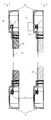
- Fig. 1 sin the end portions of serving as a protective jacket coil spring 11 in a correspondingly shaped receiving opening of the head piece 13 or 14 used.
- the Receiving opening for the spring end has a helical inner profile, in which the Spring end screwed and thus non-positively connected to the head piece. to Securing a position at the spring end molded eyelet 18 by an inside at the bottom of the Headpiece 13 and 14 fastened blind rivet 16 and 17 anchored to the head piece. Instead you can shrink the head piece on the spring end, in the case of a metallic Head piece soldered or welded to the spring end, a head piece made of plastic stick together with the spring end or a secure position between the two parts in other ways make mechanical connection. This also applies to the wound protective tube 12 in Fig.2.
- Wire rope 15 preferably a steel wire rope of high tensile strength, with its ends on respective head piece 13 and 14 is anchored.
- Wire rope 15 preferably a steel wire rope of high tensile strength, with its ends on respective head piece 13 and 14 is anchored.
- the same blind rivet 16 and 17, the shaft of the holding eye 18 of the spring end is entwined.
- the wire ends are to a retaining loop or tether 19th bent and hooked on the respective head piece, namely the blind rivet 16.
- the attachment of the wire 15 and / or the spring ends on the head piece 13,14 can also done in other ways, for example by screws or hooks.
- the molding can for example, hook or T-shaped shape.
- Other simple forms of Wire rope attachment are known for example from Bowden cables on the bicycle. Type and form The attachment depends primarily on the forces and the space available within the header.
- the additional wire 15 inside the protective jacket, the tensile strength of the cable transition increases considerably, without while noticeably reducing its clear cross section.
- the wire 15 or another elongated securing element with high tensile strength in the longitudinal direction hinders due its flexibility transverse to the longitudinal axis the movement of the cable transition when opening and Close the window or door not.
- the coil spring 11 consists e.g. made of steel or Brass.
- Figure 2 is used instead of a coil spring, a wound plastic or metal tube 12th as a protective coat.
- a wound plastic or metal tube 12th As a protective coat.
- PVC sheathed or metallized in the case of a plastic hose.
- head pieces 13 and 14 Also in this embodiment provides the inserted cable 15 with little effort for increased security against damage or even destruction of the cable transition and in particular the electrical running therein Cable. You get a much better vandalism than hitherto protected Cable transition, without this being visible from the outside.
- the invention can not only how shown, with exposed cable transitions but also with advantage in hidden Cable transitions are used, as known for example from DE 200 15 428 U1 are.
- the protective jacket for the cable 20 consists, as in FIG. 1, of from a tightly wound coil spring 11, at the ends here each a crosspiece forming or exhibiting molded part, preferably a holding eye 18, is provided. With this molding 18, the respective coil spring end 22 in a already with reference to Fig. Illustrated manner attached to the adjacent head piece 13.
- a strap 23 is provided at each end of the wire 15 . It easily gets over the holding lug 18 or another molding at the end of the coil spring 11 on the between Slide fitting 18 and winding end 22 located neck piece 21. That way you can Protective spring 11 and wire 15 are captively preassembled, the retaining strap 23rd loosely seated on the spring neck 21 and consequently neither the subsequent insertion of the cable 20 or the Fixing the retaining lug 18 on the head piece 13 of the cable transition nor the deformation of Cable transition obstructed during operation.
- the cable 20 is protective Coil spring 11 reproduced at the winding end 22, the holding lug 18 preferably is integrally formed.
- the end of serving as Switzerlandfeld cable 15 is one Hand strap 23 is bent over and welded or clamped to the wire rope, e.g. by means of a sleeve with the wire pressed, so that the retaining loop not without destroying the Wire rope is detachable.
- This strap 23 is about the holding eye 18 and the neck 21st pushed and wrapped around this loose.
- With a screw or a rivet 16 is the holding lug 18 and thus the coil spring end 22 together with wire end 23 either at the window or Window frame or, as shown in Figure 4, attached to the head piece 13.
- the head piece in turn, by means of inserted in one or two holes 24 screws on or movable support, e.g. Window frame or sash, is attached.
- the wire rope 15 extends in the interior of the protective jacket in the form of the coil spring 11 parallel to Usually multicore cable 20.
- the holder of the wire ends by means of a loose the Neck 21 of the coil spring 11 looping around strap 23 allows a simple, Captive pre-assembly of coil spring 11 and wire 15 and gives this in Fig.3 shown preassembled module at the same time enough flexibility for their installation in the Head pieces and finally for their attachment to the movable or on the stationary support.
- This development of the invention can also be applied when the attachment of the Federendes 22 on the head piece 13 not by means of a holding lug but by a differently shaped Cross piece at the spring end.
- the retaining loop of the wire rope is placed between a cross piece and winding end of the coil spring located neck piece.
- the Holder of the wire ends by means of a retaining loop on the ends of the coil spring is particularly cost-effective and mechanically flexible.
- a blind rivet 16 or one Screw can also be attached to the inside of the header floor, preferably Molded hook holding the eyelet of the coil spring. Then it is recommended by a the open side of the hook covering, rectified to the bore 24 second Fixing screw to prevent the sliding of the retaining lug 18 from the hook.
Landscapes
- Flexible Shafts (AREA)
- Insulated Conductors (AREA)
Abstract
Description
- Fig. 1
- im Längsschnitt einen flexiblen Kabelübergang mit einer dicht gewickelten Schraubenfeder als Schutzmantel und einem Drahtseil als Sicherungselement;
- Fig.2
- eine Ausführungsform mit einem gewickelten Schutzschlauch;
- Fig.3
- in perspektivischer Darstellung die dicht gewickelte Schraubenfeder mit eingelegtem Drahtseil sowie einer über den Hals einer Halteöse der Schraubenfeder geschobenen Halteschlaufe des Drahtseils; und
- Fig.4
- im Längsschnitt ein Kopfstück eines solchen Kabelübergangs mit Kabel und Drahtseil.
Claims (12)
- Flexibler Kabelübergang zwischen einem ortsfesten und einem gegenüber diesem schwenkbaren Träger, insbesondere zwischen Fensterrahmen und Fensterflügel, Türrahmen und Tür oder dergl., mit einem das Kabel umgebenden flexiblen Schutzmantel (11;12) sowie mit Vorrichtungen (13,14) zum Befestigen der Schutzmantelenden am ortsfesten bzw. schwenkbaren Träger,
dadurch gekennzeichnet, daß innerhalb des Schutzmantels (11;12) ein langgestrecktes, quer zu seiner Längsrichtung flexibles und in Längsrichtung zugfestes Sicherungselement (15) angeordnet und mit seinen Enden am ortsfesten und am schwenkbaren Träger befestigbar ist. - Kabelübergang nach Anspruch 1, dadurch gekennzeichnet, daß mindestens eines der Enden des Sicherungselements (15) an einem der Befestigung des Schutzmantelendes am ortsfesten bzw. schwenkbaren Träger dienenden Kopfstück (13,14) befestigt ist.
- Kabelübergang nach Anspruch 1 oder 2, dadurch gekennzeichnet, daß als langgestrecktes Sicherungselement ein Draht oder ein Drahtseil (15) dient.
- Kabelübergang nach Anspruch 3, dadurch gekennzeichnet, daß der Draht bzw. das Drahtseil (15) an wenigstens einem Ende mit einem ein Querstück bildenden oder aufweisenden Formteil (19) versehen ist.
- Kabelübergang nach einem der Ansprüche 1 bis 4, dadurch gekennzeichnet, daß der Schutzmantel ein gewickelter Kunststoff- oder Metallschlauch (12) ist.
- Kabelübergang nach einem der Ansprüche 1 bis 4, dadurch gekennzeichnet, daß der Schutzmantel eine dicht gewickelte Schraubenfeder (11) ist.
- Kabelübergang nach Anspruch 3 und 6, mit je einem ein Querstück bildenden oder aufweisenden Formteil (18) an den Enden der Schraubenfeder (11), sowie je einer Vorrichtung (16,17) zum Befestigen dieses Formteils am ortsfesten bzw. schwenkbaren Träger;
dadurch gekennzeichnet, daß das Drahtseil (15) an seinen Enden mit je einer Halteschlaufe (23) versehen ist, welche jeweils ein zwischen Formteil (18) und Wickelende (22) der Schraubenfeder (11) befindliches Halsstück (21) der Schraubenfeder lose umschlingt. - Kabelübergang nach Anspruch 7, dadurch gekennzeichnet, daß jede Halteschlaufe (23) durch ein rückgebogenes und festgeklemmtes Drahtende gebildet ist.
- Kabelübergang nach Anspruch 4 oder 7, dadurch gekennzeichnet, daß wenigstens eines der Formteile (19,18) haken- oder T-förmig ist.
- Kabelübergang nach Anspruch 4 oder 7, dadurch gekennzeichnet, daß wenigstens eines der Formteile (19,18) eine Halteöse ist.
- Kabelübergang nach Anspruch 4 oder 7, dadurch gekennzeichnet, daß wenigstens eines der Formteile (19,18) einstückig an das Drahtseil (15) bzw. die Schraubenfeder (11) angeformt ist.
- Kabelübergang nach Anspruch 4 oder 7, dadurch gekennzeichnet, daß wenigstens eines der Formteile (19,18) durch eine Schraube, einen Haken oder einen Blindniet (16,17) am Kopfstück (13,14) gehalten ist.
Applications Claiming Priority (4)
| Application Number | Priority Date | Filing Date | Title |
|---|---|---|---|
| DE10234413A DE10234413C1 (de) | 2002-07-29 | 2002-07-29 | Flexibler Kabelübergang |
| DE10234413 | 2002-07-29 | ||
| DE20308584U | 2003-06-02 | ||
| DE20308584U DE20308584U1 (de) | 2003-06-02 | 2003-06-02 | Flexibler Kabelübergang mit Schraubenfeder als Schutzmantel |
Publications (3)
| Publication Number | Publication Date |
|---|---|
| EP1387458A2 true EP1387458A2 (de) | 2004-02-04 |
| EP1387458A3 EP1387458A3 (de) | 2005-01-19 |
| EP1387458B1 EP1387458B1 (de) | 2006-08-30 |
Family
ID=30116653
Family Applications (1)
| Application Number | Title | Priority Date | Filing Date |
|---|---|---|---|
| EP03016946A Expired - Lifetime EP1387458B1 (de) | 2002-07-29 | 2003-07-25 | Kabelübergang mit flexiblem Schutzmantel |
Country Status (2)
| Country | Link |
|---|---|
| EP (1) | EP1387458B1 (de) |
| DE (1) | DE50304825D1 (de) |
Cited By (2)
| Publication number | Priority date | Publication date | Assignee | Title |
|---|---|---|---|---|
| DE102012005540A1 (de) | 2012-03-21 | 2013-09-26 | Link Gmbh | Kabelübergang aus einem Stranggussformteil |
| CN107830131A (zh) * | 2017-11-23 | 2018-03-23 | 苏州爱康金属科技有限公司 | 太阳能柔性传动逐日系统 |
Family Cites Families (4)
| Publication number | Priority date | Publication date | Assignee | Title |
|---|---|---|---|---|
| FI60057C (fi) * | 1980-02-20 | 1981-11-10 | Waertsilae Oy Ab | Anordning vid doerr |
| DE29814952U1 (de) * | 1998-08-20 | 1999-12-30 | Elektro-Special-Bedarf Norbert Link GmbH, 35510 Butzbach | Flexibler Kabelübergang |
| DE20015428U1 (de) * | 2000-09-06 | 2002-01-17 | Elektro-Special-Bedarf Link GmbH, 35510 Butzbach | Verdeckter Kabelübergang mit Einbaugehäuse |
| DE10053153C1 (de) * | 2000-10-26 | 2002-06-27 | Elektro Special Bedarf Link Gm | Trennbarer Kabelübergang |
-
2003
- 2003-07-25 EP EP03016946A patent/EP1387458B1/de not_active Expired - Lifetime
- 2003-07-25 DE DE50304825T patent/DE50304825D1/de not_active Expired - Lifetime
Cited By (3)
| Publication number | Priority date | Publication date | Assignee | Title |
|---|---|---|---|---|
| DE102012005540A1 (de) | 2012-03-21 | 2013-09-26 | Link Gmbh | Kabelübergang aus einem Stranggussformteil |
| CN107830131A (zh) * | 2017-11-23 | 2018-03-23 | 苏州爱康金属科技有限公司 | 太阳能柔性传动逐日系统 |
| CN107830131B (zh) * | 2017-11-23 | 2024-02-23 | 苏州爱康金属科技有限公司 | 太阳能柔性传动逐日系统 |
Also Published As
| Publication number | Publication date |
|---|---|
| EP1387458B1 (de) | 2006-08-30 |
| DE50304825D1 (de) | 2006-10-12 |
| EP1387458A3 (de) | 2005-01-19 |
Similar Documents
| Publication | Publication Date | Title |
|---|---|---|
| DE69933620T2 (de) | Struktur zum Schutz eines biegsamen Flachkabels | |
| DE60200068T2 (de) | Fahrzeugtürscharnierkabelbaum | |
| DE102004051363A1 (de) | Dauer-Energieversorgungseinrichtung | |
| DE1966107A1 (de) | Kabelbinder | |
| DE60107000T2 (de) | Vorrichtung zum Tragen und Führen eines Bündels elektrischer Leiter, welche das Folgen von Bewegungen eines Vordersitzes eines Kraftfahrzeugs gestatten | |
| DE602005002716T2 (de) | Haltevorrichtung | |
| EP2634344B1 (de) | Antrieb für einen Flügel eines Fensters oder dergleichen sowie ein Verfahren zur Montage einer Endkappe des Antriebs | |
| DE1955961B2 (de) | Kabelbefestigung | |
| DE60202733T2 (de) | Nachstellvorrichtung für Kabelbäume | |
| DE9205811U1 (de) | Steckverbindung, insbesondere für den elektrischen Anschluß von Anhängerfahrzeugen | |
| DE102006055368B4 (de) | Stromversorgungsanordnung für eine Schiebestruktur | |
| DE4430770B4 (de) | Messfühler zur einfachen Befestigung an einem Rohr | |
| DE3110298A1 (de) | "vorrichtung zum einklemmen eines kabels" | |
| DE2840235A1 (de) | Flachkabelaufhaengung | |
| EP1387458B1 (de) | Kabelübergang mit flexiblem Schutzmantel | |
| DE10234413C1 (de) | Flexibler Kabelübergang | |
| DE102014006061B4 (de) | Elektrisch leitendes Gehäuse mit Kabelzugentlastung und Schirmanbindung | |
| DE29814952U1 (de) | Flexibler Kabelübergang | |
| DE102012203246B4 (de) | Antrieb für einen Flügel eines Fensters oder dergleichen sowie ein Verfahren zur Montage des Antriebs | |
| DE20308584U1 (de) | Flexibler Kabelübergang mit Schraubenfeder als Schutzmantel | |
| DE10162036C1 (de) | Vorrichtung zum Heben und Senken einer Fensterscheibe in einem Kraftfahrzeug | |
| DE102006010765B4 (de) | Bandhaken und Weidezaunbreitbandbefestigungsvorrichtung | |
| DE102004018005A1 (de) | Mitnehmer für Seilzug-Fensterheber für eine Fensterscheibe eines Kraftfahrzeuges | |
| DE29521187U1 (de) | Anschlußglied für eine Energieführungskette | |
| DE102006019381A1 (de) | Schiebetür für ein Kraftfahrzeug |
Legal Events
| Date | Code | Title | Description |
|---|---|---|---|
| PUAI | Public reference made under article 153(3) epc to a published international application that has entered the european phase |
Free format text: ORIGINAL CODE: 0009012 |
|
| AK | Designated contracting states |
Kind code of ref document: A2 Designated state(s): AT BE BG CH CY CZ DE DK EE ES FI FR GB GR HU IE IT LI LU MC NL PT RO SE SI SK TR |
|
| AX | Request for extension of the european patent |
Extension state: AL LT LV MK |
|
| RAP1 | Party data changed (applicant data changed or rights of an application transferred) |
Owner name: LINK GMBH |
|
| PUAL | Search report despatched |
Free format text: ORIGINAL CODE: 0009013 |
|
| AK | Designated contracting states |
Kind code of ref document: A3 Designated state(s): AT BE BG CH CY CZ DE DK EE ES FI FR GB GR HU IE IT LI LU MC NL PT RO SE SI SK TR |
|
| AX | Request for extension of the european patent |
Extension state: AL LT LV MK |
|
| 17P | Request for examination filed |
Effective date: 20050524 |
|
| AKX | Designation fees paid |
Designated state(s): DE FR GB IT |
|
| GRAP | Despatch of communication of intention to grant a patent |
Free format text: ORIGINAL CODE: EPIDOSNIGR1 |
|
| GRAS | Grant fee paid |
Free format text: ORIGINAL CODE: EPIDOSNIGR3 |
|
| GRAA | (expected) grant |
Free format text: ORIGINAL CODE: 0009210 |
|
| AK | Designated contracting states |
Kind code of ref document: B1 Designated state(s): DE FR GB IT |
|
| PG25 | Lapsed in a contracting state [announced via postgrant information from national office to epo] |
Ref country code: IT Free format text: LAPSE BECAUSE OF FAILURE TO SUBMIT A TRANSLATION OF THE DESCRIPTION OR TO PAY THE FEE WITHIN THE PRESCRIBED TIME-LIMIT;WARNING: LAPSES OF ITALIAN PATENTS WITH EFFECTIVE DATE BEFORE 2007 MAY HAVE OCCURRED AT ANY TIME BEFORE 2007. THE CORRECT EFFECTIVE DATE MAY BE DIFFERENT FROM THE ONE RECORDED. Effective date: 20060830 |
|
| REG | Reference to a national code |
Ref country code: GB Ref legal event code: FG4D Free format text: NOT ENGLISH |
|
| REF | Corresponds to: |
Ref document number: 50304825 Country of ref document: DE Date of ref document: 20061012 Kind code of ref document: P |
|
| ET | Fr: translation filed | ||
| PLBE | No opposition filed within time limit |
Free format text: ORIGINAL CODE: 0009261 |
|
| STAA | Information on the status of an ep patent application or granted ep patent |
Free format text: STATUS: NO OPPOSITION FILED WITHIN TIME LIMIT |
|
| 26N | No opposition filed |
Effective date: 20070531 |
|
| REG | Reference to a national code |
Ref country code: FR Ref legal event code: PLFP Year of fee payment: 13 |
|
| REG | Reference to a national code |
Ref country code: FR Ref legal event code: PLFP Year of fee payment: 14 |
|
| REG | Reference to a national code |
Ref country code: FR Ref legal event code: PLFP Year of fee payment: 15 |
|
| REG | Reference to a national code |
Ref country code: FR Ref legal event code: PLFP Year of fee payment: 16 |
|
| PGFP | Annual fee paid to national office [announced via postgrant information from national office to epo] |
Ref country code: IT Payment date: 20190723 Year of fee payment: 17 |
|
| PGFP | Annual fee paid to national office [announced via postgrant information from national office to epo] |
Ref country code: GB Payment date: 20190725 Year of fee payment: 17 |
|
| GBPC | Gb: european patent ceased through non-payment of renewal fee |
Effective date: 20200725 |
|
| PG25 | Lapsed in a contracting state [announced via postgrant information from national office to epo] |
Ref country code: GB Free format text: LAPSE BECAUSE OF NON-PAYMENT OF DUE FEES Effective date: 20200725 |
|
| PGFP | Annual fee paid to national office [announced via postgrant information from national office to epo] |
Ref country code: FR Payment date: 20210721 Year of fee payment: 19 |
|
| PGFP | Annual fee paid to national office [announced via postgrant information from national office to epo] |
Ref country code: DE Payment date: 20210726 Year of fee payment: 19 |
|
| PG25 | Lapsed in a contracting state [announced via postgrant information from national office to epo] |
Ref country code: IT Free format text: LAPSE BECAUSE OF NON-PAYMENT OF DUE FEES Effective date: 20200725 |
|
| REG | Reference to a national code |
Ref country code: DE Ref legal event code: R119 Ref document number: 50304825 Country of ref document: DE |
|
| PG25 | Lapsed in a contracting state [announced via postgrant information from national office to epo] |
Ref country code: FR Free format text: LAPSE BECAUSE OF NON-PAYMENT OF DUE FEES Effective date: 20220731 |
|
| PG25 | Lapsed in a contracting state [announced via postgrant information from national office to epo] |
Ref country code: DE Free format text: LAPSE BECAUSE OF NON-PAYMENT OF DUE FEES Effective date: 20230201 |