EP1385716B1 - Verfahren und vorrichtung zur bestimmung einer position eines durch eine antriebsvorrichtung verstellbaren teils eines kraftfahrzeugsitzes - Google Patents
Verfahren und vorrichtung zur bestimmung einer position eines durch eine antriebsvorrichtung verstellbaren teils eines kraftfahrzeugsitzes Download PDFInfo
- Publication number
- EP1385716B1 EP1385716B1 EP02740330A EP02740330A EP1385716B1 EP 1385716 B1 EP1385716 B1 EP 1385716B1 EP 02740330 A EP02740330 A EP 02740330A EP 02740330 A EP02740330 A EP 02740330A EP 1385716 B1 EP1385716 B1 EP 1385716B1
- Authority
- EP
- European Patent Office
- Prior art keywords
- drive device
- parameter
- evaluated
- mot
- correction
- Prior art date
- Legal status (The legal status is an assumption and is not a legal conclusion. Google has not performed a legal analysis and makes no representation as to the accuracy of the status listed.)
- Expired - Lifetime
Links
- 238000000034 method Methods 0.000 title claims description 34
- 238000012937 correction Methods 0.000 claims description 42
- 230000033001 locomotion Effects 0.000 claims description 34
- 238000011156 evaluation Methods 0.000 claims description 23
- 238000006073 displacement reaction Methods 0.000 claims description 15
- 239000000654 additive Substances 0.000 claims description 4
- 230000000996 additive effect Effects 0.000 claims description 4
- 230000005540 biological transmission Effects 0.000 description 12
- 230000027455 binding Effects 0.000 description 8
- 238000009739 binding Methods 0.000 description 8
- 230000008878 coupling Effects 0.000 description 7
- 238000010168 coupling process Methods 0.000 description 7
- 238000005859 coupling reaction Methods 0.000 description 7
- 230000001419 dependent effect Effects 0.000 description 5
- 230000006870 function Effects 0.000 description 5
- 230000008569 process Effects 0.000 description 5
- 238000011161 development Methods 0.000 description 3
- 230000018109 developmental process Effects 0.000 description 3
- 230000005489 elastic deformation Effects 0.000 description 3
- 230000000903 blocking effect Effects 0.000 description 2
- 239000011159 matrix material Substances 0.000 description 2
- 230000004044 response Effects 0.000 description 2
- 230000000712 assembly Effects 0.000 description 1
- 238000000429 assembly Methods 0.000 description 1
- 230000006399 behavior Effects 0.000 description 1
- 238000005452 bending Methods 0.000 description 1
- 230000008901 benefit Effects 0.000 description 1
- 238000004364 calculation method Methods 0.000 description 1
- 230000008859 change Effects 0.000 description 1
- 230000009977 dual effect Effects 0.000 description 1
- 230000006698 induction Effects 0.000 description 1
- 238000005259 measurement Methods 0.000 description 1
- 230000007246 mechanism Effects 0.000 description 1
- 238000003825 pressing Methods 0.000 description 1
- 238000012545 processing Methods 0.000 description 1
- 238000013519 translation Methods 0.000 description 1
- 230000002618 waking effect Effects 0.000 description 1
Images

Classifications
-
- B—PERFORMING OPERATIONS; TRANSPORTING
- B60—VEHICLES IN GENERAL
- B60N—SEATS SPECIALLY ADAPTED FOR VEHICLES; VEHICLE PASSENGER ACCOMMODATION NOT OTHERWISE PROVIDED FOR
- B60N2/00—Seats specially adapted for vehicles; Arrangement or mounting of seats in vehicles
- B60N2/02—Seats specially adapted for vehicles; Arrangement or mounting of seats in vehicles the seat or part thereof being movable, e.g. adjustable
- B60N2/0224—Non-manual adjustments, e.g. with electrical operation
- B60N2/02246—Electric motors therefor
-
- B—PERFORMING OPERATIONS; TRANSPORTING
- B60—VEHICLES IN GENERAL
- B60N—SEATS SPECIALLY ADAPTED FOR VEHICLES; VEHICLE PASSENGER ACCOMMODATION NOT OTHERWISE PROVIDED FOR
- B60N2/00—Seats specially adapted for vehicles; Arrangement or mounting of seats in vehicles
- B60N2/02—Seats specially adapted for vehicles; Arrangement or mounting of seats in vehicles the seat or part thereof being movable, e.g. adjustable
- B60N2/0224—Non-manual adjustments, e.g. with electrical operation
- B60N2/02246—Electric motors therefor
- B60N2/02253—Electric motors therefor characterised by the transmission between the electric motor and the seat or seat parts
-
- B—PERFORMING OPERATIONS; TRANSPORTING
- B60—VEHICLES IN GENERAL
- B60N—SEATS SPECIALLY ADAPTED FOR VEHICLES; VEHICLE PASSENGER ACCOMMODATION NOT OTHERWISE PROVIDED FOR
- B60N2/00—Seats specially adapted for vehicles; Arrangement or mounting of seats in vehicles
- B60N2/02—Seats specially adapted for vehicles; Arrangement or mounting of seats in vehicles the seat or part thereof being movable, e.g. adjustable
- B60N2/0224—Non-manual adjustments, e.g. with electrical operation
- B60N2/0244—Non-manual adjustments, e.g. with electrical operation with logic circuits
-
- B—PERFORMING OPERATIONS; TRANSPORTING
- B60—VEHICLES IN GENERAL
- B60N—SEATS SPECIALLY ADAPTED FOR VEHICLES; VEHICLE PASSENGER ACCOMMODATION NOT OTHERWISE PROVIDED FOR
- B60N2/00—Seats specially adapted for vehicles; Arrangement or mounting of seats in vehicles
- B60N2/002—Seats provided with an occupancy detection means mounted therein or thereon
- B60N2/0021—Seats provided with an occupancy detection means mounted therein or thereon characterised by the type of sensor or measurement
- B60N2/0024—Seats provided with an occupancy detection means mounted therein or thereon characterised by the type of sensor or measurement for identifying, categorising or investigation of the occupant or object on the seat
- B60N2/0025—Seats provided with an occupancy detection means mounted therein or thereon characterised by the type of sensor or measurement for identifying, categorising or investigation of the occupant or object on the seat by using weight measurement
-
- B—PERFORMING OPERATIONS; TRANSPORTING
- B60—VEHICLES IN GENERAL
- B60N—SEATS SPECIALLY ADAPTED FOR VEHICLES; VEHICLE PASSENGER ACCOMMODATION NOT OTHERWISE PROVIDED FOR
- B60N2210/00—Sensor types, e.g. for passenger detection systems or for controlling seats
- B60N2210/10—Field detection presence sensors
- B60N2210/14—Inductive; Magnetic field
-
- B—PERFORMING OPERATIONS; TRANSPORTING
- B60—VEHICLES IN GENERAL
- B60N—SEATS SPECIALLY ADAPTED FOR VEHICLES; VEHICLE PASSENGER ACCOMMODATION NOT OTHERWISE PROVIDED FOR
- B60N2230/00—Communication or electronic aspects
- B60N2230/30—Signal processing of sensor data
Definitions
- the invention relates to a method and a device for determining a position an adjustable by an electric drive device part of a Motor vehicle seat.
- an engine seat device which has a Displacement motor for moving a motor vehicle seat in forward or Reverse direction, a lifting motor for moving the seat upwards and downwards below and a tilt motor to adjust a tilt angle of the backrest of the Seat has.
- a preset memory operating data of the corresponding motors stored in response to a preset operation.
- a storage drive device drives the motors according to the operating data stored in the preset memory. Based on an operation of a Manual switching device, the motors by a manual drive device driven.
- the motors are controlled by a control mechanism by processing the operating data provided by the respective engines during their Inertia rotations are emitted as signals in the same direction as immediately before the inertia rotations of the respective engines, in one case the Actuation of the manual switching device, when the motors of the Storage drive device to be driven.
- the invention is based on the object during the operation of an electrical Drive device occurring errors in the position measurement of an adjustable part to correct a motor vehicle seat.
- the adjustable part by the drive device directly ie without a Power transmission via transmission elements or coupling elements, driven, could Movement of the drive device and the adjustable part take place synchronously.
- drive torque in particular Drive torque
- drive speed in particular the speed of the Drive
- transmission elements and coupling elements used that a translation too To allow lower speeds or higher torques.
- electric motors with a rotating rotor can also drive other devices, such as linear motors or hydraulics corresponding transmission means used.
- the driving force of the driving device causes elastic deformation, for example the transmission elements or the coupling elements. These elastic deformations lead to a deviation of the proportionality between the drive movement of Drive device and the adjustment of the adjustable part. Based on these Deviation from proportionality move until the elasticity is stretched Drive device and the adjustable part asynchronous. This temporary asynchrony leads to a difference between the drive movement determined by the signal and the movement of the adjustable part and thus to a position error of the current Position of the adjustable part.
- a signal is evaluated, which in Dependence on a drive movement, in particular a rotation of a Drive axle of an electric motor is generated.
- the signal is for Rotation angle proportional voltage signal, current signal or frequency signal.
- digital, a certain angle of rotation or a Drive train characterizing pulses evaluated. These pulses will be in particular generated by at least one Hall sensor, wherein, for example, on the drive shaft arranged magnet acts as a donor of the measuring system.
- perforated disks can be used to different angles of rotation to detect.
- the signal evaluated is the signal evaluated.
- the signal for example by means of an analog-to-digital converter, quantized or the analog signal is by means of a threshold switch transformed into digital impulses.
- the computationally evaluable signals are in a microcontroller for evaluation, for example counted and certain positions associated with the adjustable part.
- the signals are advantageously used for Determination of memory positions of the adjustments and automatic Appropriately approaching the memory positions, as described for example in DE 41 08 295 A1 is described.
- the generation of the signals takes place within, or in the vicinity of Drive device to further additional wiring to other locations of the Save adjusting system positioned sensors.
- the ripple of the motor current is evaluated as a signal.
- the on Known ripple counting method is with the inventive correction of Position errors apply particularly advantageous, as well as a correction to Shutdown of the motor current is possible.
- Essential to the invention is the evaluation of a parameter in addition to already mentioned signal.
- the characteristic can not alone from the drive movement be generated, but requires another, independent of the signal size, for example, a time size of a clock or other timer.
- the time variable is used as a parameter or the time size in combination with the Signal evaluated as a parameter used to determine and evaluate a Speed of the adjustable part is used.
- the characteristic characterizes Properties of the adjustment or make at least one influencing the adjustment Size off. Based on the example above, the speed of a unregulated drive device as a measure of stiffness of the adjustment and thus evaluated to determine the extent of elastic deformation.
- the correction of the position error allows a variety of influences on the Asynchronism between the drive device and the adjustable part computationally compensate.
- the correction of the position error with Help of an algorithm, empirically determined values or others, for example successive process. Special developments of the correction become the following explained.
- the position error in dependence corrected by a class assigned to the correction is advantageously by comparing the one or more characteristics determined with one or more thresholds.
- the values to be corrected for this Correction case relevant class are measured, calculated and / or out following read out a memory.
- each class is a Correction factor assigned to correct the position error.
- correction factors serve for example a positive and a negative sign. Will in this example used as characteristic the control signal for energizing the drive device, For the class "negative", valid after power supply, the incoming signals become Movement of the drive unit with the correction factor "- 1", ie negatively weighted, since due to the relaxation of the elasticity, the drive axis against the Adjustment moves and at the beginning of the adjustment for the tensioning of the elasticity the same absolute position error arises.
- data of the signal is converted into additive data and subtractive data divided. Following is the current position according to the additive data in Adjustment direction or subtractive data corrected against the adjustment.
- the correction factor is a proportionality factor.
- the class becomes determined by a torque of the drive device as a parameter is in a range of the elasticity of the position error proportional to the torque of the Drive device. This proportional portion of the position error becomes the shutdown the motor current is corrected by means of the correction factor.
- correction factors and correction constants are other functional Connections, such as square functions or root functions are conceivable.
- functional relationships are used to correct the signal in To weight dependence on the parameter.
- the weighting is not on one Classification limited, but evaluates alternatively using For example, continuous functions output the signal.
- data of the signal is added to the weighting subdividing data or into data that has been expired for correction.
- This enables a particularly fast correction and updating of the position according to the data to be evaluated.
- the position error becomes continuous determined in relation to the torque of the drive device.
- this increases Torque of the drive device due to a stiffness of the adjustment on, so the elasticity of an elastic coupling is stretched more.
- the data of the signal for weighting are distributed differently by a greater percentage of expired data to correct for greater binding be assigned.
- a particularly advantageous embodiment of the invention provides that as signals Pulses are evaluated, which depend on the drive movement, in particular a rotation angle of the drive movement, are generated. To Evaluation, the pulses are counted and added according to the adjustment or subtracted. For correction, the count of the pulses is corrected.
- a parameter is a Drive size, such as a control signal for the energization of the drive device according to the adjustment, a duty cycle of a pulse width modulation for Control of the drive speed, a voltage of the motor vehicle battery, a Adjustment time or the number of pulses of the signal within a time unit, the Time interval between two pulses, a temperature of the drive device or the Adjustment system, a motor current or a measured or calculated Torque of the drive device evaluated.
- the parameter is preferably determined cyclically and continuously updated in a memory. To update you can Preferably, moving average values are also formed. Become some characteristic Alternatively, only shortly before switching off the motor current determined and following in the Calculation included.
- an operating variable is additionally used as a parameter.
- the farm size depends on external operating influences on the adjustment.
- the farm size is detected, such as a seat occupancy, a seat occupant seat weight, a Distribution of the single-seat weight or an ambient temperature and for correction evaluated.
- the seat occupant's seat weight is an essential one Size that influences the stiffness of the adjustment. The determination of the One-seat weight can already early, especially after the entry of the Wegbenutzer and closing the vehicle door done.
- the binding of the adjustment advantageously be in addition to over determined the entire possible adjustment and stored in a memory. Based on the known bindings is a correction for the corresponding Adjustment range possible by using as a parameter according to the positions for the Bindings stored data of the adjustment system are evaluated.
- Characteristic evaluated at least one significant characteristic of the adjustment is, for example, the determination of elasticity for a Blocking the adjustable part.
- Et al will also be possible significant Bindings, easy movements or a known game of the adjustment as Characteristic recorded.
- a parameter is a combination of one or more Operating variables, one or more drive variables, stored bindings and / or one or more significant characteristics.
- This is for example, for correction, an x-dimensional class matrix is used, where x is the Number of combined characteristics to be evaluated. So, the correction becomes a Class of the class matrix based on the temperature of the drive device, the Momentary torque of the drive device, the change of the Driving torque and the single-seat weight, and the distribution of the single-seat weight certainly.
- the drive movement determined by means of a single-channel sensor determined by means of a single-channel sensor.
- the single-channel sensor for example a Hall sensor, requires only two additional cables to be laid without one Evaluation should be integrated into the sensor.
- a signal becomes a non-directionally detectable Sensor signal of the single-channel sensor evaluated.
- the Direction can not be determined by a single Hall sensor is a Characteristic, for example, the control signal for the direction of energization of Drive device, with evaluated.
- the sensors without the evaluation of an additional characteristic not in the Able to distinguish the direction of rotation of the drive axle, since the generated pulses regardless of the direction of rotation.
- the method according to the invention increases the position repeatability the adjustment system, in particular with a single-Hall sensor achieved without the more complex and thus more costly Hall elements, e.g. Double reverb systems must be used.
- An increase in position repeatability in turn reduces the likelihood that the Adjustment system in a block, that is driven in an end stop. Since that Blocking is a high load of electric motors and the gearbox can do so particularly advantageous reduces the wear of the electric motors and the transmission become. Nevertheless, if a block driving, so is advantageously the Position determination re-normalized at this point. Further reduced by the Use of individual hall systems of the cabling expenditure for the drive devices, since no direction information must be transmitted.
- the characteristic is in an advantageous development of the invention in a dual function for correcting a position error and for detecting jamming of a Evaluated object or human body part. Become particular evaluated several characteristics, so can from the single-seat weight, from the expected Stiffness of the adjustment system and from the current binding of the Adjustment system a pinching case can be detected.
- the seat 1 shows a seat underframe with a plurality of motor-driven adjustment paths. It consists essentially of a pair of rail guides 1 whose lower rails 10 are fixed to the vehicle floor and the top rails 11 the seat structure with all Wear drive units.
- For electrical longitudinal adjustment includes gear 31, the be driven indirectly by the motor 61 or indirectly via a flexible shaft 9.
- the Rear seat height adjustment is driven by the motor 61 via a gear 32, wherein the adjusting force is transmitted to the connecting shaft 17, which at their ends in rotationally fixed connection with the drive levers 20 stands.
- the ends of the drive lever 20 engage over the pivot bearings 40 at the rear ends of the side panels 22, so that a pivoting movement of the lever 20 to an up or down movement of the rear Side plate 22 leads.
- the gear 30 serves only to adjust the seat depth and has only a minor impact on the crash safety of the seat.
- the front seat height adjustment works in a similar way using another Motor via a gear 33 and another connecting shaft via the lever arms 21st and 210.
- Both Gurtanschlagsread 220 and 221 of the seat frame are on the Side parts 22 arranged.
- About the Gurtanschlagsucc is in the event of a crash the Crash force introduced into the seat frame, the desired and undesirable Deformations of parts or assemblies, such as an extension of a Angled contour and a bending and thus a forward displacement in Guide load direction.
- FIG 1 shows a coordinate system, wherein the x-direction in the direction of travel, the y-direction transverse to the direction of travel and the z-direction upwards, perpendicular to the xy-plane.
- the Transmission 30, 31, 32 and 33 and the flexible shaft 9 are for an adjustment deformed elastically until the adjusting force acting on the adjustment is greater than that Self - locking, or the friction force of the binding of the Adjustment system.
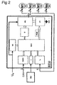
- FIG. 2 shows an evaluation device ECU and four motors M1 to M4, each with a Hall sensor H1 to H4.
- a unit of electric motor M1 and Hall sensor H1, respectively M2, M3, M4 and H2, H3 and H4 is connected to the evaluation device ECU via four lines (4) of a connection. Two of these lines are connected to the transmission of the motor current to the power relay 'PR of the evaluation ECU. The other two lines are connected to the interface I H for the Hall sensors H1 to H4 of the evaluation ECU.
- the signals of the Hall sensors H1 to H4 are converted in the interface I H into computationally processable pulses and forwarded to the microcontroller MCU of the evaluation ECU.
- the microcontroller controls the power relay 'PR via a driver D.
- the microcontroller MCU generates a pulse width modulated control signal PWM for driving the power transistors PT.
- the power transistors PT serve to control the respective motor current and are connected to the power relay '.
- the microcontroller MCU has an integrated flash memory.
- the microcontroller MCU is connected to a voltage U B of the motor vehicle battery voltage supply VS, which supplies the microcontroller with the operating voltage of usually 5V.
- the power supply VS has a watchdog for waking up the evaluation device ECU from a standby mode.
- microcontroller MCU is connected to an input interface I that a Interface to an actuating device SU, in particular a switch block SU, for driving the electric motors M1 to M4 forms.
- a Interface to an actuating device SU, in particular a switch block SU, for driving the electric motors M1 to M4 forms.
- Another interface CAN-I connects the microcontroller MCU to a CAN bus that has an information and Data exchange with other functional units of the motor vehicle allows.
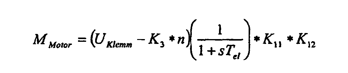
- FIG. 3 shows a model for calculating the torque M Mot delivered by the electric motor M1 to M4 as a parameter.
- the voltage applied to the terminals of the electric motor M1, M2, M3 or M4 terminal voltage U terminal is calculated from the battery voltage U bat and the duty cycle PWM the pulse width modulation.
- the clamping voltage U clamping counteracts the voltage E m dependent on the speed n of the electric motor M1, M2, M3 or M4 via the factor K 3 .
- the mutual induction voltage U Ind of the electric motor M1, M2, M3 or M4 is calculated.
- the torque of the electric motor M1, M2, M3 or M4 is calculated. Accordingly, the torque of the motor M1, M2, M3 or M4 is determined by the following formula in the microcontroller MCU:
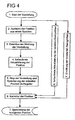
- step 1 becomes the adjustment started by the occupant pressing a button of the actuator presses to move the vehicle seat in a different position.
- an electric motor M1, M2, M3 or M4 is energized by the control device ECU.
- step 2 Before the start of the rotational movement of the electric motor M1, M2, M3 or M4 is as a result of step 2, the previous standstill position read from a memory and loaded into a register of the microcontroller MCU. Following in step 3 the Adjustment direction determined by a control variable of the microcontroller. The tax size can be additionally evaluated as a parameter for later correction.
- each automatically adjustable position corresponds to a count value. Will the adjustment stopped by the button is released, or the adjustment reaches a automatically adjustable, stored for this purpose position, the current Position buffered in a register of the microcontroller MCU.
- steps 2 to 5 will be time variable or by the adjustment movement dependent parameters are continuously updated in the process X.
- time-invariant parameters are determined and stored in a memory, for example cached in a RAM.
- step 6 the in the register of the Microcontroller MCU cached position depending on the Characteristics corrected.
- the corrected position is in a following step 7 in a non-volatile memory stored. The same is corrected for a new adjustment Position in a, not shown in FIG 4 step 4 ', again from the non-volatile Memory read out.
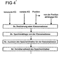
- step 6 of FIG. 4 is shown in detail. From the constant parameters KG, the variable parameters KG and the position, and dependent on the position Characteristics KG in step 6a, one or more class addresses is determined.
- One or more class addresses is in turn a constant or of further conditions, For example, associated with the adjustment of dependent memory content.
- the memory content forms the position error due to the at least temporary asynchronous motion from.
- the content of the errors is identical or a transformed value, which is in a later algorithm in the microcontroller MCU is calculated.
- Step 6b the memory is queried for the corresponding class address and in step 6c, the memory contents for the class address are read out.
- step 6d the correction of the position based on the memory contents, wherein the incoming signals Hall sensors H1, H2, H3 or H4 are weighted accordingly.
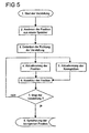
- FIG. 5 shows an alternative method for correcting the position error. Steps 1 to 3 corresponding to the steps 1 to 3 of FIG. 4.
- step 4 the position is changed updated some counts.
- the parameters are updated in step 5.
- step 6 in real time the position value, for example, based on the determined torque requirement of the electric motor M1 to M4, corrected.
- step 7 no end of the adjustment, then in the following steps 4 and 5, the position and the parameters again depending on the previously corrected position updated. If the adjustment is stopped in step 7, the last one is saved corrected position in step 8.
Landscapes
- Engineering & Computer Science (AREA)
- Aviation & Aerospace Engineering (AREA)
- Transportation (AREA)
- Mechanical Engineering (AREA)
- Seats For Vehicles (AREA)
- Control Of Direct Current Motors (AREA)
- Control Of Position Or Direction (AREA)
Description
- die elektrische Antriebsvorrichtung mit dem verstellbaren Teil derart elastisch gekoppelt, dass zumindest temporär eine asynchrone Bewegung zwischen der elektrischen Antriebsvorrichtung und dem verstellbaren Teil auftreten kann,
- und zusätzlich das Drehmoment (MMot) und/oder mindestens eine mit diesem korrelierende Kenngröße der elektrischen Antriebsvorrichtung zur Korrektur eines durch eine asynchrone Bewegung zwischen der elektrischen Antriebsvorrichtung und dem verstellbaren Teil verursachten Positionsfehlers ausgewertet.
- Fig 1
- eine perspektivische Darstellung eines Sitzgestells mit einer Vielzahl motorisch angetriebener Verstellwege,
- Fig 2
- eine Auswertevorrichtung und vier Motoren mit jeweils einem Hallsensor,
- Fig 3
- ein Modell zur Berechnung des von dem Elektromotor abgegeben Drehmomentes,
- Fig 4
- ein schematischer Ablauf eines Korrekturverfahrens,
- Fig 4'
- ein schematisches Detail des Ablaufes des Korrekturverfahrens aus Fig 4, und
- Fig 5
- ein weiterer schematischer Ablauf eines Korrekturverfahrens.
- 1
- Schienenführung
- 9
- flexible Welle
- 10
- untere Führungsschiene
- 11
- obere Führungsschiene
- 17, 19
- Verbindungswelle
- 20, 21
- Antriebshebel
- 22
- Seitenblech, Seitenteil
- 210
- Hebelarm
- 220, 221
- Gurtanschlagspunkt
- 30, 31, 32, 33
- Getriebe
- 40
- Schwenklager
- M1, M2, M3, M4, 61
- Elektromotoren
- H1, H2, H3, H4
- Hallsensoren
- IH
- Auswerteschaltung, Schnittstelle der Hallsensoren
- ECU
- Steuerungsvorrichtung, Auswertevorrichtung, Mikrocontroller
- SU
- Betätigungsvorrichtung, Schalterblock
- I
- Schnittstelle der Betätigungsvorrichtung
- CAN
- CAN-Bus
- CAN-I
- CAN-Bus Schnittstelle
- UB
- Batteriespannung
- GND
- Masse
- PT
- Leistungstransistoren, Leistungsstufe
- PR
- Leistungsrelais', Leistungsschalter
- D
- Treiber
- MCU
- Mikrocontroller
- VS
- Spannungsversorgung der integrierten Schaltkreise
- KG
- Kenngröße
Claims (19)
- Verfahren zur Bestimmung einer Position eines durch eine elektrische Antriebsvorrichtung verstellbaren Teils eines Kraftfahrzeugsitzes durch Auswertung eines in Abhängigkeit einer Antriebsbewegung der elektrischen Antriebsvorrichtung generierten Signals,
dadurch gekennzeichnet, dassdie elektrische Antriebsvorrichtung mit dem verstellbaren Teil derart elastisch gekoppelt ist, dass zumindest temporär eine asynchrone Bewegung zwischen der elektrischen Antriebsvorrichtung und dem verstellbaren Teil auftreten kann,und zusätzlich das Drehmoment (MMot) und/oder mindestens eine mit diesem korrelierende Kenngröße der elektrischen Antriebsvorrichtung zur Korrektur eines durch eine asynchrone Bewegung zwischen der elektrischen Antriebsvorrichtung und dem verstellbaren Teil verursachten Positionsfehlers ausgewertet wird. - Verfahren nach Anspruch 1, dadurch gekennzeichnet, dass die mit dem Drehmoment (MMot) korrelierende Kenngröße der elektrischen Antriebsvorrichtung eine Antriebsspannung (UKlemm), ein Antriebsstrom (IMot) und/oder eine Drehzahl (n) ist.
- Verfahren nach Anspruch 1 oder 2, dadurch gekennzeichnet, dass der Positionsfehler in Abhängigkeit von einer zur Korrektur zugeordneten Klasse korrigiert wird, und die für den Korrekturfall aktuelle Klasse durch einen Vergleich des Drehmoments (MMot) und/oder mindestens einer korrelierenden Kenngröße mit einem oder mehreren Schwellwerten ermittelt wird.
- Verfahren nach Anspruch 3, dadurch gekennzeichnet, dass jeder Klasse ein Korrekturfaktor zur Korrektur des Positionsfehlers zugeordnet wird.
- Verfahren nach einem der Ansprüche 3 oder 4, dadurch gekennzeichnet, dass jeder Klasse eine Korrekturkonstante zur Korrektur des Positionsfehlers zugeordnet wird.
- Verfahren nach einem der vorhergehenden Ansprüche, dadurch gekennzeichnet, dass zur Korrektur das Signal in Abhängigkeit von Drehmoment (MMot) und/oder mindestens einer korrelierenden Kenngröße gewichtet wird.
- Verfahren nach Anspruch 6, dadurch gekennzeichnet, dass zur Gewichtung Daten des Signals in additive Daten und subtraktive Daten unterteilt werden, und die aktuelle Position entsprechend der additiven Daten beziehungsweise subtraktiven Daten in Verstellrichtung beziehungsweise gegen die Verstellrichtung korrigiert wird.
- Verfahren nach Anspruch 6 oder 7, dadurch gekennzeichnet, dass zur Gewichtung Daten des Signals in zu wertende Daten beziehungsweise in zur Korrektur verfallene Daten unterteilt werden, und die Position entsprechend der zu wertenden Daten aktualisiert wird.
- Verfahren nach einem der Ansprüche 6 bis 8, dadurch gekennzeichnet, dass als Signale Impulse ausgewertet werden, die in Abhängigkeit von der Antriebsbewegung, insbesondere eines Rotationswinkels der Antriebsbewegung, generiert werden, zur Auswertung die Impulse gezählt und entsprechend der Verstellrichtung addiert beziehungsweise subtrahiert werden, und zur Korrektur die Zählung der Impulse korrigiert wird.
- Verfahren nach den Ansprüchen 7 und 9, dadurch gekennzeichnet, dass zur Korrekturdie Impulse zu der Position addiert werden, wenn die Antriebsvorrichtung auf Grund eines Steuerungssignals als Kenngröße für die Verstellrichtung bestromt wird, unddie Impulse von der Position subtrahiert werden, wenn die Bestromung Antriebsvorrichtung für die Verstellrichtung beendet wird,die Impulse von der Position subtrahiert werden, wenn die Antriebsvorrichtung auf Grund eines Steuerungssignals als Kenngröße für die Gegen-Verstellrichtung bestromt wird, unddie Impulse von der Position addiert werden, wenn die Bestromung der Antriebsvorrichtung für die Gegen-Verstellrichtung beendet wird.
- Verfahren nach einem der vorhergehenden Ansprüche, dadurch gekennzeichnet, dass zusätzlich eine Antriebsgröße, insbesondereausgewertet wird.ein Steuersignal für die Verstellrichtung,ein Tastverhältnis einer Pulsweitenmodulation,eine Batteriespannung,eine Verstellzeit,eine Antriebstemperatur,ein gemessenes oder berechnetes Drehmoment, odereine Kombination mehrerer Antriebsgrößen der Antriebsvorrichtung
- Verfahren nach einem der vorhergehenden Ansprüche, dadurch gekennzeichnet, dass zusätzlich eine Betriebsgröße, insbesondereausgewertet wird.eine Sitzbelegung,ein Einsitzgewicht (des Sitzbenutzers),eine Verteilung des Einsitzgewichtes,eine Umgebungstemperatur, odereine Kombination mehrerer Betriebsgrößen des Sitzes oder einer oder mehrerer Betriebsgrößen mit einer oder mehrerer Antriebsgrößen
- Verfahren nach einem der vorhergehenden Ansprüche, dadurch gekennzeichnet, dass zusätzlich für die Positionen gespeicherte Schwergängigkeiten des Verstellsystems ausgewertet werden.
- Verfahren nach einem der vorhergehenden Ansprüche, dadurch gekennzeichnet, dass zusätzlich mindestens ein signifikantes Charakteristikum der Verstellung ausgewertet wird.
- Verfahren nach einem der Ansprüche 7 bis 14, dadurch gekennzeichnet, dass eine Kombination aus einer oder mehrerer Betriebsgrößen, einer oder mehrerer Antriebsgrößen, gespeicherten Schwergängigkeiten und/oder eines oder mehrerer signifikanter Charakteristika ausgewertet werden.
- Verfahren nach einem der vorhergehenden Ansprüche, dadurch gekennzeichnet, dass die Antriebsbewegung mittels eines einkanaligen Sensors bestimmt wird, indem als Signal ein nicht-richtungsdetektierbares Sensorsignal des einkanaligen Sensors ausgewertet wird.
- Verfahren nach einem der vorhergehenden Ansprüche, dadurch gekennzeichnet, dass das Drehmoment (MMot) und/oder mindestens eine korrelierende Kenngröße in Doppelfunktion zur Korrektur eines Positionsfehlers und zur Detektion eines Einklemmens eines Gegenstandes oder menschlichen Körperteils ausgewertet wird.
- Vorrichtung zur Bestimmung einer Position eines durch eine elektrische Antriebsvorrichtung verstellbaren Teils eines Kraftfahrzeugsitzes durch Auswertung eines in Abhängigkeit einer Antriebsbewegung der elektrischen Antriebsvorrichtung generierten Signals,
dadurch gekennzeichnet, dassdie elektrische Antriebsvorrichtung mit dem verstellbaren Teil derart elastisch gekoppelt ist, dass zumindest temporär eine asynchrone Bewegung zwischen der elektrischen Antriebsvorrichtung und dem verstellbaren Teil auftreten kann,und zusätzlich das Drehmoment (MMot) und/oder mindestens eine mit diesem korrelierende Kenngröße der elektrischen Antriebsvorrichtung zur Korrektur eines durch eine asynchrone Bewegung zwischen der elektrischen Antriebsvorrichtung und dem verstellbaren Teil verursachten Positionsfehlers ausgewertet wird,wobei Mittel zur Korrektur eines anhand der Auswertung des Drehmoments (MMot) und/oder der korrelierenden Kenngröße (UKlemm, IMot, n) ermittelten Positionsfehlers vorgesehen sind. - Vorrichtung nach Anspruch 18, dadurch gekennzeichnet, dass die mit dem Drehmoment (MMot) korrelierende Kenngröße der elektrischen Antriebsvorrichtung eine Antriebsspannung (UKlemm), ein Antriebsstrom (IMot) und/oder eine Drehzahl (n) ist.
Applications Claiming Priority (3)
| Application Number | Priority Date | Filing Date | Title |
|---|---|---|---|
| DE10122586A DE10122586A1 (de) | 2001-05-10 | 2001-05-10 | Verfahren und Vorrichtung zur Bestimmung einer Position eines durch eine Antriebsvorrichtung verstellbaren Teils eines Kraftfahrzeugsitzes |
| DE10122586 | 2001-05-10 | ||
| PCT/DE2002/001683 WO2002090139A1 (de) | 2001-05-10 | 2002-05-06 | Verfahren und vorrichtung zur bestimmung einer position eines durch eine antriebsvorrichtung verstellbaren teils eines kraftfahrzeugsitzes |
Publications (2)
| Publication Number | Publication Date |
|---|---|
| EP1385716A1 EP1385716A1 (de) | 2004-02-04 |
| EP1385716B1 true EP1385716B1 (de) | 2005-04-06 |
Family
ID=7684199
Family Applications (1)
| Application Number | Title | Priority Date | Filing Date |
|---|---|---|---|
| EP02740330A Expired - Lifetime EP1385716B1 (de) | 2001-05-10 | 2002-05-06 | Verfahren und vorrichtung zur bestimmung einer position eines durch eine antriebsvorrichtung verstellbaren teils eines kraftfahrzeugsitzes |
Country Status (5)
| Country | Link |
|---|---|
| US (1) | US7099761B2 (de) |
| EP (1) | EP1385716B1 (de) |
| DE (2) | DE10122586A1 (de) |
| ES (1) | ES2240755T3 (de) |
| WO (1) | WO2002090139A1 (de) |
Cited By (1)
| Publication number | Priority date | Publication date | Assignee | Title |
|---|---|---|---|---|
| DE102008057861A1 (de) * | 2008-11-18 | 2010-05-20 | Continental Automotive Gmbh | Verfahren zur automatischen Sitzverstellung und dessen Anwendung |
Families Citing this family (13)
| Publication number | Priority date | Publication date | Assignee | Title |
|---|---|---|---|---|
| DE10341130A1 (de) * | 2003-09-06 | 2005-03-31 | Daimlerchrysler Ag | Kindersitz für ein Kraftfahrzeug |
| US7699399B2 (en) * | 2005-08-30 | 2010-04-20 | Aisin Seiki Kabushiki Kaisha | Seat apparatus |
| DE202006002525U1 (de) * | 2006-02-17 | 2007-07-05 | Brose Fahrzeugteile Gmbh & Co. Kommanditgesellschaft, Coburg | Einklemmschutz einer motorisch angetriebenen Verstellvorrichtung für eine Verstellvorrichtung |
| DE202006002527U1 (de) * | 2006-02-17 | 2007-06-28 | Brose Fahrzeugteile Gmbh & Co. Kommanditgesellschaft, Coburg | Einklemmschutz einer motorisch angetriebenen Verstellvorrichtung |
| FR2897682B1 (fr) * | 2006-02-22 | 2008-04-18 | Peugeot Citroen Automobiles Sa | Procede et dispositif pour connaitre avec precision la position d'un siege electrique automobile ou analogue |
| FR2924069B1 (fr) * | 2007-11-23 | 2010-06-04 | Peugeot Citroen Automobiles Sa | Dispositif de controle du deplacement d'un siege electrique de vehicule automobile, pour la detection d'un coincement |
| WO2010083877A1 (de) * | 2009-01-24 | 2010-07-29 | Ebm-Papst St. Georgen Gmbh & Co. Kg | Elektromotor, und vorrichtung zum erzeugen eines signals für die steuerung eines solchen |
| US10234073B2 (en) | 2016-08-24 | 2019-03-19 | Lear Corporation | Modular plastic motor bracket |
| CN106379202A (zh) * | 2016-08-31 | 2017-02-08 | 安徽通宇电子股份有限公司 | 一种智能座椅控制系统 |
| DE102020113982A1 (de) * | 2020-05-25 | 2021-11-25 | Faurecia Autositze Gmbh | Kraftfahrzeugsitz |
| CN117881569A (zh) * | 2021-08-20 | 2024-04-12 | 博泽(班贝格)汽车零部件欧洲两合公司 | 用于调节内部空间组件的驱动设备 |
| DE102022100482A1 (de) | 2022-01-11 | 2023-07-13 | Minebea Mitsumi Inc. | Verfahren zur Bestimmung einer Stellungsänderung eines mit einem Elektromotor mechanisch gekoppelten Bauteils |
| CN118220050A (zh) * | 2023-09-22 | 2024-06-21 | 比亚迪股份有限公司 | 车辆安全带控制方法、装置、电子设备及存储介质 |
Family Cites Families (13)
| Publication number | Priority date | Publication date | Assignee | Title |
|---|---|---|---|---|
| DE3633347A1 (de) * | 1986-10-01 | 1988-04-14 | Daimler Benz Ag | Verstelleinrichtung eines sitzes |
| US4907153A (en) | 1987-08-24 | 1990-03-06 | Brodsky Stephen L | Automobile seat position control system |
| US4922170A (en) * | 1988-01-05 | 1990-05-01 | Kabushiki Kaisha Imasen Denki Seisakusho | Automotive power seat assembly |
| JPH03112385A (ja) * | 1989-09-22 | 1991-05-13 | Tachi S Co Ltd | パワーシートのモータ制御システムおよびモータ制御装置 |
| US5179328A (en) * | 1990-03-16 | 1993-01-12 | Jidosha Denki Kogyo K.K. | Power seat apparatus |
| DE4024905A1 (de) * | 1990-08-06 | 1992-02-13 | Brose Fahrzeugteile | Verfahren und schaltung zum anfahren gespeicherter positionen eines kraftfahrzeugsitzes |
| US6195603B1 (en) * | 1995-08-11 | 2001-02-27 | Lear Corporation | Multiple speed vehicle seat memory control apparatus |
| US6243635B1 (en) | 1997-08-27 | 2001-06-05 | Nartron Corporation | Integrated seat control with adaptive capabilities |
| DE19845772C2 (de) * | 1998-09-22 | 2000-10-19 | Brose Fahrzeugteile | Kraftfahrzeugsitz |
| DE19855996C1 (de) | 1998-10-27 | 1999-12-16 | Daimler Chrysler Ag | Verfahren zur Erkennung der Bewegung, Bewegungsrichtung und der Position eines mittels eines elektrischen Motors bewegbaren Teils sowie geeignete Schaltungsanordnung |
| DE19852541C1 (de) * | 1998-11-05 | 2000-03-23 | Brose Fahrzeugteile | Einrichtung und Verfahren zur Erkennung der Belegung eines Kraftfahrzeugsitzes |
| DE19855004C5 (de) * | 1998-11-20 | 2006-12-28 | Brose Fahrzeugteile Gmbh & Co. Kommanditgesellschaft, Coburg | Antrieb für Verstellvorrichtungen in Kraftfahrzeugen |
| DE29823235U1 (de) * | 1998-12-30 | 1999-04-29 | Trw Repa Gmbh | Fahrzeugsicherheitsvorrichtung zum Schutz der Füße des Insassen |
-
2001
- 2001-05-10 DE DE10122586A patent/DE10122586A1/de not_active Withdrawn
-
2002
- 2002-05-06 US US10/477,011 patent/US7099761B2/en not_active Expired - Fee Related
- 2002-05-06 DE DE50202721T patent/DE50202721D1/de not_active Expired - Lifetime
- 2002-05-06 WO PCT/DE2002/001683 patent/WO2002090139A1/de not_active Ceased
- 2002-05-06 ES ES02740330T patent/ES2240755T3/es not_active Expired - Lifetime
- 2002-05-06 EP EP02740330A patent/EP1385716B1/de not_active Expired - Lifetime
Cited By (2)
| Publication number | Priority date | Publication date | Assignee | Title |
|---|---|---|---|---|
| DE102008057861A1 (de) * | 2008-11-18 | 2010-05-20 | Continental Automotive Gmbh | Verfahren zur automatischen Sitzverstellung und dessen Anwendung |
| DE102008057861B4 (de) * | 2008-11-18 | 2010-09-16 | Continental Automotive Gmbh | Verfahren zur automatischen Sitzverstellung und dessen Anwendung |
Also Published As
| Publication number | Publication date |
|---|---|
| DE50202721D1 (de) | 2005-05-12 |
| EP1385716A1 (de) | 2004-02-04 |
| WO2002090139A1 (de) | 2002-11-14 |
| ES2240755T3 (es) | 2005-10-16 |
| DE10122586A1 (de) | 2002-11-28 |
| US7099761B2 (en) | 2006-08-29 |
| US20040158378A1 (en) | 2004-08-12 |
Similar Documents
| Publication | Publication Date | Title |
|---|---|---|
| DE3689114T2 (de) | Multiplexsteuergerät für die Speicherung von Sitzposition oder dergleichen. | |
| EP2057340B1 (de) | Verstellvorrichtung für ein bewegliches karosserieteil eines kraftfahrzeugs sowie verfahren zur verstellung des beweglichen karosserieteils | |
| EP1385716A1 (de) | Verfahren und vorrichtung zur bestimmung einer position eines durch eine antriebsvorrichtung verstellbaren teils eines kraftfahrzeugsitzes | |
| WO2017137030A9 (de) | Verfahren und vorrichtung zur beaufschlagung einer kraftfahrzeugtür im sinne eines abbremsens insbesondere zur kollisionsvermeidung | |
| EP3247613B1 (de) | Lenksystem für ein automatisiertes fahren eines kraftfahrzeuges | |
| DE102008025247A1 (de) | Steuervorrichtung für eine Schließtafel | |
| DE102009044819A1 (de) | Scheibenwischersystem und Scheibenwischersteuerverfahren | |
| DE10324592A1 (de) | Verfahren und Vorrichtung zur Erfassung eines Einklemmzustands bei einem Öffnungs/Schließelement | |
| DE102016102491A1 (de) | Steuervorrichtung für ein öffnungsfähiges und schließfähiges Glied und Steuerverfahren für ein öffnungsfähiges und schließfähiges Glied | |
| DE102011055329A1 (de) | Antriebssteuervorrichtung und Antriebssteuerverfahren für Stellglieder | |
| WO1999006251A1 (de) | Scheibenwischvorrichtung | |
| DE4034528A1 (de) | Verfahren und vorrichtung zum ueberwachen eines motorbetaetigten sitzes | |
| DE102017128798A1 (de) | Fahrzeug-Elektromotor-Steuervorrichtung und Fahrzeug-Elektromotor-Steuerverfahren | |
| DE102006053080A1 (de) | Wandelement-Steuersystem | |
| WO2024061935A1 (de) | Fahrzeugsitz mit integrierter gewichtserfassung | |
| EP0473068A1 (de) | Anordnung zum Schliessen einzelner motorantreibbarer Fenster eines Fahrzeuges | |
| DE112017000593T5 (de) | Scheibenwischersteuerungsvorrichtung | |
| DE202005019464U1 (de) | Verstelleinrichtung sowie elektronische Baugruppe | |
| DE102006041999B4 (de) | Steuergerät für ein Öffnungs-/Schließ-Element und Verfahren zum Erfassen von Zusammendrücken | |
| DE69937979T2 (de) | Wischeranordnung und Verfahren zum Steuern dieser Anordnung | |
| DE102020113982A1 (de) | Kraftfahrzeugsitz | |
| DE102008007267A1 (de) | Sitzeinsteller | |
| WO2008019645A1 (de) | Verfahren zur abstandsregelung | |
| DE102009001762A1 (de) | Zustandsspeichervorrichtung für ein bewegliches Teil | |
| DE102004053287B4 (de) | Sonnendacheinheit für ein Fahrzeug |
Legal Events
| Date | Code | Title | Description |
|---|---|---|---|
| PUAI | Public reference made under article 153(3) epc to a published international application that has entered the european phase |
Free format text: ORIGINAL CODE: 0009012 |
|
| 17P | Request for examination filed |
Effective date: 20031110 |
|
| AK | Designated contracting states |
Kind code of ref document: A1 Designated state(s): AT BE CH CY DE DK ES FI FR GB GR IE IT LI LU MC NL PT SE TR |
|
| AX | Request for extension of the european patent |
Extension state: AL LT LV MK RO SI |
|
| 17Q | First examination report despatched |
Effective date: 20040622 |
|
| GRAP | Despatch of communication of intention to grant a patent |
Free format text: ORIGINAL CODE: EPIDOSNIGR1 |
|
| RBV | Designated contracting states (corrected) |
Designated state(s): DE ES FR GB IT |
|
| GRAS | Grant fee paid |
Free format text: ORIGINAL CODE: EPIDOSNIGR3 |
|
| GRAA | (expected) grant |
Free format text: ORIGINAL CODE: 0009210 |
|
| AK | Designated contracting states |
Kind code of ref document: B1 Designated state(s): DE ES FR GB IT |
|
| PG25 | Lapsed in a contracting state [announced via postgrant information from national office to epo] |
Ref country code: IT Free format text: LAPSE BECAUSE OF FAILURE TO SUBMIT A TRANSLATION OF THE DESCRIPTION OR TO PAY THE FEE WITHIN THE PRESCRIBED TIME-LIMIT;WARNING: LAPSES OF ITALIAN PATENTS WITH EFFECTIVE DATE BEFORE 2007 MAY HAVE OCCURRED AT ANY TIME BEFORE 2007. THE CORRECT EFFECTIVE DATE MAY BE DIFFERENT FROM THE ONE RECORDED. Effective date: 20050406 |
|
| REG | Reference to a national code |
Ref country code: GB Ref legal event code: FG4D Free format text: NOT ENGLISH |
|
| REF | Corresponds to: |
Ref document number: 50202721 Country of ref document: DE Date of ref document: 20050512 Kind code of ref document: P |
|
| GBT | Gb: translation of ep patent filed (gb section 77(6)(a)/1977) |
Effective date: 20050801 |
|
| REG | Reference to a national code |
Ref country code: ES Ref legal event code: FG2A Ref document number: 2240755 Country of ref document: ES Kind code of ref document: T3 |
|
| PLBE | No opposition filed within time limit |
Free format text: ORIGINAL CODE: 0009261 |
|
| STAA | Information on the status of an ep patent application or granted ep patent |
Free format text: STATUS: NO OPPOSITION FILED WITHIN TIME LIMIT |
|
| ET | Fr: translation filed | ||
| 26N | No opposition filed |
Effective date: 20060110 |
|
| PGFP | Annual fee paid to national office [announced via postgrant information from national office to epo] |
Ref country code: GB Payment date: 20120502 Year of fee payment: 11 Ref country code: FR Payment date: 20120608 Year of fee payment: 11 |
|
| PGFP | Annual fee paid to national office [announced via postgrant information from national office to epo] |
Ref country code: ES Payment date: 20120607 Year of fee payment: 11 |
|
| GBPC | Gb: european patent ceased through non-payment of renewal fee |
Effective date: 20130506 |
|
| REG | Reference to a national code |
Ref country code: FR Ref legal event code: ST Effective date: 20140131 |
|
| PG25 | Lapsed in a contracting state [announced via postgrant information from national office to epo] |
Ref country code: GB Free format text: LAPSE BECAUSE OF NON-PAYMENT OF DUE FEES Effective date: 20130506 |
|
| PG25 | Lapsed in a contracting state [announced via postgrant information from national office to epo] |
Ref country code: FR Free format text: LAPSE BECAUSE OF NON-PAYMENT OF DUE FEES Effective date: 20130531 |
|
| REG | Reference to a national code |
Ref country code: ES Ref legal event code: FD2A Effective date: 20140610 |
|
| PG25 | Lapsed in a contracting state [announced via postgrant information from national office to epo] |
Ref country code: ES Free format text: LAPSE BECAUSE OF NON-PAYMENT OF DUE FEES Effective date: 20130507 |
|
| PGFP | Annual fee paid to national office [announced via postgrant information from national office to epo] |
Ref country code: DE Payment date: 20150531 Year of fee payment: 14 |
|
| REG | Reference to a national code |
Ref country code: DE Ref legal event code: R119 Ref document number: 50202721 Country of ref document: DE |
|
| PG25 | Lapsed in a contracting state [announced via postgrant information from national office to epo] |
Ref country code: DE Free format text: LAPSE BECAUSE OF NON-PAYMENT OF DUE FEES Effective date: 20161201 |