EP1385196A2 - Method of producing a Group III nitride semiconductor crystal - Google Patents
Method of producing a Group III nitride semiconductor crystal Download PDFInfo
- Publication number
- EP1385196A2 EP1385196A2 EP03016327A EP03016327A EP1385196A2 EP 1385196 A2 EP1385196 A2 EP 1385196A2 EP 03016327 A EP03016327 A EP 03016327A EP 03016327 A EP03016327 A EP 03016327A EP 1385196 A2 EP1385196 A2 EP 1385196A2
- Authority
- EP
- European Patent Office
- Prior art keywords
- semiconductor crystal
- crystal
- semiconductor
- producing
- starting substrate
- Prior art date
- Legal status (The legal status is an assumption and is not a legal conclusion. Google has not performed a legal analysis and makes no representation as to the accuracy of the status listed.)
- Withdrawn
Links
Images
Classifications
-
- H—ELECTRICITY
- H10—SEMICONDUCTOR DEVICES; ELECTRIC SOLID-STATE DEVICES NOT OTHERWISE PROVIDED FOR
- H10P—GENERIC PROCESSES OR APPARATUS FOR THE MANUFACTURE OR TREATMENT OF DEVICES COVERED BY CLASS H10
- H10P95/00—Generic processes or apparatus for manufacture or treatments not covered by the other groups of this subclass
- H10P95/90—Thermal treatments, e.g. annealing or sintering
-
- C—CHEMISTRY; METALLURGY
- C30—CRYSTAL GROWTH
- C30B—SINGLE-CRYSTAL GROWTH; UNIDIRECTIONAL SOLIDIFICATION OF EUTECTIC MATERIAL OR UNIDIRECTIONAL DEMIXING OF EUTECTOID MATERIAL; REFINING BY ZONE-MELTING OF MATERIAL; PRODUCTION OF A HOMOGENEOUS POLYCRYSTALLINE MATERIAL WITH DEFINED STRUCTURE; SINGLE CRYSTALS OR HOMOGENEOUS POLYCRYSTALLINE MATERIAL WITH DEFINED STRUCTURE; AFTER-TREATMENT OF SINGLE CRYSTALS OR A HOMOGENEOUS POLYCRYSTALLINE MATERIAL WITH DEFINED STRUCTURE; APPARATUS THEREFOR
- C30B29/00—Single crystals or homogeneous polycrystalline material with defined structure characterised by the material or by their shape
- C30B29/10—Inorganic compounds or compositions
- C30B29/40—AIIIBV compounds wherein A is B, Al, Ga, In or Tl and B is N, P, As, Sb or Bi
- C30B29/403—AIII-nitrides
- C30B29/406—Gallium nitride
-
- C—CHEMISTRY; METALLURGY
- C30—CRYSTAL GROWTH
- C30B—SINGLE-CRYSTAL GROWTH; UNIDIRECTIONAL SOLIDIFICATION OF EUTECTIC MATERIAL OR UNIDIRECTIONAL DEMIXING OF EUTECTOID MATERIAL; REFINING BY ZONE-MELTING OF MATERIAL; PRODUCTION OF A HOMOGENEOUS POLYCRYSTALLINE MATERIAL WITH DEFINED STRUCTURE; SINGLE CRYSTALS OR HOMOGENEOUS POLYCRYSTALLINE MATERIAL WITH DEFINED STRUCTURE; AFTER-TREATMENT OF SINGLE CRYSTALS OR A HOMOGENEOUS POLYCRYSTALLINE MATERIAL WITH DEFINED STRUCTURE; APPARATUS THEREFOR
- C30B25/00—Single-crystal growth by chemical reaction of reactive gases, e.g. chemical vapour-deposition growth
- C30B25/02—Epitaxial-layer growth
- C30B25/18—Epitaxial-layer growth characterised by the substrate
-
- C—CHEMISTRY; METALLURGY
- C30—CRYSTAL GROWTH
- C30B—SINGLE-CRYSTAL GROWTH; UNIDIRECTIONAL SOLIDIFICATION OF EUTECTIC MATERIAL OR UNIDIRECTIONAL DEMIXING OF EUTECTOID MATERIAL; REFINING BY ZONE-MELTING OF MATERIAL; PRODUCTION OF A HOMOGENEOUS POLYCRYSTALLINE MATERIAL WITH DEFINED STRUCTURE; SINGLE CRYSTALS OR HOMOGENEOUS POLYCRYSTALLINE MATERIAL WITH DEFINED STRUCTURE; AFTER-TREATMENT OF SINGLE CRYSTALS OR A HOMOGENEOUS POLYCRYSTALLINE MATERIAL WITH DEFINED STRUCTURE; APPARATUS THEREFOR
- C30B29/00—Single crystals or homogeneous polycrystalline material with defined structure characterised by the material or by their shape
- C30B29/10—Inorganic compounds or compositions
- C30B29/40—AIIIBV compounds wherein A is B, Al, Ga, In or Tl and B is N, P, As, Sb or Bi
- C30B29/403—AIII-nitrides
-
- H—ELECTRICITY
- H10—SEMICONDUCTOR DEVICES; ELECTRIC SOLID-STATE DEVICES NOT OTHERWISE PROVIDED FOR
- H10P—GENERIC PROCESSES OR APPARATUS FOR THE MANUFACTURE OR TREATMENT OF DEVICES COVERED BY CLASS H10
- H10P14/00—Formation of materials, e.g. in the shape of layers or pillars
- H10P14/20—Formation of materials, e.g. in the shape of layers or pillars of semiconductor materials
- H10P14/24—Formation of materials, e.g. in the shape of layers or pillars of semiconductor materials using chemical vapour deposition [CVD]
-
- H—ELECTRICITY
- H10—SEMICONDUCTOR DEVICES; ELECTRIC SOLID-STATE DEVICES NOT OTHERWISE PROVIDED FOR
- H10P—GENERIC PROCESSES OR APPARATUS FOR THE MANUFACTURE OR TREATMENT OF DEVICES COVERED BY CLASS H10
- H10P14/00—Formation of materials, e.g. in the shape of layers or pillars
- H10P14/20—Formation of materials, e.g. in the shape of layers or pillars of semiconductor materials
- H10P14/27—Formation of materials, e.g. in the shape of layers or pillars of semiconductor materials using selective deposition, e.g. simultaneous growth of monocrystalline and non-monocrystalline semiconductor materials
- H10P14/271—Formation of materials, e.g. in the shape of layers or pillars of semiconductor materials using selective deposition, e.g. simultaneous growth of monocrystalline and non-monocrystalline semiconductor materials characterised by the preparation of substrate for selective deposition
-
- H—ELECTRICITY
- H10—SEMICONDUCTOR DEVICES; ELECTRIC SOLID-STATE DEVICES NOT OTHERWISE PROVIDED FOR
- H10P—GENERIC PROCESSES OR APPARATUS FOR THE MANUFACTURE OR TREATMENT OF DEVICES COVERED BY CLASS H10
- H10P14/00—Formation of materials, e.g. in the shape of layers or pillars
- H10P14/20—Formation of materials, e.g. in the shape of layers or pillars of semiconductor materials
- H10P14/27—Formation of materials, e.g. in the shape of layers or pillars of semiconductor materials using selective deposition, e.g. simultaneous growth of monocrystalline and non-monocrystalline semiconductor materials
- H10P14/276—Lateral overgrowth
- H10P14/278—Pendeoepitaxy
-
- H—ELECTRICITY
- H10—SEMICONDUCTOR DEVICES; ELECTRIC SOLID-STATE DEVICES NOT OTHERWISE PROVIDED FOR
- H10P—GENERIC PROCESSES OR APPARATUS FOR THE MANUFACTURE OR TREATMENT OF DEVICES COVERED BY CLASS H10
- H10P14/00—Formation of materials, e.g. in the shape of layers or pillars
- H10P14/20—Formation of materials, e.g. in the shape of layers or pillars of semiconductor materials
- H10P14/29—Formation of materials, e.g. in the shape of layers or pillars of semiconductor materials characterised by the substrates
- H10P14/2901—Materials
- H10P14/2921—Materials being crystalline insulating materials
-
- H—ELECTRICITY
- H10—SEMICONDUCTOR DEVICES; ELECTRIC SOLID-STATE DEVICES NOT OTHERWISE PROVIDED FOR
- H10P—GENERIC PROCESSES OR APPARATUS FOR THE MANUFACTURE OR TREATMENT OF DEVICES COVERED BY CLASS H10
- H10P14/00—Formation of materials, e.g. in the shape of layers or pillars
- H10P14/20—Formation of materials, e.g. in the shape of layers or pillars of semiconductor materials
- H10P14/32—Formation of materials, e.g. in the shape of layers or pillars of semiconductor materials characterised by intermediate layers between substrates and deposited layers
- H10P14/3202—Materials thereof
- H10P14/3214—Materials thereof being Group IIIA-VA semiconductors
- H10P14/3216—Nitrides
-
- H—ELECTRICITY
- H10—SEMICONDUCTOR DEVICES; ELECTRIC SOLID-STATE DEVICES NOT OTHERWISE PROVIDED FOR
- H10P—GENERIC PROCESSES OR APPARATUS FOR THE MANUFACTURE OR TREATMENT OF DEVICES COVERED BY CLASS H10
- H10P14/00—Formation of materials, e.g. in the shape of layers or pillars
- H10P14/20—Formation of materials, e.g. in the shape of layers or pillars of semiconductor materials
- H10P14/32—Formation of materials, e.g. in the shape of layers or pillars of semiconductor materials characterised by intermediate layers between substrates and deposited layers
- H10P14/3242—Structure
- H10P14/3244—Layer structure
- H10P14/3248—Layer structure consisting of two layers
-
- H—ELECTRICITY
- H10—SEMICONDUCTOR DEVICES; ELECTRIC SOLID-STATE DEVICES NOT OTHERWISE PROVIDED FOR
- H10P—GENERIC PROCESSES OR APPARATUS FOR THE MANUFACTURE OR TREATMENT OF DEVICES COVERED BY CLASS H10
- H10P14/00—Formation of materials, e.g. in the shape of layers or pillars
- H10P14/20—Formation of materials, e.g. in the shape of layers or pillars of semiconductor materials
- H10P14/34—Deposited materials, e.g. layers
- H10P14/3402—Deposited materials, e.g. layers characterised by the chemical composition
- H10P14/3414—Deposited materials, e.g. layers characterised by the chemical composition being group IIIA-VIA materials
- H10P14/3416—Nitrides
Definitions
- the present invention relates to a method for obtaining. a good-quality semiconductor crystal independent of a starting substrate by growing a semiconductor crystal of a Group III nitride compound semiconductor on the starting substrate.
- the invention can be applied to production of a crystal growth substrate for various kinds of semiconductor elements. such as an LED.
- the target single crystal e.g., GaN
- the starting substrate e.g., sapphire
- the Group III nitride compound semiconductor is applied to the target single crystal (e.g., GaN) at the time of cooling or the like after the completion of the crystal growing step.
- the problem is as follows.
- a crystal of a nitride semiconductor such as gallium nitride (GaN) is grown on a starting substrate made of sapphire, silicon (Si) or the like and then cooled to the ordinary temperature, a large number of dislocations and cracks occur in the nitride semiconductor layer because of stress caused by the difference in thermal expansion coefficient or lattice constant.
- the invention is developed to solve the problem and an object of the invention is to obtain a good-quality semiconductor crystal independent of a starting substrate.
- a method of producing a semiconductor crystal of a Group III nitride compound semiconductor and independent of a starting substrate comprising:
- a method of producing a semiconductor crystal as a good-quality semiconductor crystal A independent of a starting substrate by growing a semiconductor crystal of a Group III nitride compound semiconductor on the starting substrate including: the seed laminating step of laminating a seed monolayer or multilayer on the starting substrate; the non-etched portion forming step of chemically or physically etching part of a seed layer-forming surface of the starting substrate to thereby partially or dispersively leave the seed layer as non-etched portions on the starting substrate; the crystal growing step of growing the semiconductor crystal A on exposed surfaces of the non-etched portions of the seed layer as initial crystal growth surfaces for starting growth of the semiconductor crystal A until the crystal growth surfaces are connected to one another by crystal growth so as to be provided as at least one series of approximately flat surfaces; and the separating step of breaking the non-etched portions to thereby separate the.semiconductor crystal A from the starting substrate; wherein the crystal growing step is performed by a halide vapor phase epitaxy method in
- Group III nitride compound semi conductor used herein generally includes a semiconductor of any mixed crystal ratio represented by the general formula "Al 1-x-y Ga y In x N; 0 ⁇ x ⁇ 1, 0 ⁇ y ⁇ 1, 0 ⁇ 1-x-y ⁇ 1" which includes binary compounds, ternary compounds, and quaternary compounds.
- a semiconductor containing p-type or n-type impurities as additives also belongs to the category of "Group III nitride compound semiconductor” in this specification.
- a semiconductor in which at least part of the Group III elements (such as Al, Ga, and In) are replaced by boron (B), thallium (Tl), etc.
- Group III nitride compound semiconductor phosphorus
- P arsenic
- As arsenic
- Sb antimony
- Bi bismuth
- Mg magnesium
- Ca calcium
- Si silicon
- Si sulfur
- S selenium
- Te tellurium
- germanium germanium
- Two or more elements may be added simultaneously as these impurities or the two types (p-type and n-type) of impurities may be added simultaneously.
- Examples of the material of the starting substrate include sapphire, spinel, manganese oxide, gallium lithium oxide (LiGaO 2 ), molybdenum sulfide (MoS), silicon(Si), silicon carbide (SiC), AlN, GaAs, InP, GaP, MgO, ZnO, and MgAl 2 O 4 . That is, known or optional crystal growth substrates useful for crystal growth of Group III nitride compound semiconductor can be used as these starting substrate materials.
- a target semiconductor crystal A of a Group III nitride compound semiconductor is grown on a starting substrate having a large number of non-etched portions, the starting substrate and the semiconductor crystal A are connected to each other by only the non-etched portions. For this reason, if the thickness of the semiconductor crystal A is made sufficiently large, internal or external stress can be easily concentrated to act on the non-etched portions. As a result, particularly the stress acts as shear stress on the non-etched portions, so that the non-etched portions are broken when the stress becomes high.
- the starting substrate and the semiconductor crystal A can be easily separated (peeled) from each other.
- the single crystal (semiconductor crystal A) independent of the starting substrate can be obtained by this means.
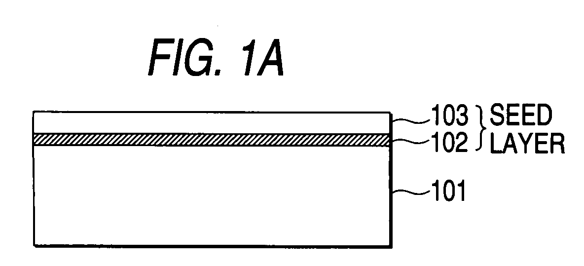
- the "large number of non-etched portions” means that the number of non-etched portions is "large” when at least viewed from a vertical section as shown in Fig. 1B.
- the large number of non-etched portions may be united into one in plan view. Accordingly, even in the case where the large number of non-etched portions are shaped like rectangular waves or precipitous sine waves one-dimensionally united into one or formed as spirally striped non-etched portions in plan view, the function and effect of the invention can be obtained.
- non-etched portions are formed as islands or dots of any other plan shape such as a nearly circular shape, a nearly elliptic shape, a nearly polygonal shape or a nearly regular polygonal shape than the striped shape, it is a matter of course that the function and effect of the invention can be obtained.
- part of the semiconductor crystal A may be left on the starting substrate side, or part (e.g., the broken rest of the non-etched portions) of the starting substrate may be left on the semiconductor crystal A side. That is, the separating step is not performed on the assumption (necessary condition) that the respective materials are separated so completely that the remains of part of these materials are not left.
- V/III ratio means the supply ratio of a Group V material to a Group III material. When the V/III ratio is 30, 1 mol of Group III atoms are supplied while 30 mol of Group V atoms are supplied.
- the V/III ratio is selected to be preferably in a range of from 30 to 80, both inclusively, more preferably in a range of from 40 to 70, both inclusively, further preferably in a range of from 50 to 60, both inclusively. If the V/III ratio is lower than 30, a large number of cracks occur. It is conceived that the reason is that stress is hardly concentrated during epitaxial growth as well as the mechanical strength of the semiconductor crystal A varies because vacancies of Group V, that is, mainly of nitrogen are generated in the semi conductor crystal A on the basis of shortage of supply of Group V, that is, mainly of nitrogen.
- the amount of Group V, that is, mainly of nitrogen becomes so excessive that the growth of the semiconductor crystal A becomes slow because a waste of the Group V material, that is, mainly of the nitrogen material occurs as well as appropriate lateral and vertical epitaxial growth is not obtained.
- the thickness of the semiconductor crystal A in the crystal growing step in the first means is not smaller than 50 ⁇ m.
- the thickness of the target semiconductor crystal A subjected to crystal growth is preferably selected to be not smaller than about 50 ⁇ m.
- the semiconductor crystal A can be strengthened and the shear stress can be concentrated onto the non-etched portions more easily. Because the peeling phenomenon can be generated on the basis of the difference in lattice constant by these functions even in a high-temperature state during the crystal growth, stress caused by the difference in thermal expansion coefficient little acts on the semiconductor crystal A after peeling. Accordingly, dislocations and cracks can be prevented, so that a high-quality semiconductor crystal: A .(e.g., GaN single crystal) can be obtained. More preferably, the thickness of the semiconductor crystal A is selected to be not smaller than 70 ⁇ m.
- the semi conductor crystal A and the starting substrate are cooled or heated to generate stress based on the difference between the thermal expansion coefficient of the semiconductor crystal A and the thermal expansion coefficient of the starting substrate to break the non-etched portions by the stress. That is, the breaking (peeling) may be performed by stress (shear stress) based on the difference between the thermal expansion coefficient of the semiconductor crystal A and the thermal expansion coefficient of the starting substrate.
- the semiconductor crystal A is formed to have a thickness of not smaller than 50 ⁇ m, the semiconductor crystal A and the starting substrate can be separated from each other surely while the crystallinity of the semiconductor crystal A is kept high.
- the seed monolayer or the uppermost layer of the seed multilayer is made of gallium nitride (GaN).
- GaN gallium nitride
- the crystal growth of the target semiconductor crystal A GaN single crystal
- AlGaN, AlGaInN or the like may be selected as a more specific composition of the semiconductor crystal A because it is a matter of course that the value of AlGaN, AlGaInN or the like in industrial use is high.
- the seed monolayer or the uppermost layer of the seed multilayer is preferably made of. a semiconductor (Group III nitride compound semiconductor) relatively near or substantially equal in composition to the target single crystal (semiconductor crystal layer A).
- the seed monolayer or the lowermost layer of the seed multilayer is made of aluminum nitride (AlN). Accordingly, because a so-called buffer layer can be made of aluminum nitride (AlN), a known function based on lamination of the buffer layer (AlN) can be obtained. That is, a known functional theory that stress caused by the difference in lattice constant and acting on the target semiconductor crystal layer A can be relaxed makes it easy or possible to improve the crystallinity of the target semiconductor crystal layer A.
- the multilayer structure of the seed layer is very effective in obtaining the aforementioned function and effect sufficiently.
- the seed layer may be formed from two layers including an AlN buffer layer (first seed layer) as its lower layer, and a GaN layer (second seed layer) as its upper layer. According to this combination, the functions and effects of the fourth and fifth means can be obtained simultaneously.
- the interval for arrangement of the non-etched portions in the non-etched portion forming step is selected to be in a range of from 1 ⁇ m to 50 ⁇ m, both inclusively. More preferably, the interval for arrangement of the non-etched portions is selected to be in a range of from about 5 ⁇ m to about 30 ⁇ m though it depends on the condition for carrying out crystal growth.
- the term "interval for arrangement" means the distance between centers of adjacent ones of the non-etched portions.
- trough portions between the non-etched portions can be covered with the semiconductor crystal A. If the interval is too large, the trough portions between the non-etched portions cannot be surely covered with the semiconductor crystal A so that good-quality crystal (semiconductor-crystal A) of uniform crystallinity cannot be obtained. If the interval is further too large, displacement in crystal orientation becomes remarkable, undesirably.
- the value of S/L is preferably selected to be in a range of from about 1/4 to about 1/6.
- ELO epitaxially lateral growth
- each region between the facing side walls that is, each region including an etched concave portion and its upper portion
- wing may be hereinafter referred to as "seed width”.
- the ratio S/W of the seed width to the wing width is preferably selected to be in a range of from about 1/3 to about 1/5.
- the etching is performed so that the non-etched portions are arranged at approximately regular intervals or at approximately fixed periods.
- the growth condition for lateral growth becomes approximately uniform as a whole, so that the crystallinity or grown film thickness can be prevented from becoming uneven.
- accurate, early, and unique decision of the timing for changing the crystal growth method can be made easily when the crystal growth method is changed partway from a crystal growth method slow in crystal growth rate to a crystal growth method high in crystal growth rate.
- the shear stress can be divided into the non-etched portions approximately equally. Accordingly, all the non-etched portions are broken evenly, so that the starting substrate and the semiconductor crystal A can be separated from each other surely.
- the non-etched portions may be formed as striped mesa portions so that the striped mesa portions are arranged isotropically at regular intervals.
- the formation of such non-etched portions has a merit that it can be performed easily and surely in view of the present situation of the level of existing general etching technology.
- the direction of mesa (non-etched portions) may be preferably ⁇ 1-100> or ⁇ 11-20> of semiconductor crystal.
- a method in which the non-etched portions are formed on lattice points of a two-dimensional triangular lattice based on nearly equilateral triangles 0.1 ⁇ m or more on a side is also effective. According to this method, the area of contact with the starting substrate can be reduced, so that the starting substrate can be separated easily as well as the number of dislocations can be reduced surely on the basis of the aforementioned function.
- a method in which the lateral sectional shape of each non-etched portion is formed into a nearly equilateral triangle, a nearly regular hexagon, nearly a circle, or a quadrangle is also effective.
- the directions of crystal axes of portions of the crystal formed of the Group III nitride compound semiconductor are apt to be equal or the lateral length (thickness) of the non-etched portions can be limited to be substantially uniform with respect to any lateral direction.
- the number of dislocations can be suppressed.
- a regular hexagon or an equilateral triangle may be more preferably selected because the shape of the regular hexagon or the equilateral triangle can be easily matched with the crystal structure of the semiconductor crystal.
- a circle or a quadrangle has a merit that the shape of the circle or the quadrangle can be formed easily from the point of view of manufacturing technique in view of the present situation of the level of existing general etching technology.
- the starting substrate is etched by 0.01 ⁇ m or deeper.
- stress stress
- the lateral thickness, width or diameter of each of the non-etched portions in the non-etched portion forming step is selected to be in a range of from 0.1 ⁇ m to 20 ⁇ m, both inclusively. More preferably, the lateral thickness, width or diameter of each of the non-etched portions is selected to be in a range of from about 0.5 ⁇ m to about 10 ⁇ m though it depends on the condition for carrying out the crystal growth. If the thickness is too large, the influence of stress acting on the semi conductor crystal A becomes large on the basis of the difference in lattice constant so that the number of dislocations in the semiconductor crystal A is apt to increase. If the thickness is too small, the non-etched portions per se can be hardly formed or the crystal growth rate b of the top portions of the non-etched portions becomes low, undesirably.
- the non-etched portions cannot be broken surely, undesirably, because the area of contact with the starting substrate becomes large.
- the influence of stress acting on the semiconductor crystal A on the basis of the difference in lattice constant depends not only on the lateral thickness (length) of each of the non-etched portions but also on the interval for arrangement of the non-etched.portions. If these setting ranges are unsuitable, the influence of stress based on the difference in lattice constant becomes so large that the number of dislocations in the semiconductor crystal A is apt to increase undesirably.
- the shape of the top surface, the bottom surface or the lateral section of each of the non-etched portions may be formed as an at least locally closed shape (island shape).
- the shape may be formed as an outward convexly closed shape.
- the shape of the top surface, the bottom surface or the lateral section of each of the non-etched portions may be formed as nearly a circle or a nearly regular polygon.
- the rest removing step of removing the broken rest of the non-etched portions remaining on a rear surface of the semiconductor crystal A by a chemical or physical process such as etching at least after the separating step.
- the electrode when the electrode is also used as a reflecting mirror for a semiconductor light-emitting element or the like, absorption or scattering of light is reduced near the mirror surface because the broken rest of the non-etched portions is removed. As a result, reflectance is improved, so that light-emitting intensity is improved.
- the rest removing step is performed by a physical process such as polishing, up to the buffer layer on the rear surface of the semiconductor crystal A can be removed or the flatness of the rear surface of the semiconductor crystal A can be improved. Accordingly, the function and effect such as suppression of electric current irregularity and electric resistance or reduction in absorption or scattering of light near the mirror surface can be strengthened more greatly.
- the process may be a heating process.
- the unnecessary portions can be also removed by a heating process or by laser irradiation.
- a Group III nitride compound semiconductor light-emitting element in which a semiconductor crystal produced by a semiconductor crystal producing method according to any one of the first to ninth means is used as a crystal growth substrate. According to this means, it is possible or easy to produce a Group III nitride compound semiconductor light-emitting element from a semiconductor good in crystallinity and low in internal stress.
- a Group. III nitride compound semiconductor light-emitting element produced by crystal growth in which a semiconductor crystal produced by a semiconductor crystal producing method according to any one of the first to ninth means is used as a crystal growth substrate. According to this means, it is possible or easy to produce a Group III nitride compound semiconductor light-emitting element from a semiconductor good in crystallinity and low in internal stress.
- a buffer layer of "Al x Ga 1-x N (0 ⁇ x ⁇ 1)" is preferably formed as the first laminated semiconductor layer.
- an intermediate layer provided separately from the buffer layer and having substantially the same composition (e.g., AlN or AlGaN) as the buffer layer may be laminated periodically or alternately with the other layer or so as to form a multilayer structure.
- the starting substrate and the semi conductor crystal A are cooled in the separating step
- the separating step can be performed surely while the crystallinity of the semiconductor crystal A is kept stable and good.
- the problem can be solved effectively or reasonably.
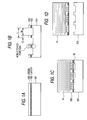
- a seed layer (Group III nitride compound semiconductor) as a laminate of a first seed layer (AlN buffer layer 102) and a second seed layer (GaN layer 103) was formed by vapor phase growth according to a metal organic vapor phase epitaxy method (hereinafter referred to as "MOVPE”) .
- the gases used in the vapor phase growth were ammonia (NH 3 ), carrier gas (H 2 or N 2 ), trimethyl gallium (Ga(CH 3 ) 3 , hereinafter referred to as "TMG”), and trimethyl aluminum (Al(CH 3 ) 3 , hereinafter referred to as "TMA").
- Figs. 1A to 1D are typical sectional views of a semiconductor crystal for explaining a process for producing a semiconductor crystal according to this embodiment.
- a sapphire substrate 101 starting substrate
- a face a of the single-crystal starting substrate 101 was used as a crystal growth surface
- 10 l/min of H 2 , 5 l/min of NH 3 and 20 ⁇ mol/min of TMA were supplied for performing crystal growth to obtain an AlN buffer layer 102 (first seed layer) about 200 nm thick.
- the temperature used for the crystal growth in this case was about 400°C.
- the sapphire substrate 101 was further heated to 1000°C. In this condition, 20 l/min of H 2 , 10 l/min of NH 3 and 300 ⁇ mol/min of TMG were introduced for forming a GaN layer 103 (second seed layer) about 1.5 ⁇ m thick (Fig. 1A).
- a hard-bake resist mask was used so that striped non-etched portions arranged at intervals of L ⁇ 20 ⁇ m were formedby selective dry etching using reactive ion etching (RIE) (Fig. 1B). That is, the substrate was etched by about 0.1 ⁇ m depth in the form of stripes with a stripe width (seed width S) of about 5 ⁇ m and a wing width W of about 15 ⁇ m to thereby form non-etched portions each substantially shaped like a rectangle in sectional.
- the resist mask was formed so that the side wall of each of the striped non-etched portions would be provided as a ⁇ 11-20 ⁇ face of the GaN layer 103 (second seed layer).
- the striped non-etched portions were formed substantially periodically so that the seed layer being a laminate of the GaN layer 103 (second seed layer) and the A1N buffer layer 102 (first seed layer) was provided as a flat top portion of each of the striped non-etched portions.
- the sapphire substrate 101 was exposed in trough portions of wings.
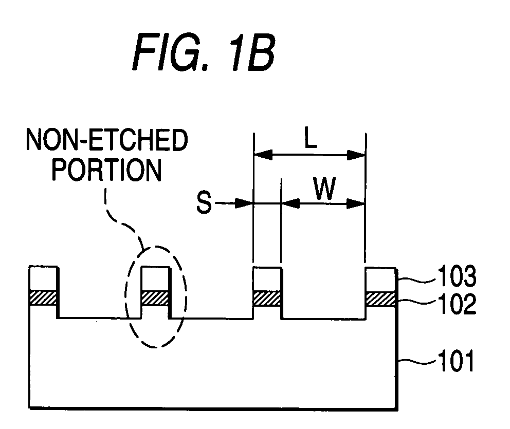
- the target semiconductor crystal A was finally grown to have a thickness of about 250 ⁇ m.
- GaN was grown both laterally-and vertically. After respective GaN crystal portions were once connected so as to be flattened to a series of nearly flat surfaces, the GaN crystal was grown vertically.
- a lateral HVPE apparatus was used in the HVPE method. Ammonia (NH 3 ) was used as a Group V material. GaCl prepared by reaction of Ga and HCl was used as a Group III material.
- the target semiconductor crystal A GaN single crystal
- the reference sign R designates a "cavity”.
- the thickness of GaN exceeds 250 ⁇ m
- peeling is observed near the AlN buffer layer 102 (first seed layer) in the crystal growing step. The peeling is caused by the difference between lattice constants. Accordingly, the following separating step can be omitted. In this case, because peeling can be performed at a high temperature, defects can be prevented from being caused by the difference between thermal expansion coefficients at the time of cooling.
- the semiconductor crystal A was cooled slowly from 1100°C to approximately the room temperature at a cooling rate of 1.5°C/min. As a result, peeling occurred near the AlN buffer layer 102 (first seed layer) , so that the semiconductor crystal A (GaN single crystal) having a required thickness was obtained independent of the starting substrate 101 (Fig. 1D).
- Supply amounts were 50 sccm (standard cubic centimeters) of HCl, 1500 sccm of NH 3 and 5500 sccm of carrier gas.
- the upper surface of the semiconductor crystal A was substantially a mirror surface but a small number of cracks were observed.
- Supply amounts were 50 sccm (standard cubic centimeters) of HCl, 2000 sccm of NH 3 and 5000 sccm of carrier gas.
- the upper surface of the semiconductor crystal A was substantially a mirror surface and there was no crack observed.
- Supply amounts were 50 sccm (standard cubic centimeters) of HCl, 2500 sccm of NH 3 and 4500 sccm of carrier gas.
- the upper surface of the semiconductor crystal A was substantially a mirror surface and there was no crack observed.
- an intermediate layer provided separately from the buffer layer and having substantially the same composition (e.g., AlN or AlGaN) as that of the buffer layer may be laminated periodically or alternately with the other layer or so as to form a multilayer structure.
- the buffer layer or the intermediate layer
- stress caused by the difference in lattice constant and acting on the semiconductor crystal A can be relaxed. That is, crystallinity can be improved on the basis of the same functional theory as in the related art.
- the starting substrate and the semiconductor.crystal A are cooled in the separating step, there may be also used a method in which the starting substrate and the semiconductor crystal A are cooled to approximately the ordinary temperature at a cooling rate of "from -100°C/min to -0.5°C/min" approximately in the condition that the starting substrate and the semiconductor crystal A are left in a reaction chamber of a growth apparatus while an approximately fixed flow rate of ammonia (NH 3 ) gas is imported into the reaction chamber. If the cooling rate is too high, there is fear that breaks or cracks may occur in the semiconductor crystal A.
Landscapes
- Chemical & Material Sciences (AREA)
- Engineering & Computer Science (AREA)
- Crystallography & Structural Chemistry (AREA)
- Materials Engineering (AREA)
- Metallurgy (AREA)
- Organic Chemistry (AREA)
- Inorganic Chemistry (AREA)
- Chemical Kinetics & Catalysis (AREA)
- General Chemical & Material Sciences (AREA)
- Crystals, And After-Treatments Of Crystals (AREA)
- Led Devices (AREA)
Abstract
Description
Claims (11)
- A method of producing a semiconductor crystal of a Group III nitride compound semiconductor and independent of a starting substrate, said method comprising:laminating a seedmonolayer or multilayer on said starting substrate;chemically or physically etching part of a seed layer-forming surface of said starting substrate to thereby partially or dispersively leave said seed Layer as non-etched portions on said starting substrate;growing said semiconductor crystal on exposed surfaces of said non-etched portions of said seed layer as initial crystal growth surfaces for starting growth of said semiconductor crystal until said crystal growth surfaces are connected to one another by crystal growth so as to be provided as at least one series of approximately flat surfaces; andbreaking said non-etched portions to thereby separate said semiconductor crystal from said starting substrate;wherein the crystal growing step is performed by a halide vapor phase epitaxy method in the condition that supply ratio of a Group V material to a Group III material is in a range of from 30 to 80, both inclusively.
- A method of producing a semiconductor crystal according to claim 1, wherein a thickness of said semiconductor crystal in the crystal growing step is not smaller than 50 µm.
- A method of producing a semiconductor crystal according to claim 1, wherein said semiconductor crystal and said starting substrate are cooled or heated to generate stress based on a difference between a thermal expansion coefficient of said semiconductor crystal and a thermal expansion coefficient of said starting substrate to break said non-etched portions by said stress.
- A method of producing a semiconductor crystal according to claim 1, wherein said seed monolayer or an uppermost layer of said seed multilayer is made of gallium nitride (GaN) .
- A method of producing a semiconductor crystal according to claim 1, wherein said seed monolayer or a lowermost layer of said seed multilayer is made of aluminum nitride (AlN) .
- A method of producing a semiconductor crystal according to claim 1, wherein an interval for arrangement of said non-etched portions in the non-etched portion forming step is selected to be in a range of from 1 µm to 50 µm, both inclusively.
- A method of producing a semiconductor crystal according to claim 1, wherein said starting substrate is etched by 0.01 µm or deeper in the non-etched portion forming step.
- A method of producing a semiconductor crystal according to claim 1, wherein a lateral thickness, width or diameter of each of said non-etched portions in the non-etched portion forming step is selected to be in a range of from 0.1 µm to 20 µm, both inclusively.
- A method of producing a semiconductor crystal according to claim 1, further comprising the rest removing step of removing the broken rest of said non-etched portions remaining on a rear surface of said semiconductor.crystal by a chemical or physical process such as etching at least after the separating step.
- A Group III nitride compound semiconductor light-emitting element in which a semiconductor crystal produced by a semiconductor crystal producing method according to claim 1 is used as a crystal growth substrate.
- A Group III nitride compound semiconductor light-emitting element produced by crystal growth in which a semiconductor crystal A produced by a semiconductor crystal producing method according to claim 1 is used as a crystal growth substrate.
Applications Claiming Priority (2)
| Application Number | Priority Date | Filing Date | Title |
|---|---|---|---|
| JP2002210806A JP4201541B2 (en) | 2002-07-19 | 2002-07-19 | Semiconductor crystal manufacturing method and group III nitride compound semiconductor light emitting device manufacturing method |
| JP2002210806 | 2002-07-19 |
Publications (2)
| Publication Number | Publication Date |
|---|---|
| EP1385196A2 true EP1385196A2 (en) | 2004-01-28 |
| EP1385196A3 EP1385196A3 (en) | 2006-10-25 |
Family
ID=29997193
Family Applications (1)
| Application Number | Title | Priority Date | Filing Date |
|---|---|---|---|
| EP03016327A Withdrawn EP1385196A3 (en) | 2002-07-19 | 2003-07-18 | Method of producing a Group III nitride semiconductor crystal |
Country Status (5)
| Country | Link |
|---|---|
| US (1) | US6964705B2 (en) |
| EP (1) | EP1385196A3 (en) |
| JP (1) | JP4201541B2 (en) |
| KR (1) | KR20040010271A (en) |
| TW (1) | TWI233217B (en) |
Cited By (18)
| Publication number | Priority date | Publication date | Assignee | Title |
|---|---|---|---|---|
| EP1576671A4 (en) * | 2002-12-16 | 2006-10-25 | Univ California | NON-POLAR PLANAR GALLIUM NITRIDE GROWTH AND PLANAR GEOMETRY BY HYDRIDE VAPOR EPITAXY |
| US7338828B2 (en) | 2005-05-31 | 2008-03-04 | The Regents Of The University Of California | Growth of planar non-polar {1 -1 0 0} m-plane gallium nitride with metalorganic chemical vapor deposition (MOCVD) |
| US7427555B2 (en) | 2002-12-16 | 2008-09-23 | The Regents Of The University Of California | Growth of planar, non-polar gallium nitride by hydride vapor phase epitaxy |
| US7504274B2 (en) | 2004-05-10 | 2009-03-17 | The Regents Of The University Of California | Fabrication of nonpolar indium gallium nitride thin films, heterostructures and devices by metalorganic chemical vapor deposition |
| US7566580B2 (en) | 2006-11-15 | 2009-07-28 | The Regents Of The University Of California | Method for heteroepitaxial growth of high-quality N-face GaN, InN, and AIN and their alloys by metal organic chemical vapor deposition |
| WO2009145327A1 (en) * | 2008-05-26 | 2009-12-03 | Canon Kabushiki Kaisha | Nitride semiconductor layer-containing structure, nitride semiconductor layer-containing composite substrate and production methods of these |
| US7691658B2 (en) | 2006-01-20 | 2010-04-06 | The Regents Of The University Of California | Method for improved growth of semipolar (Al,In,Ga,B)N |
| US7704331B2 (en) | 2005-03-10 | 2010-04-27 | The Regents Of The University Of California | Technique for the growth of planar semi-polar gallium nitride |
| US7956360B2 (en) | 2004-06-03 | 2011-06-07 | The Regents Of The University Of California | Growth of planar reduced dislocation density M-plane gallium nitride by hydride vapor phase epitaxy |
| US7982208B2 (en) | 2002-04-15 | 2011-07-19 | The Regents Of The University Of California | Non-polar (Al,B,In,Ga)N quantum well and heterostructure materials and devices |
| US8148244B2 (en) | 2005-07-13 | 2012-04-03 | The Regents Of The University Of California | Lateral growth method for defect reduction of semipolar nitride films |
| US8193020B2 (en) | 2006-11-15 | 2012-06-05 | The Regents Of The University Of California | Method for heteroepitaxial growth of high-quality N-face GaN, InN, and AlN and their alloys by metal organic chemical vapor deposition |
| US8629065B2 (en) | 2009-11-06 | 2014-01-14 | Ostendo Technologies, Inc. | Growth of planar non-polar {10-10} M-plane gallium nitride with hydride vapor phase epitaxy (HVPE) |
| US8673074B2 (en) | 2008-07-16 | 2014-03-18 | Ostendo Technologies, Inc. | Growth of planar non-polar {1 -1 0 0} M-plane and semi-polar {1 1 -2 2} gallium nitride with hydride vapor phase epitaxy (HVPE) |
| CN103668443A (en) * | 2012-09-10 | 2014-03-26 | 丰田合成株式会社 | Group III nitride semiconductor single crystal, method for producing same, self-standing substrate, and semiconductor device |
| US9231376B2 (en) | 2004-05-10 | 2016-01-05 | The Regents Of The University Of California | Technique for the growth and fabrication of semipolar (Ga,Al,In,B)N thin films, heterostructures, and devices |
| CN105336821A (en) * | 2015-10-08 | 2016-02-17 | 映瑞光电科技(上海)有限公司 | GaN-based LED epitaxial structure and preparation method thereof |
| US9893236B2 (en) | 2002-04-15 | 2018-02-13 | The Regents Of The University Of California | Non-polar (Al,B,In,Ga)N quantum wells |
Families Citing this family (21)
| Publication number | Priority date | Publication date | Assignee | Title |
|---|---|---|---|---|
| US8809867B2 (en) | 2002-04-15 | 2014-08-19 | The Regents Of The University Of California | Dislocation reduction in non-polar III-nitride thin films |
| JP2004107114A (en) * | 2002-09-17 | 2004-04-08 | Toyoda Gosei Co Ltd | Method of manufacturing group iii nitride compound semiconductor substrate |
| US7524691B2 (en) * | 2003-01-20 | 2009-04-28 | Panasonic Corporation | Method of manufacturing group III nitride substrate |
| KR100506739B1 (en) * | 2003-12-23 | 2005-08-08 | 삼성전기주식회사 | Growth method of aluminum-containing nitride semiconductor single crystal |
| US7355675B2 (en) * | 2004-12-29 | 2008-04-08 | Asml Netherlands B.V. | Method for measuring information about a substrate, and a substrate for use in a lithographic apparatus |
| KR100653853B1 (en) * | 2005-05-24 | 2006-12-05 | 네오폴리((주)) | Crystallization method of amorphous semiconductor thin film using non-metal seed epitaxial growth and manufacturing method of polycrystalline thin film transistor using same |
| KR100707166B1 (en) * | 2005-10-12 | 2007-04-13 | 삼성코닝 주식회사 | Method of manufacturing BANN substrate |
| JP5454647B2 (en) * | 2005-10-28 | 2014-03-26 | 日亜化学工業株式会社 | Nitride semiconductor substrate manufacturing method, nitride semiconductor substrate, and light emitting device |
| JP5140962B2 (en) * | 2005-10-28 | 2013-02-13 | 日亜化学工業株式会社 | Manufacturing method of nitride semiconductor substrate |
| EP1801855B1 (en) | 2005-12-22 | 2009-01-14 | Freiberger Compound Materials GmbH | Processes for selective masking of III-N layers and for the preparation of free-standing III-N layers or of devices |
| US7692198B2 (en) * | 2007-02-19 | 2010-04-06 | Alcatel-Lucent Usa Inc. | Wide-bandgap semiconductor devices |
| JP4739255B2 (en) * | 2007-03-02 | 2011-08-03 | 豊田合成株式会社 | Manufacturing method of semiconductor crystal |
| JP5233894B2 (en) * | 2009-07-30 | 2013-07-10 | 信越半導体株式会社 | Manufacturing method of nitride semiconductor free-standing substrate |
| JP2012033708A (en) * | 2010-07-30 | 2012-02-16 | Sumitomo Electric Ind Ltd | Manufacturing method of semiconductor device |
| JP5542036B2 (en) * | 2010-12-03 | 2014-07-09 | 日本碍子株式会社 | Method for producing group III nitride single crystal |
| EP2748840A4 (en) * | 2011-06-27 | 2015-07-08 | Saint Gobain Cristaux Et Detecteurs | SEMICONDUCTOR SUBSTRATE AND METHOD FOR MANUFACTURING THE SAME |
| JP5631952B2 (en) * | 2011-10-21 | 2014-11-26 | ルミジエヌテック カンパニー リミテッド | Substrate manufacturing method |
| JP6015566B2 (en) * | 2013-06-11 | 2016-10-26 | 豊田合成株式会社 | Group III nitride semiconductor etching method, group III nitride semiconductor crystal manufacturing method, and GaN substrate manufacturing method |
| DE102014102039A1 (en) | 2014-02-18 | 2015-08-20 | Osram Opto Semiconductors Gmbh | Process for producing a nitride compound semiconductor layer |
| JP5811255B2 (en) * | 2014-10-29 | 2015-11-11 | 豊田合成株式会社 | Method for producing group III nitride semiconductor single crystal and method for producing GaN substrate |
| JP7129633B2 (en) * | 2019-01-10 | 2022-09-02 | パナソニックIpマネジメント株式会社 | Method for producing group III nitride crystal |
Family Cites Families (9)
| Publication number | Priority date | Publication date | Assignee | Title |
|---|---|---|---|---|
| JPH07202265A (en) | 1993-12-27 | 1995-08-04 | Toyoda Gosei Co Ltd | Method for manufacturing group III nitride semiconductor |
| JP2001122693A (en) * | 1999-10-22 | 2001-05-08 | Nec Corp | Base substrate for crystal growth and method of manufacturing substrate using the same |
| JP4141076B2 (en) | 2000-02-04 | 2008-08-27 | 株式会社リコー | Method for manufacturing group III nitride semiconductor substrate |
| JP2001313259A (en) | 2000-04-28 | 2001-11-09 | Toyoda Gosei Co Ltd | Method for manufacturing group III nitride compound semiconductor substrate and semiconductor device |
| JP4084544B2 (en) | 2001-03-30 | 2008-04-30 | 豊田合成株式会社 | Semiconductor substrate and semiconductor device manufacturing method |
| JP4084541B2 (en) | 2001-02-14 | 2008-04-30 | 豊田合成株式会社 | Manufacturing method of semiconductor crystal and semiconductor light emitting device |
| JP4127463B2 (en) | 2001-02-14 | 2008-07-30 | 豊田合成株式会社 | Method for crystal growth of group III nitride compound semiconductor and method for manufacturing group III nitride compound semiconductor light emitting device |
| JP4749584B2 (en) | 2001-03-30 | 2011-08-17 | 株式会社豊田中央研究所 | Manufacturing method of semiconductor substrate |
| JP4035971B2 (en) | 2001-09-03 | 2008-01-23 | 豊田合成株式会社 | Manufacturing method of semiconductor crystal |
-
2002
- 2002-07-19 JP JP2002210806A patent/JP4201541B2/en not_active Expired - Fee Related
-
2003
- 2003-07-17 US US10/620,970 patent/US6964705B2/en not_active Expired - Fee Related
- 2003-07-18 EP EP03016327A patent/EP1385196A3/en not_active Withdrawn
- 2003-07-18 TW TW092119647A patent/TWI233217B/en active
- 2003-07-19 KR KR1020030049557A patent/KR20040010271A/en not_active Ceased
Cited By (34)
| Publication number | Priority date | Publication date | Assignee | Title |
|---|---|---|---|---|
| US7982208B2 (en) | 2002-04-15 | 2011-07-19 | The Regents Of The University Of California | Non-polar (Al,B,In,Ga)N quantum well and heterostructure materials and devices |
| US8188458B2 (en) | 2002-04-15 | 2012-05-29 | The Regents Of The University Of California | Non-polar (Al,B,In,Ga)N quantum well and heterostructure materials and devices |
| US9893236B2 (en) | 2002-04-15 | 2018-02-13 | The Regents Of The University Of California | Non-polar (Al,B,In,Ga)N quantum wells |
| US9039834B2 (en) | 2002-04-15 | 2015-05-26 | The Regents Of The University Of California | Non-polar gallium nitride thin films grown by metalorganic chemical vapor deposition |
| US7847293B2 (en) | 2002-12-16 | 2010-12-07 | The Regents Of The University Of California | Growth of reduced dislocation density non-polar gallium nitride |
| US7427555B2 (en) | 2002-12-16 | 2008-09-23 | The Regents Of The University Of California | Growth of planar, non-polar gallium nitride by hydride vapor phase epitaxy |
| EP1576671A4 (en) * | 2002-12-16 | 2006-10-25 | Univ California | NON-POLAR PLANAR GALLIUM NITRIDE GROWTH AND PLANAR GEOMETRY BY HYDRIDE VAPOR EPITAXY |
| US8450192B2 (en) | 2002-12-16 | 2013-05-28 | The Regents Of The University Of California | Growth of planar, non-polar, group-III nitride films |
| US8882935B2 (en) | 2004-05-10 | 2014-11-11 | The Regents Of The University Of California | Fabrication of nonpolar indium gallium nitride thin films, heterostructures, and devices by metalorganic chemical vapor deposition |
| US8502246B2 (en) | 2004-05-10 | 2013-08-06 | The Regents Of The University Of California | Fabrication of nonpolar indium gallium nitride thin films, heterostructures and devices by metalorganic chemical vapor deposition |
| US9793435B2 (en) | 2004-05-10 | 2017-10-17 | The Regents Of The University Of California | Technique for the growth and fabrication of semipolar (Ga,Al,In,B)N thin films, heterostructures, and devices |
| US9231376B2 (en) | 2004-05-10 | 2016-01-05 | The Regents Of The University Of California | Technique for the growth and fabrication of semipolar (Ga,Al,In,B)N thin films, heterostructures, and devices |
| US7504274B2 (en) | 2004-05-10 | 2009-03-17 | The Regents Of The University Of California | Fabrication of nonpolar indium gallium nitride thin films, heterostructures and devices by metalorganic chemical vapor deposition |
| US7956360B2 (en) | 2004-06-03 | 2011-06-07 | The Regents Of The University Of California | Growth of planar reduced dislocation density M-plane gallium nitride by hydride vapor phase epitaxy |
| US7704331B2 (en) | 2005-03-10 | 2010-04-27 | The Regents Of The University Of California | Technique for the growth of planar semi-polar gallium nitride |
| US8128756B2 (en) | 2005-03-10 | 2012-03-06 | The Regents Of The University Of California | Technique for the growth of planar semi-polar gallium nitride |
| US8524012B2 (en) | 2005-03-10 | 2013-09-03 | The Regents Of The University Of California | Technique for the growth of planar semi-polar gallium nitride |
| US8795440B2 (en) | 2005-05-31 | 2014-08-05 | The Regents Of The University Of California | Growth of non-polar M-plane III-nitride film using metalorganic chemical vapor deposition (MOCVD) |
| US8097481B2 (en) | 2005-05-31 | 2012-01-17 | The Regents Of The University Of California | Growth of non-polar M-plane III-nitride film using metalorganic chemical vapor deposition (MOCVD) |
| US7338828B2 (en) | 2005-05-31 | 2008-03-04 | The Regents Of The University Of California | Growth of planar non-polar {1 -1 0 0} m-plane gallium nitride with metalorganic chemical vapor deposition (MOCVD) |
| US10529892B2 (en) | 2005-06-01 | 2020-01-07 | The Regents Of The University Of California | Technique for the growth and fabrication of semipolar (Ga,Al,In,B)N thin films, heterostructures, and devices |
| US8148244B2 (en) | 2005-07-13 | 2012-04-03 | The Regents Of The University Of California | Lateral growth method for defect reduction of semipolar nitride films |
| US7691658B2 (en) | 2006-01-20 | 2010-04-06 | The Regents Of The University Of California | Method for improved growth of semipolar (Al,In,Ga,B)N |
| US8368179B2 (en) | 2006-01-20 | 2013-02-05 | The Regents Of The University Of California | Miscut semipolar optoelectronic device |
| US8110482B2 (en) | 2006-01-20 | 2012-02-07 | The Regents Of The University Of California | Miscut semipolar optoelectronic device |
| US8193020B2 (en) | 2006-11-15 | 2012-06-05 | The Regents Of The University Of California | Method for heteroepitaxial growth of high-quality N-face GaN, InN, and AlN and their alloys by metal organic chemical vapor deposition |
| US8455885B2 (en) | 2006-11-15 | 2013-06-04 | The Regents Of The University Of California | Method for heteroepitaxial growth of high-quality N-face gallium nitride, indium nitride, and aluminum nitride and their alloys by metal organic chemical vapor deposition |
| US7566580B2 (en) | 2006-11-15 | 2009-07-28 | The Regents Of The University Of California | Method for heteroepitaxial growth of high-quality N-face GaN, InN, and AIN and their alloys by metal organic chemical vapor deposition |
| WO2009145327A1 (en) * | 2008-05-26 | 2009-12-03 | Canon Kabushiki Kaisha | Nitride semiconductor layer-containing structure, nitride semiconductor layer-containing composite substrate and production methods of these |
| US8673074B2 (en) | 2008-07-16 | 2014-03-18 | Ostendo Technologies, Inc. | Growth of planar non-polar {1 -1 0 0} M-plane and semi-polar {1 1 -2 2} gallium nitride with hydride vapor phase epitaxy (HVPE) |
| US8629065B2 (en) | 2009-11-06 | 2014-01-14 | Ostendo Technologies, Inc. | Growth of planar non-polar {10-10} M-plane gallium nitride with hydride vapor phase epitaxy (HVPE) |
| CN103668443A (en) * | 2012-09-10 | 2014-03-26 | 丰田合成株式会社 | Group III nitride semiconductor single crystal, method for producing same, self-standing substrate, and semiconductor device |
| CN103668443B (en) * | 2012-09-10 | 2016-07-06 | 丰田合成株式会社 | Group III nitride semiconductor monocrystalline, its manufacture method, free-standing substrate and semiconductor device |
| CN105336821A (en) * | 2015-10-08 | 2016-02-17 | 映瑞光电科技(上海)有限公司 | GaN-based LED epitaxial structure and preparation method thereof |
Also Published As
| Publication number | Publication date |
|---|---|
| JP2004051415A (en) | 2004-02-19 |
| US6964705B2 (en) | 2005-11-15 |
| US20040016396A1 (en) | 2004-01-29 |
| TW200409383A (en) | 2004-06-01 |
| KR20040010271A (en) | 2004-01-31 |
| TWI233217B (en) | 2005-05-21 |
| EP1385196A3 (en) | 2006-10-25 |
| JP4201541B2 (en) | 2008-12-24 |
Similar Documents
| Publication | Publication Date | Title |
|---|---|---|
| US6964705B2 (en) | Method for producing semiconductor crystal | |
| EP1367150B1 (en) | Production method for semiconductor crystal and semiconductor luminous element | |
| JP4084541B2 (en) | Manufacturing method of semiconductor crystal and semiconductor light emitting device | |
| KR100629558B1 (en) | BANN single crystal substrate and its manufacturing method | |
| JP4084544B2 (en) | Semiconductor substrate and semiconductor device manufacturing method | |
| US6716655B2 (en) | Group III nitride compound semiconductor element and method for producing the same | |
| US7163876B2 (en) | Method for manufacturing group-III nitride compound semiconductor, and group-III nitride compound semiconductor device | |
| US6860943B2 (en) | Method for producing group III nitride compound semiconductor | |
| EP1278233A1 (en) | Production method of iii nitride compound semiconductor substrate and semiconductor device | |
| JP2003163370A (en) | Manufacturing method of semiconductor crystal | |
| JP2001160627A (en) | Group III nitride compound semiconductor light emitting device | |
| JP4115187B2 (en) | Semiconductor crystal manufacturing method and group III nitride compound semiconductor light emitting device | |
| TW544930B (en) | Method for producing semiconductor crystal | |
| JP4749583B2 (en) | Manufacturing method of semiconductor substrate | |
| EP1396878A1 (en) | Production method for semiconductor substrate and semiconductor element | |
| JP2002299253A5 (en) | ||
| JP4406999B2 (en) | Group III nitride compound semiconductor manufacturing method and group III nitride compound semiconductor device | |
| JP2022547670A (en) | LED precursors incorporating strain-relaxed structures | |
| JP4698053B2 (en) | Method for producing group III nitride compound semiconductor | |
| JP4749584B2 (en) | Manufacturing method of semiconductor substrate | |
| JP2007317752A (en) | Template substrate | |
| JP4016566B2 (en) | Group III nitride compound semiconductor manufacturing method and group III nitride compound semiconductor device | |
| JP2007314360A (en) | Template substrate | |
| JP2004091278A (en) | Manufacturing method of semiconductor crystal |
Legal Events
| Date | Code | Title | Description |
|---|---|---|---|
| PUAI | Public reference made under article 153(3) epc to a published international application that has entered the european phase |
Free format text: ORIGINAL CODE: 0009012 |
|
| 17P | Request for examination filed |
Effective date: 20030718 |
|
| AK | Designated contracting states |
Kind code of ref document: A2 Designated state(s): AT BE BG CH CY CZ DE DK EE ES FI FR GB GR HU IE IT LI LU MC NL PT RO SE SI SK TR |
|
| AX | Request for extension of the european patent |
Extension state: AL LT LV MK |
|
| PUAL | Search report despatched |
Free format text: ORIGINAL CODE: 0009013 |
|
| AK | Designated contracting states |
Kind code of ref document: A3 Designated state(s): AT BE BG CH CY CZ DE DK EE ES FI FR GB GR HU IE IT LI LU MC NL PT RO SE SI SK TR |
|
| AX | Request for extension of the european patent |
Extension state: AL LT LV MK |
|
| AKX | Designation fees paid |
Designated state(s): DE FR GB |
|
| 17Q | First examination report despatched |
Effective date: 20080508 |
|
| STAA | Information on the status of an ep patent application or granted ep patent |
Free format text: STATUS: THE APPLICATION IS DEEMED TO BE WITHDRAWN |
|
| 18D | Application deemed to be withdrawn |
Effective date: 20100202 |