EP1382829B1 - Kreuzkopf-Grossdieselmotor - Google Patents
Kreuzkopf-Grossdieselmotor Download PDFInfo
- Publication number
- EP1382829B1 EP1382829B1 EP03405426A EP03405426A EP1382829B1 EP 1382829 B1 EP1382829 B1 EP 1382829B1 EP 03405426 A EP03405426 A EP 03405426A EP 03405426 A EP03405426 A EP 03405426A EP 1382829 B1 EP1382829 B1 EP 1382829B1
- Authority
- EP
- European Patent Office
- Prior art keywords
- base plate
- diesel engine
- stator
- large diesel
- tie rod
- Prior art date
- Legal status (The legal status is an assumption and is not a legal conclusion. Google has not performed a legal analysis and makes no representation as to the accuracy of the status listed.)
- Revoked
Links
- 239000002184 metal Substances 0.000 claims 2
- 238000005452 bending Methods 0.000 description 3
- 238000010276 construction Methods 0.000 description 3
- 239000000463 material Substances 0.000 description 2
- 238000003466 welding Methods 0.000 description 2
- 229910000831 Steel Inorganic materials 0.000 description 1
- 238000002485 combustion reaction Methods 0.000 description 1
- 230000007797 corrosion Effects 0.000 description 1
- 238000005260 corrosion Methods 0.000 description 1
- 230000001419 dependent effect Effects 0.000 description 1
- 238000004519 manufacturing process Methods 0.000 description 1
- 239000010959 steel Substances 0.000 description 1
Images

Classifications
-
- F—MECHANICAL ENGINEERING; LIGHTING; HEATING; WEAPONS; BLASTING
- F02—COMBUSTION ENGINES; HOT-GAS OR COMBUSTION-PRODUCT ENGINE PLANTS
- F02F—CYLINDERS, PISTONS OR CASINGS, FOR COMBUSTION ENGINES; ARRANGEMENTS OF SEALINGS IN COMBUSTION ENGINES
- F02F7/00—Casings, e.g. crankcases or frames
-
- F—MECHANICAL ENGINEERING; LIGHTING; HEATING; WEAPONS; BLASTING
- F16—ENGINEERING ELEMENTS AND UNITS; GENERAL MEASURES FOR PRODUCING AND MAINTAINING EFFECTIVE FUNCTIONING OF MACHINES OR INSTALLATIONS; THERMAL INSULATION IN GENERAL
- F16C—SHAFTS; FLEXIBLE SHAFTS; ELEMENTS OR CRANKSHAFT MECHANISMS; ROTARY BODIES OTHER THAN GEARING ELEMENTS; BEARINGS
- F16C5/00—Crossheads; Constructions of connecting-rod heads or piston-rod connections rigid with crossheads
-
- F—MECHANICAL ENGINEERING; LIGHTING; HEATING; WEAPONS; BLASTING
- F02—COMBUSTION ENGINES; HOT-GAS OR COMBUSTION-PRODUCT ENGINE PLANTS
- F02F—CYLINDERS, PISTONS OR CASINGS, FOR COMBUSTION ENGINES; ARRANGEMENTS OF SEALINGS IN COMBUSTION ENGINES
- F02F7/00—Casings, e.g. crankcases or frames
- F02F7/0002—Cylinder arrangements
- F02F7/0007—Crankcases of engines with cylinders in line
-
- F—MECHANICAL ENGINEERING; LIGHTING; HEATING; WEAPONS; BLASTING
- F02—COMBUSTION ENGINES; HOT-GAS OR COMBUSTION-PRODUCT ENGINE PLANTS
- F02F—CYLINDERS, PISTONS OR CASINGS, FOR COMBUSTION ENGINES; ARRANGEMENTS OF SEALINGS IN COMBUSTION ENGINES
- F02F7/00—Casings, e.g. crankcases or frames
- F02F7/0021—Construction
- F02F7/0034—Built from sheet material and welded casings
-
- F—MECHANICAL ENGINEERING; LIGHTING; HEATING; WEAPONS; BLASTING
- F02—COMBUSTION ENGINES; HOT-GAS OR COMBUSTION-PRODUCT ENGINE PLANTS
- F02B—INTERNAL-COMBUSTION PISTON ENGINES; COMBUSTION ENGINES IN GENERAL
- F02B3/00—Engines characterised by air compression and subsequent fuel addition
- F02B3/06—Engines characterised by air compression and subsequent fuel addition with compression ignition
-
- F—MECHANICAL ENGINEERING; LIGHTING; HEATING; WEAPONS; BLASTING
- F02—COMBUSTION ENGINES; HOT-GAS OR COMBUSTION-PRODUCT ENGINE PLANTS
- F02F—CYLINDERS, PISTONS OR CASINGS, FOR COMBUSTION ENGINES; ARRANGEMENTS OF SEALINGS IN COMBUSTION ENGINES
- F02F7/00—Casings, e.g. crankcases or frames
- F02F2007/0097—Casings, e.g. crankcases or frames for large diesel engines
Definitions
- the invention relates to a crosshead large diesel engine according to the preamble of independent claim 1.
- a large diesel engine of the cross-head type as it is preferably used in shipbuilding or in stationary systems, for example for the production of electrical energy, comprises three large housing segments, which form the frame of the engine.
- the stator includes according to the number of cylinders of the large diesel engine a plurality of oppositely disposed support body, each having a vertically extending sliding surface for guiding two adjacent crossheads, which are connected via push rods to the crankshaft. In each case, two opposite vertical sliding surfaces are additionally supported by a central wall.
- the individual support bodies are usually connected to each other by a common cover plate. Above the stand is then on the cover plate a cylinder section, often also cylinder jacket called arranged, which is suitable for receiving a plurality of cylinder liners.
- the base plate, the stator and the cylinder section are connected to each other by tie rods which extend in the region of the stator usually within the support body by the tie rods are screwed in or on the base plate under considerable bias.
- the stand on which a cylinder jacket is placed for receiving cylinder liners, is arranged on bottom plates on a base plate, the bottom plates together with oblique outer walls and vertical sliding surfaces form two trapezoidal in cross section frame, which are interconnected by a common cover plate. Between the outer walls and the sliding surfaces, the trapezoidal frame are filled by transverse support walls, so that there is a double-wall ausgestalteter support body as a support.
- the base plate comprises a bearing saddle with a lower and an upper bearing shell with bearing cap, in which bearing shell the crankshaft is mounted in the bearing saddle of the base plate. Cylinder shell, stator and base plate of the engine are held together by tie rods, which are fixed under prestress below the crankshaft on or in the bearing saddle.
- the double-walled supporting body of the stator are supported on likewise double-walled designed support elements in the base plate. That is, both the stand and the base plate are designed by double-walled transversal walls.
- the known from this prior art construction of a crosshead large diesel engine has some serious disadvantages.
- the support elements are fixed in the base plate by welding. If the support elements are designed to be two-walled by two oppositely disposed walls, the welds between two walls, which form a double-walled support element in the base plate, can not be welded against, so that there are corresponding problems with the strength or the stability of the base plate.
- the orientation of the base plate with respect to the stand is difficult because the walls of the support element of the base plate must be arranged in alignment with respect to the support walls of the support body in the stator.
- a crosshead large diesel engine is thus proposed with a base plate for receiving a crankshaft and a stator comprising two outer walls which is arranged on the base plate, the base plate having at least one bearing saddle for supporting the crankshaft.
- the stand includes at least one Supporting body, which is designed by transversal support walls double-walled and having sliding surfaces for two adjacent crossheads.
- a cylinder section is arranged for receiving cylinders, wherein the base plate, the stator and the cylinder section are interconnected by at least one tie rod which extends in the region of the stator within the double-walled support body.
- a single-walled transversal support element is provided in the base plate, and the tie rod is fixed in or on the bearing saddle in a region between the axis of the crankshaft and the stator.
- a cross-head large diesel engine which has a single-walled base plate and a double-walled stator.
- the base plate, the stator and the cylinder section of the crosshead large diesel engine according to the invention are connected together by tie rods, wherein the tie rod extends in the region of the stator within the double-walled support body and is fixed in a bearing saddle of the base plate.
- the cylinder section is placed on a cover plate on the stand and the stand is arranged on a base plate on the base plate.
- fretting is meant a certain type of fretting corrosion that can occur at the contact surfaces between the stator and the base plate. For the reasons mentioned above, therefore so far was a combination of doppelwandig ausgestaltetem stand with a single-walled designed Base plate as impractical. However, it has been found that these problems can be avoided by a defined flow of force, if the stand and the base plate in the region of the tie rod are designed accordingly.
- the transverse support walls of the support body on which support walls the sliding surfaces are arranged for each two adjacent crossheads, extend in the stator in a V-shaped direction towards the cylinder section, i. the transverse support walls extend upward with increasing distance in the direction of the cylinder section.
- a center wall may be arranged in addition to support between two opposite sliding surfaces.
- a "transverse” orientation is understood to mean an orientation which is substantially perpendicular to the direction in which the axis of the crankshaft of the large diesel engine extends.
- the normal forces exerted by the crosshead on the slides carried by the support walls of the support body near the top dead center of movement of a piston connected to the crosshead reciprocate in a cylinder of the crosshead large diesel engine in a known manner is arranged are the largest, they can be particularly well absorbed and derived by the V-shaped configuration of the support body, in particular in the upper region of the stand.
- the transverse support walls of the support body can also be arranged parallel to each other.
- the tie rod extends in the region of the stator centrally between the transverse support walls of the support body, wherein the single-walled support member is preferably arranged in the base plate in alignment with the longitudinal axis of the tie rod.
- the base plate has at least one bearing saddle for mounting the crankshaft, wherein the tie rod is fixed in or on the bearing saddle.
- the tie rod is fixed in a region between the axis of the crankshaft and the stator. Since the tie rod, as already mentioned, must be anchored under considerable bias in or on the base plate, by the fixation of the tie rod in an area between the axis of the crankshaft and the stator, especially in the bearing shells, in which the crankshaft in a known manner in Storage saddle is stored, deformations largely avoided due to tensile loads by the tie rod.
- the tie rod in the region of the stator extends centrally between the transverse support walls of the support body and arranged the single-walled support member in the base plate aligned with the longitudinal axis of the tie rod and the tie rod in an area between the axis of the crankshaft and the Stand is fixed.
- the tie rod does not necessarily have to extend centrally between the transverse support walls and the single-walled support element does not have to be arranged in any case in alignment with the longitudinal axis of the tie rod.
- the tie rod is fixed in the bearing saddle in a threaded bore.
- two tie rods preferably exactly two tie rods extend, whereby it is possible that extends between two adjacent crossheads, in particular for stability reasons, more than one tie rod.
- the inventive cross-head large diesel engine which is referred to in the following throughout the reference numeral 1, is designed in particular as a two-stroke large diesel engine 1 with rinsing, as it finds widespread use, for example, in shipbuilding.
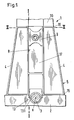
- Fig. 1 schematically shows in section a known construction of a crosshead large diesel engine 1 with base plate 2, stator 5 and cylinder section 10.
- the cylinder section 10 is used in a conventional manner for receiving cylinders, not shown.
- the stand 5, which is formed, for example, by welding together of steel sheets, has a bottom plate 15 and two outer walls 4 and forms together with the perpendicular perpendicular sliding surfaces 8 as shown in FIG two cross-section trapezoidal frame, which are interconnected by a common cover plate 16.
- the two opposite vertically extending sliding surfaces 8 are supported by a middle wall 17 which is arranged between the two trapezoidal frames.
- the stand 5 is arranged with the bottom plate 15 on the base plate 2, a Bearing saddle 13 with bearing shell 131 for supporting a crankshaft 3 includes.
- the crankshaft 3 with axis K is in a conventional manner with a crosshead 9 via an in Fig. 1 Not shown push rod 18 is connected.
- Fig. 2 shows a section according to Fig. 1 along the section line l - l by a preferred embodiment of an inventive cross-head large diesel engine 1, comprising the stator 5, which is arranged on the base plate 2 and the cylinder section 10, which is placed on the stator 5. Between the stator 5 and the cylinder section 10, a cover plate 16 and between the stator 10 and the base plate 2, a bottom plate 15 is arranged.
- the cylinder section 10 is suitable in a known manner for receiving one or more cylinders, not shown.
- the interior of the cylinder forms in a known manner together with a cylinder cover, not shown, and a piston, not shown, which is connected by a piston rod 19 with the crosshead 9 and arranged reciprocally in the cylinder, a combustion chamber of the crosshead large diesel engine 1.
- Der Stand 5 includes a support body 6, which is designed by transverse support walls 7 double-walled. The support walls 7 carry a Gleitf kaue 8 for guiding the crosshead 9, which is connected by means of a push rod 18 to the crankshaft 3 and the piston rod 19 with a piston, not shown, of the crosshead large diesel engine 1.
- the base plate 2 comprises for receiving and supporting the crankshaft 3, a bearing saddle 13 and a transverse support member 12 which is configured single-walled.
- Cylinder section 10, stator 5 and base plate 2 are interconnected by a tie rod 11 under bias.
- the tie rod 11 extends in the region of the upright 5 between the transverse support walls 7 within the double-walled support body 6 and is in the bearing saddle 13 of the base plate 2 in a region between the axis K of the crankshaft 3 and the stator 5, ie according to the representation above the axis K. the crankshaft 3, fixed in a threaded bore 14.
- the transverse support walls 7 of the support body 6 extend V-shaped in the direction of the cylinder section 10, that is, the mutual distance of the support walls 7 of a support body 6 increases increasingly toward the cylinder section 10.
- the normal forces, the crosshead 9 on the Gleitf kauen 8 transmits to the support walls 7 and thus to the support body 6, are known near the top dead center of the reciprocating motion of the piston largest. Due to the V-shaped configuration of the support body 6, this is relatively wide in the upper region of the upright 5, and can therefore absorb the normal forces of the crosshead 9 particularly well or dissipate them into the upright 5.
- the tie rod 11 extends with its longitudinal axis Z centrally between the transverse support walls 7 of the support body 6, wherein the single-walled support member 12 of the base plate 2, on which the support body 6 is supported in the base plate 2, aligned with the longitudinal axis Z des Tie rod 11 is arranged.
- the tie rod 11 is, in particular to avoid deformation of the bearing shells 131, fixed in a region between the axis K of the crankshaft 3 and the stator 5, as shown above the axis K of the crankshaft in the bearing saddle 13 in a threaded bore 14.
- the single-walled support member 12 is arranged in the base plate 2 in alignment with the longitudinal axis Z of the tie rod 11 and thus symmetrically with respect to the support walls 7 of the support body 6, results in a particularly high stability, without the base plate has a high rigidity.
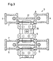
- Fig. 3 finally shows another cut according to Fig. 1 along the line II - II. Shown are each two in the stator 5 opposite support body 6, which are supported by the middle wall 17 between the sliding surfaces 8 against each other.
- the crosshead 9 is between two each opposite sliding surfaces 8 out of two adjacent support bodies 6.
- In each support body 6 extends between the support walls 7 exactly one tie rod eleventh
- the base plate of the cross-head large diesel engine according to the invention has a single-walled transversal support element, which can easily be welded against each other during assembly of the engine, so that the problems with the strength or the stability of the base plate, as they are known from the prior art Base plate with double-walled support elements result, can be avoided.
- the tie rods are preferably designed as short tie rods and fixed in an upper region of the saddle, that is, between the axis of the crankshaft and the bottom plate of the stator in a threaded bore. As a result, tension in the bearing saddle and deformations of the bearing shell are largely avoided by the fixed under considerable bias in the bearing saddle tie rods.
- the rigidity of the base plate of the inventive crosshead large diesel engine is optimized in particular by the short tie rods and the single-walled support elements. Since the tie rods must be anchored under considerable bias in the base plate, so far a combination of doppelwandigem support body in the stand with single-walled support element in the base plate was not considered, as both in the lower part of the stand and in the bottom plates, as well as in the area Storage saddle with unavoidable bending loads and resulting unacceptable mechanical stresses in the material calculated. By appropriate design of the stator and the base plate in the region of the tie rod both the previously feared problems could be avoided by bending loads, as well as expected in such a construction fretting. In particular, the bottom plate of the inventive large diesel engine has been significantly simplified structurally.
Landscapes
- Engineering & Computer Science (AREA)
- General Engineering & Computer Science (AREA)
- Mechanical Engineering (AREA)
- Chemical & Material Sciences (AREA)
- Combustion & Propulsion (AREA)
- Cylinder Crankcases Of Internal Combustion Engines (AREA)
- Shafts, Cranks, Connecting Bars, And Related Bearings (AREA)
Priority Applications (1)
| Application Number | Priority Date | Filing Date | Title |
|---|---|---|---|
| EP03405426A EP1382829B1 (de) | 2002-07-15 | 2003-06-16 | Kreuzkopf-Grossdieselmotor |
Applications Claiming Priority (3)
| Application Number | Priority Date | Filing Date | Title |
|---|---|---|---|
| EP02405607 | 2002-07-15 | ||
| EP02405607 | 2002-07-15 | ||
| EP03405426A EP1382829B1 (de) | 2002-07-15 | 2003-06-16 | Kreuzkopf-Grossdieselmotor |
Publications (2)
| Publication Number | Publication Date |
|---|---|
| EP1382829A1 EP1382829A1 (de) | 2004-01-21 |
| EP1382829B1 true EP1382829B1 (de) | 2008-10-29 |
Family
ID=31197997
Family Applications (1)
| Application Number | Title | Priority Date | Filing Date |
|---|---|---|---|
| EP03405426A Revoked EP1382829B1 (de) | 2002-07-15 | 2003-06-16 | Kreuzkopf-Grossdieselmotor |
Country Status (7)
| Country | Link |
|---|---|
| EP (1) | EP1382829B1 (ja) |
| JP (1) | JP4342224B2 (ja) |
| KR (1) | KR100992975B1 (ja) |
| CN (1) | CN100564830C (ja) |
| DE (1) | DE50310690D1 (ja) |
| DK (1) | DK1382829T3 (ja) |
| PL (1) | PL361265A1 (ja) |
Cited By (3)
| Publication number | Priority date | Publication date | Assignee | Title |
|---|---|---|---|---|
| EP2236802A1 (de) | 2009-03-20 | 2010-10-06 | Wärtsilä Schweiz AG | Kreuzkopf-Grossdieselmotor |
| EP2664819A1 (de) | 2012-05-16 | 2013-11-20 | Wärtsilä Schweiz AG | Kreuzkopf-Grossdieselmotor, sowie ein Ständer und ein Schwingungskompensator für einen Kreuzkopf-Grossdieselmotor |
| EP2664763A1 (de) | 2012-05-16 | 2013-11-20 | Wärtsilä Schweiz AG | Kreuzkopf-Grossdieselmotor, sowie ein Ständer und ein Schwingungskompensator für einen Kreuzkopf-Dieselmotor |
Families Citing this family (7)
| Publication number | Priority date | Publication date | Assignee | Title |
|---|---|---|---|---|
| EP1826387A2 (de) * | 2006-02-24 | 2007-08-29 | Wärtsilä Schweiz AG | Kreuzkopf-Grossdieselmotor |
| KR101419328B1 (ko) * | 2007-06-18 | 2014-07-14 | 베르트질레 슈바이츠 악티엔게젤샤프트 | 대형 크로스헤드 디젤 엔진 |
| EP2199583A2 (de) | 2008-12-18 | 2010-06-23 | Wärtsilä Schweiz AG | Kreuzkopf-Grossdieselmotor |
| KR20100127694A (ko) * | 2009-05-26 | 2010-12-06 | 베르트질레 슈바이츠 악티엔게젤샤프트 | 대형 크로스헤드 디젤 엔진 |
| JP5709621B2 (ja) * | 2011-04-07 | 2015-04-30 | 三菱重工業株式会社 | 架構 |
| JP6275611B2 (ja) * | 2014-09-26 | 2018-02-07 | 三菱重工業株式会社 | ガイド板、隔壁ユニット、架構及びクロスヘッド式内燃機関 |
| JP6675956B2 (ja) * | 2016-08-29 | 2020-04-08 | 三菱重工業株式会社 | 架構及びクロスヘッド式内燃機関 |
Family Cites Families (5)
| Publication number | Priority date | Publication date | Assignee | Title |
|---|---|---|---|---|
| NL20401C (ja) * | 1900-01-01 | |||
| US2045493A (en) * | 1932-12-14 | 1936-06-23 | Gen Electric | Welded frame for combustion engines |
| CH625603A5 (ja) * | 1977-10-27 | 1981-09-30 | Sulzer Ag | |
| DE3512347C1 (de) * | 1985-04-01 | 1986-10-30 | Gebrüder Sulzer AG, Winterthur | Ständer mit einer Abstützung der Kreuzkopfgleitbahnen |
| JPH11325389A (ja) * | 1998-05-13 | 1999-11-26 | Mitsubishi Heavy Ind Ltd | 架構の製造方法 |
-
2003
- 2003-06-16 EP EP03405426A patent/EP1382829B1/de not_active Revoked
- 2003-06-16 DK DK03405426T patent/DK1382829T3/da active
- 2003-06-16 DE DE50310690T patent/DE50310690D1/de not_active Expired - Fee Related
- 2003-06-19 KR KR1020030039915A patent/KR100992975B1/ko active IP Right Grant
- 2003-06-30 JP JP2003186037A patent/JP4342224B2/ja not_active Expired - Fee Related
- 2003-07-14 CN CNB031476031A patent/CN100564830C/zh not_active Expired - Fee Related
- 2003-07-14 PL PL03361265A patent/PL361265A1/xx unknown
Cited By (3)
| Publication number | Priority date | Publication date | Assignee | Title |
|---|---|---|---|---|
| EP2236802A1 (de) | 2009-03-20 | 2010-10-06 | Wärtsilä Schweiz AG | Kreuzkopf-Grossdieselmotor |
| EP2664819A1 (de) | 2012-05-16 | 2013-11-20 | Wärtsilä Schweiz AG | Kreuzkopf-Grossdieselmotor, sowie ein Ständer und ein Schwingungskompensator für einen Kreuzkopf-Grossdieselmotor |
| EP2664763A1 (de) | 2012-05-16 | 2013-11-20 | Wärtsilä Schweiz AG | Kreuzkopf-Grossdieselmotor, sowie ein Ständer und ein Schwingungskompensator für einen Kreuzkopf-Dieselmotor |
Also Published As
| Publication number | Publication date |
|---|---|
| JP2004044591A (ja) | 2004-02-12 |
| DE50310690D1 (de) | 2008-12-11 |
| KR100992975B1 (ko) | 2010-11-08 |
| KR20040007255A (ko) | 2004-01-24 |
| DK1382829T3 (da) | 2009-01-26 |
| CN100564830C (zh) | 2009-12-02 |
| JP4342224B2 (ja) | 2009-10-14 |
| CN1475662A (zh) | 2004-02-18 |
| PL361265A1 (en) | 2004-01-26 |
| EP1382829A1 (de) | 2004-01-21 |
Similar Documents
| Publication | Publication Date | Title |
|---|---|---|
| EP1826387A2 (de) | Kreuzkopf-Grossdieselmotor | |
| EP2236802A1 (de) | Kreuzkopf-Grossdieselmotor | |
| EP2199583A2 (de) | Kreuzkopf-Grossdieselmotor | |
| EP1382829B1 (de) | Kreuzkopf-Grossdieselmotor | |
| DE3512347C1 (de) | Ständer mit einer Abstützung der Kreuzkopfgleitbahnen | |
| DE2152462A1 (de) | Kolben fuer verbrennungskraftmaschinen | |
| DE3603352C2 (ja) | ||
| DE2124427C3 (de) | Anordnung einer Stoßstange an einem Kraftfahrzeug | |
| EP1440236A1 (de) | Hochdruckspeicher wie kraftstoffhochdruckspeicher | |
| EP2006523A1 (de) | Kreuzkopf-Grossdieselmotor | |
| DE2260142A1 (de) | Zylinder-kurbelgehaeuse | |
| DE19908670C2 (de) | Kolben für Brennkraftmaschinen | |
| DE2618241A1 (de) | Brennkraftmaschine | |
| DE102022122301A1 (de) | Mehrteiliges Maschinengestell für eine Schmiedemaschine | |
| DE4408101C2 (de) | Ein- oder Mehretagenpresse | |
| CH413508A (de) | Geteilter Pleuelstangenkopf | |
| DE3238489A1 (de) | Pleuelstange | |
| DE10018064A1 (de) | Pleuel | |
| DE102007008281A1 (de) | Hubkolbenbrennkraftmaschine | |
| DE3221860A1 (de) | Abstuetzeinrichtung an einem druckbehaelter, insbesondere einem reaktordruckbehaelter, gegen horizontalkraefte | |
| AT413299B (de) | Pleuelstange | |
| EP3354370B1 (de) | Oszillationssystem für eine stranggiesskokille, und verfahren zum erzeugen einer oszillationsbewegung einer stranggiesskokille | |
| DE102019120742B3 (de) | Kraftstoffverteiler | |
| CH712702A2 (de) | Hubkolbenbrennkraftmaschine, sowie Kurbelwelle für eine Hubkolbenbrennkraftmaschine. | |
| DE2708556C3 (de) | Hubkolben-Brennkraftmaschine als Schiffantrieb |
Legal Events
| Date | Code | Title | Description |
|---|---|---|---|
| PUAI | Public reference made under article 153(3) epc to a published international application that has entered the european phase |
Free format text: ORIGINAL CODE: 0009012 |
|
| AK | Designated contracting states |
Kind code of ref document: A1 Designated state(s): AT BE BG CH CY CZ DE DK EE ES FI FR GB GR HU IE IT LI LU MC NL PT RO SE SI SK TR |
|
| AX | Request for extension of the european patent |
Extension state: AL LT LV MK |
|
| 17P | Request for examination filed |
Effective date: 20040629 |
|
| AKX | Designation fees paid |
Designated state(s): DE DK FI IT |
|
| 17Q | First examination report despatched |
Effective date: 20070705 |
|
| GRAP | Despatch of communication of intention to grant a patent |
Free format text: ORIGINAL CODE: EPIDOSNIGR1 |
|
| GRAS | Grant fee paid |
Free format text: ORIGINAL CODE: EPIDOSNIGR3 |
|
| GRAA | (expected) grant |
Free format text: ORIGINAL CODE: 0009210 |
|
| AK | Designated contracting states |
Kind code of ref document: B1 Designated state(s): DE DK FI IT |
|
| REF | Corresponds to: |
Ref document number: 50310690 Country of ref document: DE Date of ref document: 20081211 Kind code of ref document: P |
|
| REG | Reference to a national code |
Ref country code: DK Ref legal event code: T3 |
|
| PLBI | Opposition filed |
Free format text: ORIGINAL CODE: 0009260 |
|
| PGFP | Annual fee paid to national office [announced via postgrant information from national office to epo] |
Ref country code: DK Payment date: 20090611 Year of fee payment: 7 |
|
| 26 | Opposition filed |
Opponent name: MAN DIESEL FILIAL AF MAN DIESEL SE, TYSKLAND Effective date: 20090710 |
|
| PLAX | Notice of opposition and request to file observation + time limit sent |
Free format text: ORIGINAL CODE: EPIDOSNOBS2 |
|
| PGFP | Annual fee paid to national office [announced via postgrant information from national office to epo] |
Ref country code: FI Payment date: 20090615 Year of fee payment: 7 Ref country code: IT Payment date: 20090620 Year of fee payment: 7 |
|
| PGFP | Annual fee paid to national office [announced via postgrant information from national office to epo] |
Ref country code: DE Payment date: 20090622 Year of fee payment: 7 |
|
| PLAF | Information modified related to communication of a notice of opposition and request to file observations + time limit |
Free format text: ORIGINAL CODE: EPIDOSCOBS2 |
|
| PLBB | Reply of patent proprietor to notice(s) of opposition received |
Free format text: ORIGINAL CODE: EPIDOSNOBS3 |
|
| RDAF | Communication despatched that patent is revoked |
Free format text: ORIGINAL CODE: EPIDOSNREV1 |
|
| PG25 | Lapsed in a contracting state [announced via postgrant information from national office to epo] |
Ref country code: FI Free format text: LAPSE BECAUSE OF NON-PAYMENT OF DUE FEES Effective date: 20100616 |
|
| REG | Reference to a national code |
Ref country code: DK Ref legal event code: EBP |
|
| RDAG | Patent revoked |
Free format text: ORIGINAL CODE: 0009271 |
|
| STAA | Information on the status of an ep patent application or granted ep patent |
Free format text: STATUS: PATENT REVOKED |
|
| PG25 | Lapsed in a contracting state [announced via postgrant information from national office to epo] |
Ref country code: IT Free format text: LAPSE BECAUSE OF NON-PAYMENT OF DUE FEES Effective date: 20100616 |
|
| 27W | Patent revoked |
Effective date: 20101220 |
|
| PG25 | Lapsed in a contracting state [announced via postgrant information from national office to epo] |
Ref country code: DK Free format text: LAPSE BECAUSE OF NON-PAYMENT OF DUE FEES Effective date: 20100630 |