EP1380400A1 - Spritzgiessdüse mit Nadelverschluss und seitlichen Austrittsöffnungen - Google Patents
Spritzgiessdüse mit Nadelverschluss und seitlichen Austrittsöffnungen Download PDFInfo
- Publication number
- EP1380400A1 EP1380400A1 EP03014792A EP03014792A EP1380400A1 EP 1380400 A1 EP1380400 A1 EP 1380400A1 EP 03014792 A EP03014792 A EP 03014792A EP 03014792 A EP03014792 A EP 03014792A EP 1380400 A1 EP1380400 A1 EP 1380400A1
- Authority
- EP
- European Patent Office
- Prior art keywords
- injection molding
- molding nozzle
- nozzle according
- needles
- closure
- Prior art date
- Legal status (The legal status is an assumption and is not a legal conclusion. Google has not performed a legal analysis and makes no representation as to the accuracy of the status listed.)
- Granted
Links
- 238000001746 injection moulding Methods 0.000 title claims abstract description 65
- 229920003023 plastic Polymers 0.000 claims abstract description 30
- 239000004033 plastic Substances 0.000 claims abstract description 30
- 230000006835 compression Effects 0.000 claims description 4
- 238000007906 compression Methods 0.000 claims description 4
- 230000037431 insertion Effects 0.000 claims 1
- 238000003780 insertion Methods 0.000 claims 1
- 230000015572 biosynthetic process Effects 0.000 abstract 2
- 238000002347 injection Methods 0.000 description 12
- 239000007924 injection Substances 0.000 description 12
- POIUWJQBRNEFGX-XAMSXPGMSA-N cathelicidin Chemical compound C([C@@H](C(=O)N[C@@H](CCCNC(N)=N)C(=O)N[C@@H](CCCCN)C(=O)N[C@@H](CO)C(=O)N[C@@H](CCCCN)C(=O)N[C@@H](CCC(O)=O)C(=O)N[C@@H](CCCCN)C(=O)N[C@@H]([C@@H](C)CC)C(=O)NCC(=O)N[C@@H](CCCCN)C(=O)N[C@@H](CCC(O)=O)C(=O)N[C@@H](CC=1C=CC=CC=1)C(=O)N[C@@H](CCCCN)C(=O)N[C@@H](CCCNC(N)=N)C(=O)N[C@@H]([C@@H](C)CC)C(=O)N[C@@H](C(C)C)C(=O)N[C@@H](CCC(N)=O)C(=O)N[C@@H](CCCNC(N)=N)C(=O)N[C@@H]([C@@H](C)CC)C(=O)N[C@@H](CCCCN)C(=O)N[C@@H](CC(O)=O)C(=O)N[C@@H](CC=1C=CC=CC=1)C(=O)N[C@@H](CC(C)C)C(=O)N[C@@H](CCCNC(N)=N)C(=O)N[C@@H](CC(N)=O)C(=O)N[C@@H](CC(C)C)C(=O)N[C@@H](C(C)C)C(=O)N1[C@@H](CCC1)C(=O)N[C@@H](CCCNC(N)=N)C(=O)N[C@@H]([C@@H](C)O)C(=O)N[C@@H](CCC(O)=O)C(=O)N[C@@H](CO)C(O)=O)NC(=O)[C@H](CC=1C=CC=CC=1)NC(=O)[C@H](CC(O)=O)NC(=O)CNC(=O)[C@H](CC(C)C)NC(=O)[C@@H](N)CC(C)C)C1=CC=CC=C1 POIUWJQBRNEFGX-XAMSXPGMSA-N 0.000 description 3
- 238000000034 method Methods 0.000 description 3
- 239000012778 molding material Substances 0.000 description 3
- 230000002349 favourable effect Effects 0.000 description 2
- 238000007789 sealing Methods 0.000 description 2
- 230000009286 beneficial effect Effects 0.000 description 1
- 230000007423 decrease Effects 0.000 description 1
- 230000009916 joint effect Effects 0.000 description 1
- 239000007788 liquid Substances 0.000 description 1
- 230000003716 rejuvenation Effects 0.000 description 1
- 230000001718 repressive effect Effects 0.000 description 1
- 238000000926 separation method Methods 0.000 description 1
- 239000007921 spray Substances 0.000 description 1
- 230000008646 thermal stress Effects 0.000 description 1
Images


Classifications
-
- B—PERFORMING OPERATIONS; TRANSPORTING
- B29—WORKING OF PLASTICS; WORKING OF SUBSTANCES IN A PLASTIC STATE IN GENERAL
- B29C—SHAPING OR JOINING OF PLASTICS; SHAPING OF MATERIAL IN A PLASTIC STATE, NOT OTHERWISE PROVIDED FOR; AFTER-TREATMENT OF THE SHAPED PRODUCTS, e.g. REPAIRING
- B29C45/00—Injection moulding, i.e. forcing the required volume of moulding material through a nozzle into a closed mould; Apparatus therefor
- B29C45/17—Component parts, details or accessories; Auxiliary operations
- B29C45/26—Moulds
- B29C45/27—Sprue channels ; Runner channels or runner nozzles
- B29C45/28—Closure devices therefor
- B29C45/2806—Closure devices therefor consisting of needle valve systems
-
- B—PERFORMING OPERATIONS; TRANSPORTING
- B29—WORKING OF PLASTICS; WORKING OF SUBSTANCES IN A PLASTIC STATE IN GENERAL
- B29C—SHAPING OR JOINING OF PLASTICS; SHAPING OF MATERIAL IN A PLASTIC STATE, NOT OTHERWISE PROVIDED FOR; AFTER-TREATMENT OF THE SHAPED PRODUCTS, e.g. REPAIRING
- B29C45/00—Injection moulding, i.e. forcing the required volume of moulding material through a nozzle into a closed mould; Apparatus therefor
- B29C45/17—Component parts, details or accessories; Auxiliary operations
- B29C45/26—Moulds
- B29C45/27—Sprue channels ; Runner channels or runner nozzles
- B29C45/2735—Sprue channels ; Runner channels or runner nozzles for non-coaxial gates, e.g. for edge gates
-
- B—PERFORMING OPERATIONS; TRANSPORTING
- B29—WORKING OF PLASTICS; WORKING OF SUBSTANCES IN A PLASTIC STATE IN GENERAL
- B29C—SHAPING OR JOINING OF PLASTICS; SHAPING OF MATERIAL IN A PLASTIC STATE, NOT OTHERWISE PROVIDED FOR; AFTER-TREATMENT OF THE SHAPED PRODUCTS, e.g. REPAIRING
- B29C45/00—Injection moulding, i.e. forcing the required volume of moulding material through a nozzle into a closed mould; Apparatus therefor
- B29C45/17—Component parts, details or accessories; Auxiliary operations
- B29C45/26—Moulds
- B29C45/27—Sprue channels ; Runner channels or runner nozzles
- B29C2045/2779—Nozzles with a plurality of outlets
-
- B—PERFORMING OPERATIONS; TRANSPORTING
- B29—WORKING OF PLASTICS; WORKING OF SUBSTANCES IN A PLASTIC STATE IN GENERAL
- B29C—SHAPING OR JOINING OF PLASTICS; SHAPING OF MATERIAL IN A PLASTIC STATE, NOT OTHERWISE PROVIDED FOR; AFTER-TREATMENT OF THE SHAPED PRODUCTS, e.g. REPAIRING
- B29C45/00—Injection moulding, i.e. forcing the required volume of moulding material through a nozzle into a closed mould; Apparatus therefor
- B29C45/17—Component parts, details or accessories; Auxiliary operations
- B29C45/26—Moulds
- B29C45/27—Sprue channels ; Runner channels or runner nozzles
- B29C45/28—Closure devices therefor
- B29C45/2806—Closure devices therefor consisting of needle valve systems
- B29C45/281—Drive means therefor
- B29C2045/2813—Common drive means for several needle valves
-
- B—PERFORMING OPERATIONS; TRANSPORTING
- B29—WORKING OF PLASTICS; WORKING OF SUBSTANCES IN A PLASTIC STATE IN GENERAL
- B29C—SHAPING OR JOINING OF PLASTICS; SHAPING OF MATERIAL IN A PLASTIC STATE, NOT OTHERWISE PROVIDED FOR; AFTER-TREATMENT OF THE SHAPED PRODUCTS, e.g. REPAIRING
- B29C45/00—Injection moulding, i.e. forcing the required volume of moulding material through a nozzle into a closed mould; Apparatus therefor
- B29C45/17—Component parts, details or accessories; Auxiliary operations
- B29C45/26—Moulds
- B29C45/27—Sprue channels ; Runner channels or runner nozzles
- B29C45/28—Closure devices therefor
- B29C45/2806—Closure devices therefor consisting of needle valve systems
- B29C45/281—Drive means therefor
- B29C2045/2831—Needle valves driven by a cam
-
- B—PERFORMING OPERATIONS; TRANSPORTING
- B29—WORKING OF PLASTICS; WORKING OF SUBSTANCES IN A PLASTIC STATE IN GENERAL
- B29C—SHAPING OR JOINING OF PLASTICS; SHAPING OF MATERIAL IN A PLASTIC STATE, NOT OTHERWISE PROVIDED FOR; AFTER-TREATMENT OF THE SHAPED PRODUCTS, e.g. REPAIRING
- B29C45/00—Injection moulding, i.e. forcing the required volume of moulding material through a nozzle into a closed mould; Apparatus therefor
- B29C45/17—Component parts, details or accessories; Auxiliary operations
- B29C45/26—Moulds
- B29C45/27—Sprue channels ; Runner channels or runner nozzles
- B29C45/28—Closure devices therefor
- B29C45/2806—Closure devices therefor consisting of needle valve systems
- B29C45/281—Drive means therefor
Definitions
- the invention relates to an injection molding of plastic at least two in their end to different sides directed outlet openings for applying different Gate openings and with a supply channel for the plastic too the outlet openings.
- Such injection molding nozzles are known and have in practice usually at least two or four radially to the side Outlet openings, for example, several cylindrical To be able to simultaneously spray plastic parts on the side.
- the one located in the outlet opening Plastic cool and thus forms a cold plug.
- this cold graft must be conveyed by the injection pressure in the form, which is due to the Outlets of the outlet openings at different times take place and can lead to different fillings.
- the sprayed parts first with the sprue and the connected in the nozzle plastic and must be Remove it from being demolished, resulting in an unsightly sprue or even damage the sprayed parts can.
- the initially defined injection molding characterized in that the according to various Side-facing outlet openings each have a needle closure with an adjustable in the direction of the outlet opening Valve needle and a drive for adjusting the valve pins has in its closed position.
- substantially open injection molding with several outlet openings these outlet openings So provided with needle closures, so that after the injection molding the outlet openings for the Plastic can be closed, so no connection more about the sprayed part. Also a cold stopper in the mouth region of the outlet openings is avoided so that a next injection molding facilitates accordingly is.
- the sprayed part of the outlet opening with the help of Locking pins a very accurate, hardly or not recognizable Sprue on the sprayed part.
- the injection molding nozzle can be equipped with a valve pin for each lateral outlet opening a separate feed channel for have the plastic and these feed channels can be outside be arranged the means of the injection molding.
- a valve pin for each lateral outlet opening a separate feed channel for have the plastic and these feed channels can be outside be arranged the means of the injection molding.
- a particularly advantageous embodiment of the invention can consist in that the closure needles of the outlet openings a common drive at least to move into their Have closed position. Because these valve pins are arranged radially are, their are the mouth of the outlet opposite ends relatively close together, so that the Using a common drive with a corresponding Simplification of the entire mechanism is well possible. Important is mainly the drive for moving in the closed position, while for the opposite adjustment movement of the closure needles in a conventional manner, the injection molding can be exploited.
- closure needles can be seen in the closing direction before the Mouth of the feed channel for the plastic a cross-sectional enlargement or a collar or the like as the effective area for the injection molding pressure to open the valve pin have and the drive acting in the closing direction can during the Opening the respective valve pin off and / or be overcome.
- a cross-sectional enlargement can have a correspondingly large force to open each one Shutter pin be generated during a new injection cycle.
- Mechanical adjustment have the advantage over compression springs that they be brought into position during opening of the needle can, which generates no back pressure such as a compression spring.
- a common drive element for adjusting several or all valve pins in Closing direction is provided and if this drive element a movable between the ends of a plurality of valve pins, different cross sections having adjusting body, for example a cone, cone or the like rejuvenates Element or a cam or eccentric or the like is. So it can either be a cone or cone between the Ends of the valve pins are pushed deeper, thereby these ends apart and thus the shutter needles in Closed position to be moved.
- Push and pull rod or for turning a cam or eccentric disc can be a central in the injection molding nozzle arranged rotating rod may be provided. So one is enough single rod to mechanically lock the multiple valve pins to force them to move to the closed position, this rod is perpendicular to the movement of the closure needles and also at right angles to its longitudinal extent can be arranged, so in turn at their end well with a corresponding rotary or axial drive, in particular a Piston, a spindle drive can be provided or coupled.
- a further embodiment of the invention and in particular the Actuation of the closure needles may consist in that the on the closure needles attacking drive element so with This coupled and connected, that is a movement for Closing and the opposite movement to pull back the shutter needles in their open position is used.
- the on the closure needles attacking drive element so with This coupled and connected, that is a movement for Closing and the opposite movement to pull back the shutter needles in their open position is used.
- the on the closure needles attacking drive element so with This coupled and connected, that is a movement for Closing and the opposite movement to pull back the shutter needles in their open position is used.
- the on the closure needles attacking drive element so with This coupled and connected, that is a movement for Closing and the opposite movement to pull back the shutter needles in their open position is used.
- a conical repressive body between the needle ends with corresponding mutual entanglements and Guides on the needle ends attack so that even when retracting this cone body due to the positive connection with the needle end this then retracted back
- An embodiment of the invention of considerably more advantageous Meaning can be that the housing of the Injection nozzle divided transversely to the feed channels for the plastic is and in the area of the subdivision a heat balance gap Has. This can be achieved by virtue of of the hot injection molding material occurring thermal movements of stay away from the valve pins and their bearings, So the mouths of the outlet openings and the closure needles despite the thermal movements their position exactly maintained. Nevertheless, the nozzle housing can occur Perform thermal expansion and thermal movements.
- the heat balance gap on the Housing of the injection nozzle at least in the region of the feed channels for the plastic by an overlap or the like is sealed. This will ensure that in the area of the heat balance gap no injection molding material emerge and block later heat movements.
- a structurally favorable arrangement results when the outlet openings and the lock pins movable therein inserted into the housing of the injection molding and optionally exchangeable sleeves are arranged. This facilitates the assembly and the possible replacement of the valve pins.
- the closure needles each from the outside in their storage axially insertable and by means of a on the outside screw the housing, the mouth of the outlet opening having retaining cap be defined.
- this retaining cap unscrewed again be able to pull out the valve pin.
- These caps themselves, which are the mouth of the outlet can be easily replaced accordingly.
- closure needles in the female sleeve before they are inserted into the Düsenharm from the later inside of insertable and by means of a collar, a cross-sectional enlargement or the like be fixed in the axial direction such that the Adjusting movement in the closing direction limited and the valve pin is fixed in the radial direction.
- This can the mentioned diameter increase, which also the injection molding pressure convert into an opening movement of the valve pin can, get a double function.
- adjustable closure needles on the same nozzle housing in particular arranged in the same plane and with the same drive element be movable in the closed position.
- a generally designated 1 injection molding for plastic has at least two in its end to different Side directed outlet openings 2 for applying different Gullies on different forms 3 on, from which in each case only one is shown in Fig. 1 to 11. you but recognizes in all these figures next to the outlet 2, which leads to the illustrated form 3 and is directed, the oppositely directed further outlet opening 2, with the another form can and should be applied.
- this injection molding nozzle 1 a feed channel 4 for the plastic to the outlet openings Second
- the outlet openings 5 can also as Channels are considered, in which the shut-off needles 5 hin- and are movable and in front of the mouths 6 of these channels or Outlet openings 2, the feed channels 4 from the side Come in, being in their end just before the entrance still a change in direction towards the mouth 6 back can have.
- the outlet openings 2 and the sliding in them lock pins 5 are as shown in Figures 1, 6, 8, 9 and 11 about radially and in particular in the same transversely to the longitudinal central axis arranged the injection molding nozzle 1 extending plane, so they can also be operated together.
- the closure needles 5 have one thing to describe, different executable drive for moving at least in its closed position.
- a cross-sectional enlargement 8 in the form of a paragraph or possibly a covenant or the like have as active surface for the injection molding to open the valve needle 5 and acting in the closing direction drive during the opening of the respective valve needle 5 is turned off or surmounted.
- the sealing needles 5 can be displaced backwards by the liquid plastic and its pressure from its closed position, so that the injection pressure acts on the cross-sectional enlargement 8 and the corresponding closure needle 5 moves back like a piston so that the mouth 6 of the outlet opening 2 of FIG the needle 5 and its closure end is released.
- adjusting means are provided, which are Borver Victoria for this process of moving the shutter needle 5 in the open position in a corresponding position.
- each is a common Drive element for adjusting several or all Locking pins 5 provided in the closing direction and this drive element is one between the facing each other Ends of several shutter needles 5 movable, different Cross sections having adjusting body.
- this adjusting body is a cone 9 or cone or the like rejuvenating Element that with its initially smaller cross-section between the ends of the closure needles 5 engages and by its own axial adjustment these ends of the closure needles and thus the needles 5 themselves in the radial direction move apart so they can be in theirs at the same time Get closed positions.
- the drawings show each case this closed position.
- the adjusting body but also be a cam or eccentric disc 10 whose circumference varies from a smaller to a larger size and vice versa.
- this disk is rotated from the position shown in Fig. 6, for example, in the clockwise direction to reach the closed position shown in FIGS. 8 and 11.
- FIGS. 9 and 10 show such a closed position of the shutter needles 5.
- a piston 12 engages in a not shown Cylinder by a pressure medium acted upon and is adjustable to move the rod 11 and the cone 9 located thereon accordingly.
- the cam or eccentric 10 For rotating the cam or eccentric 10 is a centrally arranged in the injection molding nozzle 1 rotary rod 13 at which a corresponding rotary drive of any design can attack.
- the housing 14 of the injection nozzle is divided transversely to the feed channels 4 is and in the area of the subdivision a heat balance gap 15 has. This can be achieved that thermal movements be absorbed by this heat compensation gap 15, So the needles 5 their precise position despite keep such heat movements and not by thermal stresses be charged.
- the heat compensation gap 15 is at least in the housing 14 sealed in the region of the feed channels 4, by that in the region of the feed channels 4 sliding sleeves 16 at the outside or according to the embodiments inside of the respective feed channel 4 are arranged. This will ensure that despite this heat balance gap 15 of the Injection molding do not escape from the feed channels 4 can.
- the outlet openings 2 and the therein displaceable closure needles 5 are interchangeable in all embodiments
- Sleeves 17 arranged in the housing 14 of the Injection molding 1 - preferably interchangeable - are used. This facilitates the assembly especially of the closure needles 5 and their replacement in case of wear.
- closure needles 5 can also be from the outside in their located in these sleeves 17 bearing axially inserted and by means of a screwed on the outside, the Mouth 6 of the outlet opening 2 having retaining cap 18th be determinable.
- This arrangement can be seen in Figures 2 to 3 and in Figures 6 to 8.
- such a retaining cap 18 is not provided and the mouth 6 corresponding opening in the form of the third misplaced, in which the corresponding closure end of the valve pin 5 is displaceable.
- the retaining cap 18 has yet another function by Namely, the shutter needle 5 at the cross-sectional enlargement 8 against accidental leakage from storage could hinder while in the embodiments without a such retaining cap 18 is a corresponding counter-stop 19 for the cross-sectional enlargement 8 could be provided. In both Cases is therefore the shutter needle 5 in its axial Direction determined such that the adjustment movement in Closing direction limited and the shutter needle 5 in the radial Direction is set.
- each oriented locking pins 5 are provided, but could be in the same nozzle housing 14 even in the same plane even more
- the injection molding nozzle 1 for plastic with at least 2 after different Sides and oppositely directed outlets 2 is not designed as an open injection nozzle, but has in the outlet openings 2 each have a closure needle 5, for which valve needles 5 and a drive for Adjustment is provided at least in the closed position. Consequently For example, a cold plug can be applied to the mold 3 Regardless of the end of the outlet openings 2 whether the shutter needles these outlet openings 2 at their Completely close mouth 6 or even a minimal one Release gap.
Abstract
Description
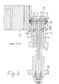
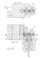
- Fig. 1
- eine Ansicht einer erfindungsgemäßen Spritzgießdüse in Verbindung mit einer der von ihr zu beaufschlagenden Formen,
- Fig. 2
- einen Längsschnitt eines Ausführungsbeispiels der erfindungsgemäßen Spritzgießdüse gemäß der Schnittlinie A-A in Fig. 1, wobei in den voneinander weggerichteten Austrittsöffnungen jeweils eine Verschlussnadel angeordnet ist und diese Verschlussnadeln durch einen an ihren einander zugewandten Enden gleichzeitig angreifenden Konuskörper aus einer Offenstellung in die dargestellte Schließposition verschoben sind,
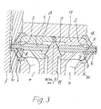
- Fig. 3
- in vergrößertem Maßstab die Verschlussnadeln und den sie gemeinsam beaufschlagenden Konuskörper in Schließstellung, wobei die Mündungen der Austrittsöffnungen durch separate, am Düsengehäuse befestigte Kappen gebildet sind,
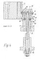
- Fig. 4
- einen Längsschnitt gemäß der Linie A-A in Fig. 1 eines abgewandelten Ausführungsbeispiels, bei welchem die durch die Verschlussnadeln ganz oder teilweise verschließbaren Mündungen in die jeweilige Form eingearbeitet sind,
- Fig. 5
- eine vergrößerte Darstellung der Verschlussnadeln gemäß Fig. 4,
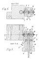
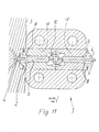
- Fig. 6
- einen Querschnitt gemäß der Linie B-B in Fig. 7 und
- Fig. 7
- einen Längsschnitt gemäß der Schnittlinie A-A in Fig. 1 betreffend ein Ausführungsbeispiel, bei welchem zwischen den Enden der Verschlussnadeln eine durch eine Drehstange beaufschlagte Nockenscheibe angeordnet ist, wobei die Verschlussnadeln sich in Offenstellung befinden und die Mündung der Austrittsöffnung in einer separaten Kappe angeordnet sind,
- Fig. 8
- eine vergrößerte Darstellung der Verschlussnadeln gemäß Fig. 6 und 7 in Schließstellung,
- Fig. 9
- eine der Fig. 6 entsprechende Darstellung eines Ausführungsbeispiels mit einer Nockenscheibe zwischen den Enden der Verschlussnadeln, wobei die durch die Nadel zu verschließende oder teilweise zu verschließende Mündung in die Form eingearbeitet ist,
- Fig. 10
- einen Schnitt gemäß der Linie A-A in Fig. 1 bei einer Ausführungsform gemäß Fig. 9 sowie
- Fig. 11
- in vergrößerter Darstellung die Verschlussnadeln mit der zwischen ihren Enden angeordneten Exzenterscheibe gemäß Fig. 9 und 10 in Schließposition.
Dient als Antrieb zum Verschließen der Verschlussnadeln 5 eine oder mehrere Druckfedern, wird deren Kraft durch den Spritzgießdruck einfach überwunden. In den Ausführungsbeispielen sind jedoch noch zu beschreibende Verstellmittel vorgesehen, die für diesen Vorgang des Verschiebens der Verschlussnadel 5 in Offenstellung in eine entsprechende Position zurückverstellt werden.
Zum Verstellen des kegelförmigen oder Konuskörpers 9 dient gemäß Fig. 2 bis 5 eine in axialer Richtung zentral innerhalb der Spritzgießdüse 1 verstellbare Schub- und Zugstange 11, an deren Ende gemäß Fig. 2 und 4 ein Kolben 12 angreift, der in einem nicht näher dargestellten Zylinder durch ein Druckmedium beaufschlagbar hin- und herverstellbar ist, um die Stange 11 und den daran befindlichen Konus 9 entsprechend zu verschieben. Es könnte aber auch jedes beliebige andere geeignete Antriebselement an dieser Stange 11 angreifen.
Claims (18)
- Spritzgießdüse (1) für Kunststoff mit wenigstens zwei in ihrem Endbereich nach verschiedenen Seiten gerichteten Austrittsöffnungen (2) zum Beaufschlagen verschiedener Angussöffnungen und mit einem Zuführkanal (4) für den Kunststoff zu den Austrittsöffnungen (2), dadurch gekennzeichnet, dass die nach verschiedenen Seiten gerichteten Austrittsöffnungen (2) jeweils einen Nadelverschluss mit einer in Richtung der Austrittsöffnung (2) verstellbaren Verschlussnadel (5) sowie einen Antrieb zum Verstellen der Verschlussnadeln (5) in deren Schließposition aufweisen.
- Spritzgießdüse nach Anspruch 1, dadurch gekennzeichnet, dass sie für jede mit einer Verschlussnadel (5) versehene seitliche Austrittsöffnung (2) einen eigenen Zuführkanal (4) für den Kunststoff aufweist und die Zuführkanäle (4) außerhalb der Mitte der Spritzgießdüse (1) angeordnet sind.
- Nadelverschlussdüse nach Anspruch 1 oder 2, dadurch gekennzeichnet, dass die Zuführkanäle (4) für den Kunststoff nahe den Enden der einzelnen Verschlussnadel (5) vor den Mündungen (6) der Austrittsöffnungen (2) in diese eintreten.
- Spritzgießdüse nach einem der Ansprüche 1 bis 3, dadurch gekennzeichnet, dass die Austrittsöffnungen (2) und die in ihnen verschiebbaren Verschlussnadeln (5) etwa radial und insbesondere in der selben quer zur Längsmittelachse der Spritzgießdüse (1) verlaufenden Ebene angeordnet sind.
- Spritzgießdüse nach einem der Ansprüche 1 bis 4, dadurch gekennzeichnet, dass die Verschlussnadeln (5) der Austrittsöffnungen (2) einen gemeinsamen Antrieb zumindest zum Verschieben in ihre Schließposition haben.
- Spritzgießdüse nach einem der Ansprüche 1 bis 5, dadurch gekennzeichnet, dass die Verschlussnadeln (5) in Schließrichtung gesehen vor dem Eintritt des Zuführkanals (4) für den Kunststoff eine Querschnittsvergrößerung (8) oder einen Bund oder dergleichen als Wirkfläche für den Spritzgießdruck zum Öffnen der Verschlussnadel (5) haben und der in Schließrichtung wirkende Antrieb während des Öffnens der jeweiligen Verschlussnadel (5) ausschaltbar und/oder überwindbar ist.
- Spritzgießdüse nach einem der Ansprüche 1 bis 6, dadurch gekennzeichnet, dass zum Verschieben der,Verschlussnadeln (5) in Schließstellung Druckfedern und/oder mechanisch an den Verschlussnadeln (5), insbesondere an ihrem der Austrittsöffnung abgewandten Ende angreifende Verstellmittel vorgesehen sind.
- Spritzgießdüse nach einem der Ansprüche 1 bis 7, dadurch gekennzeichnet, dass ein gemeinsames Antriebselement zum Verstellen mehrerer oder aller Verschlussnadeln (5) in Schließrichtung vorgesehen ist und dass dieses Antriebselement ein zwischen den Enden mehrerer Verschlussnadeln (5) bewegbarer, unterschiedliche Querschnitte aufweisender Verstellkörper, beispielsweise ein Konus (9), Kegel oder dergleichen sich verjüngendes Element oder eine Nocken- oder Exzenterscheibe (10) oder dergleichen ist.
- Spritzgießdüse nach einem der Ansprüche 1 bis 8, dadurch gekennzeichnet, dass zum Verstellen eines kegelförmigen oder Konuskörpers (9) eine in axialer Richtung zentral innerhalb der Spritzgießdüse (1) verstellbare Schub- und Zugstange (11) oder zum Verdrehen einer Nocken- oder Exzenterscheibe (10) eine zentral in der Spritzgießdüse (1) angeordnete Drehstange (13) vorgesehen ist.
- Spritzgießdüse nach einem der Ansprüche 1 bis 9, dadurch gekennzeichnet, dass das an den Verschlussnadeln (5) angreifende Antriebselement derart mit diesen gekuppelt und verbunden ist, dass die eine Bewegung zum Verschließen und die entgegengesetzte Bewegung zum Zurückziehen der Verschlussnadeln (5) in ihre Öffnungsposition dient.
- Spritzgießdüse nach einem der vorstehenden Ansprüche, dadurch gekennzeichnet, dass ihr Gehäuse (14) quer zu den Zuführkanälen (4) für den Kunststoff unterteilt ist und im Bereich der Unterteilung einen Wärmeausgleichsspalt (15) hat.
- Spritzgießdüse nach einem der Ansprüche 1 bis 11, dadurch gekennzeichnet, dass der Wärmeausgleichsspalt (15) an dem Gehäuse (14) der Spritzgießdüse zumindest im Bereich der Zuführkanäle (4) für den Kunststoff durch einen Überlappung oder dergleichen abgedichtet ist.
- Spritzgießdüse nach einem der Ansprüche 1 bis 12, dadurch gekennzeichnet, dass die zur Abdichtung des Wärmeausgleichsspalts (15) im Bereich der Zuführkanäle (4) dienende Überlappung durch Schiebehülsen (16), insbesondere durch jeweils eine an der Innenseite oder Außenseite des Zuführkanals (4) angeordnete Schiebehülse (16) gebildet ist.
- Spritzgießdüse nach einem der Ansprüche 1 bis 13, dadurch gekennzeichnet, dass die im Zentrum des Düsengehäuses (14) angeordnete Stange (11;13) für den gemeinsamen Antrieb der Verschlussnadeln (5) mit einem Dreh- oder Axialantrieb, insbesondere einem Kolben (12), einem Spindelantrieb oder dergleichen versehen oder gekuppelt ist.
- Spritzgießdüse nach einem der Ansprüche 1 bis 14, dadurch gekennzeichnet, dass die Austrittsöffnungen (2) und die darin verschiebbaren Verschlussnadeln (5) in in das Gehäuse (14) der Spritzgießdüse (1) eingesetzten und gegebenenfalls austauschbaren Hülsen angeordnet sind.
- Spritzgießdüse nach einem der Ansprüche 1 bis 15, dadurch gekennzeichnet, dass die Verschlussnadeln (5) jeweils von außen in ihre Lagerstelle axial einfuhrbar und mittels einer an der Außenseite anschraubbaren, die Mündung (6) der Austrittsöffnung (2) aufweisenden Haltekappe (18) festlegbar sind.
- Spritzgießdüse nach einem der Ansprüche 1 bis 16, dadurch gekennzeichnet, dass die Verschlussnadeln (5) in die sie aufnehmende Hülse (17) vor deren Einsetzen in den Düsenkörper von der späteren Innenseite aus einschiebbar und mittels eines Bundes, einer Querschnittsvergrößerung oder dergleichen in axialer Richtung derart festlegbar sind, dass die Verstellbewegung in Schließrichtung begrenzt und die Verschlussnadel (5) in radialer Richtung festgelegt ist.
- Spritzgießdüse nach einem der Ansprüche 1 bis 17, dadurch gekennzeichnet, dass mehr als zwei Austrittsöffnungen mit darin verstellbaren Verschlussnadeln (5) an dem selben Düsengehäuse (14) insbesondere in der selben Ebene angeordnet und mit dem selben Antriebselement in Schließstellung bewegbar sind.
Applications Claiming Priority (2)
| Application Number | Priority Date | Filing Date | Title |
|---|---|---|---|
| DE10231093A DE10231093C1 (de) | 2002-07-10 | 2002-07-10 | Spritzgießdüse für Kunststoff mit wenigstens zwei Austrittsöffnungen |
| DE10231093 | 2002-07-10 |
Publications (2)
| Publication Number | Publication Date |
|---|---|
| EP1380400A1 true EP1380400A1 (de) | 2004-01-14 |
| EP1380400B1 EP1380400B1 (de) | 2009-02-18 |
Family
ID=28685367
Family Applications (1)
| Application Number | Title | Priority Date | Filing Date |
|---|---|---|---|
| EP03014792A Expired - Lifetime EP1380400B1 (de) | 2002-07-10 | 2003-06-28 | Spritzgiessdüse mit Nadelverschluss und seitlichen Austrittsöffnungen |
Country Status (9)
| Country | Link |
|---|---|
| US (1) | US7322817B2 (de) |
| EP (1) | EP1380400B1 (de) |
| JP (1) | JP4382404B2 (de) |
| AT (1) | ATE422995T1 (de) |
| CA (1) | CA2434420C (de) |
| DE (2) | DE10231093C1 (de) |
| DK (1) | DK1380400T3 (de) |
| ES (1) | ES2319628T3 (de) |
| PT (1) | PT1380400E (de) |
Cited By (1)
| Publication number | Priority date | Publication date | Assignee | Title |
|---|---|---|---|---|
| DE202009004786U1 (de) | 2009-05-06 | 2010-09-23 | EWIKON Heißkanalsysteme GmbH & Co. KG | Heißkanaldüse zur Seitenanspritzung |
Families Citing this family (17)
| Publication number | Priority date | Publication date | Assignee | Title |
|---|---|---|---|---|
| US7410353B2 (en) * | 2004-10-20 | 2008-08-12 | Mold-Masters (2007) Limited | Edge gated injection molding apparatus |
| DE102005017413B4 (de) * | 2005-04-15 | 2008-06-26 | Otto Männer Innovation GmbH | Spritzgießdüse mit zwei Austrittsöffnungen |
| US7547208B2 (en) * | 2006-06-16 | 2009-06-16 | Mold-Masters (2007) Limited | Individual cavity shut-off valve for an injection molding apparatus |
| US7803306B2 (en) * | 2006-06-16 | 2010-09-28 | Mold-Masters (2007) Limited | Individual cavity shut-off valve for an injection molding apparatus |
| DE602007004819D1 (de) * | 2006-12-22 | 2010-04-01 | Mold Masters 2007 Ltd | Spritzgießvorrichtung mit seitlichen Angussöffnungen |
| US7658606B2 (en) * | 2006-12-22 | 2010-02-09 | Mold-Masters (2007) Limited | Edge gated injection molding apparatus |
| ATE544573T1 (de) * | 2006-12-29 | 2012-02-15 | Mold Masters 2007 Ltd | SPRITZGIEßVORRICHTUNG MIT SEITLICHER ANGUSSÖFFNUNG |
| DE102008028577B4 (de) * | 2007-06-20 | 2016-11-10 | Mold-Masters (2007) Limited | Eckenangussspritzgießvorrichtung |
| EP2390075A1 (de) * | 2010-05-31 | 2011-11-30 | Electrolux Home Products Corporation N.V. | Verfahren und Formausrüstung zur Herstellung eines Kuststoffrads und dadurch erhaltenes Rad |
| EP2397301B1 (de) * | 2010-06-16 | 2014-10-01 | Mold-Masters (2007) Limited | Düse mit Seitenanschnitt |
| KR101283666B1 (ko) * | 2011-03-04 | 2013-07-08 | 주식회사 유도 | 수평형 밸브 시스템이 구비된 핫런너 시스템 |
| EP3172024B1 (de) | 2014-04-01 | 2019-02-06 | Otto Männer Innovation GmbH | Seitliche angussdüse für spritzgiessvorrichtung |
| WO2016081334A1 (en) | 2014-11-17 | 2016-05-26 | Husky Injection Modling Systems Ltd. | Hot runner nozzle with a gate pressure equalizer |
| DE102015208145A1 (de) | 2015-04-30 | 2016-11-03 | Otto Männer Innovation GmbH | Düse für eine Spritzgießvorrichtung |
| US10800082B2 (en) * | 2018-08-14 | 2020-10-13 | Otto Männer GmbH | Hot runner injection nozzle and drive train |
| DE102020115942A1 (de) | 2020-06-17 | 2021-12-23 | EWIKON Heißkanalsysteme GmbH | Heißkanaldüse zur Seitenanspritzung |
| CN111844603B (zh) * | 2020-07-17 | 2022-01-14 | 平湖市中美包装科技有限公司 | 一种工业生产用注塑机 |
Citations (4)
| Publication number | Priority date | Publication date | Assignee | Title |
|---|---|---|---|---|
| EP0186413A2 (de) * | 1984-12-21 | 1986-07-02 | Tanner AG | Einrichtung zum Spritzgiessen von Kunststoffen |
| EP0407971A2 (de) * | 1989-07-13 | 1991-01-16 | Mold-Masters Limited | Spritzgiesssystem mit geflanschter isolierter Angussdichtung |
| EP0447573A1 (de) * | 1990-03-17 | 1991-09-25 | Dipl.-Ing. Herbert Günther Gesellschaft mbH | Heisskanaldüse |
| JPH11277573A (ja) * | 1998-03-27 | 1999-10-12 | Toyoda Gosei Co Ltd | 多段取りサンドイッチ成形装置 |
Family Cites Families (7)
| Publication number | Priority date | Publication date | Assignee | Title |
|---|---|---|---|---|
| US2471683A (en) * | 1945-09-06 | 1949-05-31 | Bolta Company | Multiple nozzle mechanism for injection molding machines |
| US4304544A (en) * | 1974-10-21 | 1981-12-08 | Fast Heat Element Mfg. Co., Inc. | Electrically heated nozzles and nozzle systems |
| US4662837A (en) * | 1985-03-18 | 1987-05-05 | Husky Injection Molding Systems, Ltd. | Apparatus for injection molding |
| DE4206318C2 (de) * | 1992-02-29 | 1994-06-16 | Otto Maenner | Mehrfach-Nadelverschluß-Düse für Spritzgießformen |
| CA2264224A1 (en) * | 1999-02-26 | 2000-08-26 | Denis Babin | Multi-cavity injection molding apparatus splitting melt near nozzle front |
| DE10008471B4 (de) * | 2000-02-24 | 2009-10-29 | EWIKON Heißkanalsysteme GmbH & Co. KG | Elektrisch beheizbares Heißkanalendstück |
| US6755641B1 (en) * | 2000-09-01 | 2004-06-29 | Mold-Masters Limited | Stack injection molding apparatus with separately actuated arrays of valve gates |
-
2002
- 2002-07-10 DE DE10231093A patent/DE10231093C1/de not_active Expired - Fee Related
-
2003
- 2003-06-28 DK DK03014792T patent/DK1380400T3/da active
- 2003-06-28 ES ES03014792T patent/ES2319628T3/es not_active Expired - Lifetime
- 2003-06-28 EP EP03014792A patent/EP1380400B1/de not_active Expired - Lifetime
- 2003-06-28 DE DE50311182T patent/DE50311182D1/de not_active Expired - Lifetime
- 2003-06-28 AT AT03014792T patent/ATE422995T1/de active
- 2003-06-28 PT PT03014792T patent/PT1380400E/pt unknown
- 2003-07-09 CA CA2434420A patent/CA2434420C/en not_active Expired - Lifetime
- 2003-07-09 JP JP2003194249A patent/JP4382404B2/ja not_active Expired - Fee Related
- 2003-07-10 US US10/616,824 patent/US7322817B2/en not_active Expired - Lifetime
Patent Citations (4)
| Publication number | Priority date | Publication date | Assignee | Title |
|---|---|---|---|---|
| EP0186413A2 (de) * | 1984-12-21 | 1986-07-02 | Tanner AG | Einrichtung zum Spritzgiessen von Kunststoffen |
| EP0407971A2 (de) * | 1989-07-13 | 1991-01-16 | Mold-Masters Limited | Spritzgiesssystem mit geflanschter isolierter Angussdichtung |
| EP0447573A1 (de) * | 1990-03-17 | 1991-09-25 | Dipl.-Ing. Herbert Günther Gesellschaft mbH | Heisskanaldüse |
| JPH11277573A (ja) * | 1998-03-27 | 1999-10-12 | Toyoda Gosei Co Ltd | 多段取りサンドイッチ成形装置 |
Non-Patent Citations (1)
| Title |
|---|
| PATENT ABSTRACTS OF JAPAN vol. 2000, no. 01 31 January 2000 (2000-01-31) * |
Cited By (2)
| Publication number | Priority date | Publication date | Assignee | Title |
|---|---|---|---|---|
| DE202009004786U1 (de) | 2009-05-06 | 2010-09-23 | EWIKON Heißkanalsysteme GmbH & Co. KG | Heißkanaldüse zur Seitenanspritzung |
| US8899963B2 (en) | 2009-05-06 | 2014-12-02 | Ewikon Heisskanalsysteme Gmbh | Hot nozzle for lateral spraying |
Also Published As
| Publication number | Publication date |
|---|---|
| DE10231093C1 (de) | 2003-10-30 |
| US7322817B2 (en) | 2008-01-29 |
| DE50311182D1 (de) | 2009-04-02 |
| CA2434420C (en) | 2010-09-14 |
| PT1380400E (pt) | 2009-03-31 |
| EP1380400B1 (de) | 2009-02-18 |
| US20040009259A1 (en) | 2004-01-15 |
| CA2434420A1 (en) | 2004-01-10 |
| JP4382404B2 (ja) | 2009-12-16 |
| ATE422995T1 (de) | 2009-03-15 |
| ES2319628T3 (es) | 2009-05-11 |
| DK1380400T3 (da) | 2009-06-02 |
| JP2004042641A (ja) | 2004-02-12 |
Similar Documents
| Publication | Publication Date | Title |
|---|---|---|
| EP1380400B1 (de) | Spritzgiessdüse mit Nadelverschluss und seitlichen Austrittsöffnungen | |
| DE3012704C2 (de) | Maschine zum Druck- oder Spritzgießen von Verbundformlingen | |
| EP0635350B1 (de) | Pneumatische Steuervorrichtung für Heisskanalnadelventile für Spritzgiesswerkzeuge | |
| DE2728820C3 (de) | Verschlußdüse für eine Kunststoff-Spritzgießmaschine | |
| EP2832256B1 (de) | Vereinfachte Verschlusskappe mit Gewinde oder Bajonettverschluss und damit ausgestatteter einstückiger Applikator | |
| EP1109983B1 (de) | Anschraubscharnier mit raststellung | |
| EP3468765A1 (de) | Spritzgusswerkzeug mit justierbarer kernzentrierungseinrichtung | |
| DE2026197A1 (de) | Form zur Herstellung komplexer Werk-stücke aus Kunststoff | |
| DE2644670C2 (de) | Nadelventil für Kunststoff-Spritzgießwerkzeuge | |
| DE3102211A1 (de) | Vorrichtung zum loesbaren verbinden zweier hohlprofilkoerper | |
| DE2215317A1 (de) | Spritzgussmaschine | |
| EP2511067B1 (de) | Kühlhülse mit Stützelement | |
| EP2815674B1 (de) | Einteilig hergestellter Applikator mit Borstendurchschuss | |
| DE19742099A1 (de) | Vorrichtung an einem Seitenheißkanaleinguß mit seitlich beweglichen Spitzen | |
| EP1211044B1 (de) | Rückstromsperre | |
| EP1559531A1 (de) | Einsatz für ein Spritzgusswerkzeug und Spritzgusswerkzeug mit diesem Einsatz | |
| EP0756681B1 (de) | Kugelhahn mit einem mit kunststoff ausgekleideten kugelhahneinsatz | |
| DE2208797C3 (de) | Spritzgießform mit einem in einem Zuführkanal verschiebbaren Ventilkörper | |
| DE2320814C3 (de) | Vorrichtung zum Verbinden zweier Druckmittelleitungen | |
| DE19916249A1 (de) | Form zur Verwendung in einem gasunterstützten Spritzgußsystem und einstellbare Überlaufstiftbaugruppe zur Verwendung in diesem | |
| DE2638619A1 (de) | Spritzwerkzeug | |
| DE10033207C1 (de) | Einsatzanordnung für ein Formwerkzeug sowie Formwerkzeug mit einer solchen | |
| DE871238C (de) | Absperrschieber | |
| DE1704162C (de) | Vorrichtung zum Herstellen von Hohlkörpern aus thermoplastischem Kunst stoff | |
| DE10309687B3 (de) | Innenwerkzeug zum Lochen von erhitzten Metallblöcken |
Legal Events
| Date | Code | Title | Description |
|---|---|---|---|
| PUAI | Public reference made under article 153(3) epc to a published international application that has entered the european phase |
Free format text: ORIGINAL CODE: 0009012 |
|
| AK | Designated contracting states |
Kind code of ref document: A1 Designated state(s): AT BE BG CH CY CZ DE DK EE ES FI FR GB GR HU IE IT LI LU MC NL PT RO SE SI SK TR |
|
| AX | Request for extension of the european patent |
Extension state: AL LT LV MK |
|
| 17P | Request for examination filed |
Effective date: 20031205 |
|
| AKX | Designation fees paid |
Designated state(s): AT BE BG CH CY CZ DE DK EE ES FI FR GB GR HU IE IT LI LU MC NL PT RO SE SI SK TR |
|
| RAP1 | Party data changed (applicant data changed or rights of an application transferred) |
Owner name: OTTO MAENNER INNOVATION GMBH |
|
| 17Q | First examination report despatched |
Effective date: 20060906 |
|
| GRAP | Despatch of communication of intention to grant a patent |
Free format text: ORIGINAL CODE: EPIDOSNIGR1 |
|
| GRAS | Grant fee paid |
Free format text: ORIGINAL CODE: EPIDOSNIGR3 |
|
| GRAA | (expected) grant |
Free format text: ORIGINAL CODE: 0009210 |
|
| AK | Designated contracting states |
Kind code of ref document: B1 Designated state(s): AT BE BG CH CY CZ DE DK EE ES FI FR GB GR HU IE IT LI LU MC NL PT RO SE SI SK TR |
|
| REG | Reference to a national code |
Ref country code: GB Ref legal event code: FG4D Free format text: NOT ENGLISH |
|
| REG | Reference to a national code |
Ref country code: CH Ref legal event code: NV Representative=s name: RIEDERER HASLER & PARTNER PATENTANWAELTE AG Ref country code: CH Ref legal event code: EP |
|
| REG | Reference to a national code |
Ref country code: IE Ref legal event code: FG4D Free format text: LANGUAGE OF EP DOCUMENT: GERMAN |
|
| REG | Reference to a national code |
Ref country code: PT Ref legal event code: SC4A Free format text: AVAILABILITY OF NATIONAL TRANSLATION Effective date: 20090319 |
|
| REF | Corresponds to: |
Ref document number: 50311182 Country of ref document: DE Date of ref document: 20090402 Kind code of ref document: P |
|
| REG | Reference to a national code |
Ref country code: ES Ref legal event code: FG2A Ref document number: 2319628 Country of ref document: ES Kind code of ref document: T3 |
|
| REG | Reference to a national code |
Ref country code: GR Ref legal event code: EP Ref document number: 20090401193 Country of ref document: GR |
|
| REG | Reference to a national code |
Ref country code: SE Ref legal event code: TRGR |
|
| REG | Reference to a national code |
Ref country code: DK Ref legal event code: T3 |
|
| PG25 | Lapsed in a contracting state [announced via postgrant information from national office to epo] |
Ref country code: SI Free format text: LAPSE BECAUSE OF FAILURE TO SUBMIT A TRANSLATION OF THE DESCRIPTION OR TO PAY THE FEE WITHIN THE PRESCRIBED TIME-LIMIT Effective date: 20090218 |
|
| PG25 | Lapsed in a contracting state [announced via postgrant information from national office to epo] |
Ref country code: EE Free format text: LAPSE BECAUSE OF FAILURE TO SUBMIT A TRANSLATION OF THE DESCRIPTION OR TO PAY THE FEE WITHIN THE PRESCRIBED TIME-LIMIT Effective date: 20090218 |
|
| PG25 | Lapsed in a contracting state [announced via postgrant information from national office to epo] |
Ref country code: SK Free format text: LAPSE BECAUSE OF FAILURE TO SUBMIT A TRANSLATION OF THE DESCRIPTION OR TO PAY THE FEE WITHIN THE PRESCRIBED TIME-LIMIT Effective date: 20090218 Ref country code: RO Free format text: LAPSE BECAUSE OF FAILURE TO SUBMIT A TRANSLATION OF THE DESCRIPTION OR TO PAY THE FEE WITHIN THE PRESCRIBED TIME-LIMIT Effective date: 20090218 |
|
| PLBE | No opposition filed within time limit |
Free format text: ORIGINAL CODE: 0009261 |
|
| STAA | Information on the status of an ep patent application or granted ep patent |
Free format text: STATUS: NO OPPOSITION FILED WITHIN TIME LIMIT |
|
| 26N | No opposition filed |
Effective date: 20091119 |
|
| PG25 | Lapsed in a contracting state [announced via postgrant information from national office to epo] |
Ref country code: MC Free format text: LAPSE BECAUSE OF NON-PAYMENT OF DUE FEES Effective date: 20090630 Ref country code: BG Free format text: LAPSE BECAUSE OF FAILURE TO SUBMIT A TRANSLATION OF THE DESCRIPTION OR TO PAY THE FEE WITHIN THE PRESCRIBED TIME-LIMIT Effective date: 20090518 |
|
| PG25 | Lapsed in a contracting state [announced via postgrant information from national office to epo] |
Ref country code: GR Free format text: LAPSE BECAUSE OF NON-PAYMENT OF DUE FEES Effective date: 20100107 |
|
| PG25 | Lapsed in a contracting state [announced via postgrant information from national office to epo] |
Ref country code: HU Free format text: LAPSE BECAUSE OF FAILURE TO SUBMIT A TRANSLATION OF THE DESCRIPTION OR TO PAY THE FEE WITHIN THE PRESCRIBED TIME-LIMIT Effective date: 20090819 |
|
| PG25 | Lapsed in a contracting state [announced via postgrant information from national office to epo] |
Ref country code: CY Free format text: LAPSE BECAUSE OF FAILURE TO SUBMIT A TRANSLATION OF THE DESCRIPTION OR TO PAY THE FEE WITHIN THE PRESCRIBED TIME-LIMIT Effective date: 20090218 |
|
| REG | Reference to a national code |
Ref country code: DE Ref legal event code: R082 Ref document number: 50311182 Country of ref document: DE Representative=s name: PRUEFER & PARTNER GBR, DE Ref country code: DE Ref legal event code: R082 Ref document number: 50311182 Country of ref document: DE Representative=s name: PRUEFER & PARTNER MBB PATENTANWAELTE RECHTSANW, DE Ref country code: DE Ref legal event code: R082 Ref document number: 50311182 Country of ref document: DE Representative=s name: ELC RECHTSANWAELTE DUNKEL KRAEMER SCHAELLIG PA, DE |
|
| PGFP | Annual fee paid to national office [announced via postgrant information from national office to epo] |
Ref country code: AT Payment date: 20120620 Year of fee payment: 10 |
|
| PGFP | Annual fee paid to national office [announced via postgrant information from national office to epo] |
Ref country code: LU Payment date: 20130624 Year of fee payment: 11 Ref country code: SE Payment date: 20130620 Year of fee payment: 11 Ref country code: DK Payment date: 20130624 Year of fee payment: 11 Ref country code: GB Payment date: 20130620 Year of fee payment: 11 Ref country code: CZ Payment date: 20130624 Year of fee payment: 11 |
|
| PGFP | Annual fee paid to national office [announced via postgrant information from national office to epo] |
Ref country code: FI Payment date: 20130619 Year of fee payment: 11 Ref country code: TR Payment date: 20130620 Year of fee payment: 11 Ref country code: NL Payment date: 20130620 Year of fee payment: 11 |
|
| PGFP | Annual fee paid to national office [announced via postgrant information from national office to epo] |
Ref country code: BE Payment date: 20130619 Year of fee payment: 11 |
|
| PGFP | Annual fee paid to national office [announced via postgrant information from national office to epo] |
Ref country code: IE Payment date: 20140617 Year of fee payment: 12 |
|
| PGFP | Annual fee paid to national office [announced via postgrant information from national office to epo] |
Ref country code: IT Payment date: 20140626 Year of fee payment: 12 Ref country code: ES Payment date: 20140618 Year of fee payment: 12 Ref country code: CH Payment date: 20140620 Year of fee payment: 12 |
|
| REG | Reference to a national code |
Ref country code: DE Ref legal event code: R082 Ref document number: 50311182 Country of ref document: DE Representative=s name: PRUEFER & PARTNER GBR, DE Ref country code: DE Ref legal event code: R082 Ref document number: 50311182 Country of ref document: DE Representative=s name: PRUEFER & PARTNER MBB PATENTANWAELTE RECHTSANW, DE Ref country code: DE Ref legal event code: R082 Ref document number: 50311182 Country of ref document: DE Representative=s name: ELC RECHTSANWAELTE DUNKEL KRAEMER SCHAELLIG PA, DE |
|
| REG | Reference to a national code |
Ref country code: DK Ref legal event code: EBP Effective date: 20140630 |
|
| REG | Reference to a national code |
Ref country code: NL Ref legal event code: V1 Effective date: 20150101 |
|
| PG25 | Lapsed in a contracting state [announced via postgrant information from national office to epo] |
Ref country code: FI Free format text: LAPSE BECAUSE OF NON-PAYMENT OF DUE FEES Effective date: 20140628 Ref country code: CZ Free format text: LAPSE BECAUSE OF NON-PAYMENT OF DUE FEES Effective date: 20140628 Ref country code: LU Free format text: LAPSE BECAUSE OF NON-PAYMENT OF DUE FEES Effective date: 20140628 Ref country code: SE Free format text: LAPSE BECAUSE OF NON-PAYMENT OF DUE FEES Effective date: 20140629 |
|
| REG | Reference to a national code |
Ref country code: SE Ref legal event code: EUG |
|
| REG | Reference to a national code |
Ref country code: AT Ref legal event code: MM01 Ref document number: 422995 Country of ref document: AT Kind code of ref document: T Effective date: 20140628 |
|
| GBPC | Gb: european patent ceased through non-payment of renewal fee |
Effective date: 20140628 |
|
| PG25 | Lapsed in a contracting state [announced via postgrant information from national office to epo] |
Ref country code: NL Free format text: LAPSE BECAUSE OF NON-PAYMENT OF DUE FEES Effective date: 20150101 |
|
| PG25 | Lapsed in a contracting state [announced via postgrant information from national office to epo] |
Ref country code: GB Free format text: LAPSE BECAUSE OF NON-PAYMENT OF DUE FEES Effective date: 20140628 Ref country code: AT Free format text: LAPSE BECAUSE OF NON-PAYMENT OF DUE FEES Effective date: 20140628 |
|
| PG25 | Lapsed in a contracting state [announced via postgrant information from national office to epo] |
Ref country code: DK Free format text: LAPSE BECAUSE OF NON-PAYMENT OF DUE FEES Effective date: 20140630 |
|
| PGFP | Annual fee paid to national office [announced via postgrant information from national office to epo] |
Ref country code: PT Payment date: 20150619 Year of fee payment: 13 |
|
| PG25 | Lapsed in a contracting state [announced via postgrant information from national office to epo] |
Ref country code: IT Free format text: LAPSE BECAUSE OF NON-PAYMENT OF DUE FEES Effective date: 20150628 |
|
| REG | Reference to a national code |
Ref country code: CH Ref legal event code: PL |
|
| REG | Reference to a national code |
Ref country code: IE Ref legal event code: MM4A |
|
| PG25 | Lapsed in a contracting state [announced via postgrant information from national office to epo] |
Ref country code: CH Free format text: LAPSE BECAUSE OF NON-PAYMENT OF DUE FEES Effective date: 20150630 Ref country code: LI Free format text: LAPSE BECAUSE OF NON-PAYMENT OF DUE FEES Effective date: 20150630 Ref country code: IE Free format text: LAPSE BECAUSE OF NON-PAYMENT OF DUE FEES Effective date: 20150628 |
|
| REG | Reference to a national code |
Ref country code: FR Ref legal event code: PLFP Year of fee payment: 14 |
|
| REG | Reference to a national code |
Ref country code: DE Ref legal event code: R082 Ref document number: 50311182 Country of ref document: DE Representative=s name: ELC RECHTSANWAELTE DUNKEL KRAEMER SCHAELLIG PA, DE |
|
| PG25 | Lapsed in a contracting state [announced via postgrant information from national office to epo] |
Ref country code: PT Free format text: LAPSE BECAUSE OF NON-PAYMENT OF DUE FEES Effective date: 20161228 |
|
| REG | Reference to a national code |
Ref country code: FR Ref legal event code: PLFP Year of fee payment: 15 |
|
| PG25 | Lapsed in a contracting state [announced via postgrant information from national office to epo] |
Ref country code: ES Free format text: LAPSE BECAUSE OF NON-PAYMENT OF DUE FEES Effective date: 20150629 |
|
| PG25 | Lapsed in a contracting state [announced via postgrant information from national office to epo] |
Ref country code: BE Free format text: LAPSE BECAUSE OF NON-PAYMENT OF DUE FEES Effective date: 20140630 |
|
| PG25 | Lapsed in a contracting state [announced via postgrant information from national office to epo] |
Ref country code: TR Free format text: LAPSE BECAUSE OF NON-PAYMENT OF DUE FEES Effective date: 20140628 |
|
| REG | Reference to a national code |
Ref country code: FR Ref legal event code: PLFP Year of fee payment: 16 |
|
| REG | Reference to a national code |
Ref country code: ES Ref legal event code: FD2A Effective date: 20180706 |
|
| PGFP | Annual fee paid to national office [announced via postgrant information from national office to epo] |
Ref country code: DE Payment date: 20210618 Year of fee payment: 19 Ref country code: FR Payment date: 20210622 Year of fee payment: 19 |
|
| REG | Reference to a national code |
Ref country code: DE Ref legal event code: R119 Ref document number: 50311182 Country of ref document: DE |
|
| PG25 | Lapsed in a contracting state [announced via postgrant information from national office to epo] |
Ref country code: FR Free format text: LAPSE BECAUSE OF NON-PAYMENT OF DUE FEES Effective date: 20220630 |
|
| PG25 | Lapsed in a contracting state [announced via postgrant information from national office to epo] |
Ref country code: DE Free format text: LAPSE BECAUSE OF NON-PAYMENT OF DUE FEES Effective date: 20230103 |