EP1379112B1 - Vorrichtung zum Betrieb einer Hochdruck-Entladungslampe - Google Patents
Vorrichtung zum Betrieb einer Hochdruck-Entladungslampe Download PDFInfo
- Publication number
- EP1379112B1 EP1379112B1 EP03014116A EP03014116A EP1379112B1 EP 1379112 B1 EP1379112 B1 EP 1379112B1 EP 03014116 A EP03014116 A EP 03014116A EP 03014116 A EP03014116 A EP 03014116A EP 1379112 B1 EP1379112 B1 EP 1379112B1
- Authority
- EP
- European Patent Office
- Prior art keywords
- discharge
- voltage
- lamp
- discharge lamp
- glow discharge
- Prior art date
- Legal status (The legal status is an assumption and is not a legal conclusion. Google has not performed a legal analysis and makes no representation as to the accuracy of the status listed.)
- Expired - Lifetime
Links
- 238000010891 electric arc Methods 0.000 claims description 37
- 230000007704 transition Effects 0.000 claims description 36
- QSHDDOUJBYECFT-UHFFFAOYSA-N mercury Chemical compound [Hg] QSHDDOUJBYECFT-UHFFFAOYSA-N 0.000 claims description 32
- 229910052753 mercury Inorganic materials 0.000 claims description 31
- VYPSYNLAJGMNEJ-UHFFFAOYSA-N Silicium dioxide Chemical compound O=[Si]=O VYPSYNLAJGMNEJ-UHFFFAOYSA-N 0.000 claims description 2
- 230000000977 initiatory effect Effects 0.000 claims 1
- 238000000034 method Methods 0.000 description 11
- 230000009467 reduction Effects 0.000 description 10
- 230000008569 process Effects 0.000 description 9
- 238000001816 cooling Methods 0.000 description 8
- 230000008033 biological extinction Effects 0.000 description 7
- 230000015572 biosynthetic process Effects 0.000 description 5
- 238000011156 evaluation Methods 0.000 description 5
- 230000004907 flux Effects 0.000 description 5
- 238000004544 sputter deposition Methods 0.000 description 4
- 238000012423 maintenance Methods 0.000 description 3
- XKRFYHLGVUSROY-UHFFFAOYSA-N Argon Chemical compound [Ar] XKRFYHLGVUSROY-UHFFFAOYSA-N 0.000 description 2
- 239000003990 capacitor Substances 0.000 description 2
- 230000007423 decrease Effects 0.000 description 2
- 238000004070 electrodeposition Methods 0.000 description 2
- 239000007789 gas Substances 0.000 description 2
- 239000007788 liquid Substances 0.000 description 2
- 229910052786 argon Inorganic materials 0.000 description 1
- 230000008859 change Effects 0.000 description 1
- 239000007772 electrode material Substances 0.000 description 1
- 238000004519 manufacturing process Methods 0.000 description 1
- 229910052751 metal Inorganic materials 0.000 description 1
- 239000002184 metal Substances 0.000 description 1
- 229910001507 metal halide Inorganic materials 0.000 description 1
- 150000005309 metal halides Chemical class 0.000 description 1
- 238000009877 rendering Methods 0.000 description 1
- 238000001228 spectrum Methods 0.000 description 1
- 230000001360 synchronised effect Effects 0.000 description 1
- WFKWXMTUELFFGS-UHFFFAOYSA-N tungsten Chemical compound [W] WFKWXMTUELFFGS-UHFFFAOYSA-N 0.000 description 1
- 229910052721 tungsten Inorganic materials 0.000 description 1
- 239000010937 tungsten Substances 0.000 description 1
Images


Classifications
-
- H—ELECTRICITY
- H05—ELECTRIC TECHNIQUES NOT OTHERWISE PROVIDED FOR
- H05B—ELECTRIC HEATING; ELECTRIC LIGHT SOURCES NOT OTHERWISE PROVIDED FOR; CIRCUIT ARRANGEMENTS FOR ELECTRIC LIGHT SOURCES, IN GENERAL
- H05B41/00—Circuit arrangements or apparatus for igniting or operating discharge lamps
- H05B41/14—Circuit arrangements
- H05B41/26—Circuit arrangements in which the lamp is fed by power derived from DC by means of a converter, e.g. by high-voltage DC
- H05B41/28—Circuit arrangements in which the lamp is fed by power derived from DC by means of a converter, e.g. by high-voltage DC using static converters
- H05B41/288—Circuit arrangements in which the lamp is fed by power derived from DC by means of a converter, e.g. by high-voltage DC using static converters with semiconductor devices and specially adapted for lamps without preheating electrodes, e.g. for high-intensity discharge lamps, high-pressure mercury or sodium lamps or low-pressure sodium lamps
-
- H—ELECTRICITY
- H05—ELECTRIC TECHNIQUES NOT OTHERWISE PROVIDED FOR
- H05B—ELECTRIC HEATING; ELECTRIC LIGHT SOURCES NOT OTHERWISE PROVIDED FOR; CIRCUIT ARRANGEMENTS FOR ELECTRIC LIGHT SOURCES, IN GENERAL
- H05B41/00—Circuit arrangements or apparatus for igniting or operating discharge lamps
- H05B41/14—Circuit arrangements
- H05B41/36—Controlling
- H05B41/38—Controlling the intensity of light
-
- Y—GENERAL TAGGING OF NEW TECHNOLOGICAL DEVELOPMENTS; GENERAL TAGGING OF CROSS-SECTIONAL TECHNOLOGIES SPANNING OVER SEVERAL SECTIONS OF THE IPC; TECHNICAL SUBJECTS COVERED BY FORMER USPC CROSS-REFERENCE ART COLLECTIONS [XRACs] AND DIGESTS
- Y10—TECHNICAL SUBJECTS COVERED BY FORMER USPC
- Y10S—TECHNICAL SUBJECTS COVERED BY FORMER USPC CROSS-REFERENCE ART COLLECTIONS [XRACs] AND DIGESTS
- Y10S315/00—Electric lamp and discharge devices: systems
- Y10S315/05—Starting and operating circuit for fluorescent lamp
-
- Y—GENERAL TAGGING OF NEW TECHNOLOGICAL DEVELOPMENTS; GENERAL TAGGING OF CROSS-SECTIONAL TECHNOLOGIES SPANNING OVER SEVERAL SECTIONS OF THE IPC; TECHNICAL SUBJECTS COVERED BY FORMER USPC CROSS-REFERENCE ART COLLECTIONS [XRACs] AND DIGESTS
- Y10—TECHNICAL SUBJECTS COVERED BY FORMER USPC
- Y10S—TECHNICAL SUBJECTS COVERED BY FORMER USPC CROSS-REFERENCE ART COLLECTIONS [XRACs] AND DIGESTS
- Y10S315/00—Electric lamp and discharge devices: systems
- Y10S315/07—Starting and control circuits for gas discharge lamp using transistors
Definitions
- the invention relates to a device for operating a high pressure discharge lamp.
- the invention relates especially to a device for operating a high pressure discharge lamp which is suited for use for a light source of a projector of the projection type or the like.
- the process of starting the known discharge lamp is as follows. Beginning in the no-load state an igniter circuit superimposes a high voltage pulse which starts a discharge lamp. Thereafter, from the current supply of the feed device of the discharge space the lamp passes from a glow discharge state into an arc discharge state to achieve a steady operating state.
- US 2002/0047621 A1 discloses a ballast for igniting and feeding a high-pressure gas discharge lamp.
- a start-up sequence consisting of an ignition period and a subsequent glow period is repeated alternately with a period of interrupted power supply.
- the discharge arc which in the starting phase may be curved and elongated, disappears.
- the subsequent start-up sequence better conditions exist for the development of a short straight discharge arc.
- US 5932976 A discloses a device for driving metal halide discharge lamps with a bridge circuitry which is controlled as a half bridge to deliver high-frequency AC voltage to the lamp during starting. During normal operation after starting the bridge circuit is controlled as a full bridge to deliver only lower frequency operating voltage.
- a high pressure discharge lamp filled with a large amount of mercury has been considered a light source of a projector device of the projection type or the like.
- the amount of mercury added is at least 0.15 mg/mm 3 and the vapor pressure during operation is greater than or equal to 150 atm, even if it also depends on the temperature condition and the like.
- This discharge lamp emits light in the visible range by increasing the mercury vapor pressure, especially continuous spectrum light with an increased red portion. This discharge lamp has good color rendering and high light intensity.
- the above described high pressure discharge lamp with greater than or equal to 0.15 mg/mm 3 mercury added is repeatedly turned on and off according to the use of a projector device.
- the mercury during operation is present as vapor, and when turned off, as liquid.
- the liquid mercury normally adheres to the electrodes with the lowest temperature.
- the electrodes consist of a metal such as tungsten or the like. Therefore the temperature decreases rapidly.
- the mercury adhering to the two electrodes is however not the same depending on the cooling state, the variance of the electrode positions and the like, but normally it adheres to one of the electrodes in a large amount.
- the reason for this is the following. Due to the deviation in the positional relationship of the two electrodes to each another during the fabrication of the lamp, due to the positional relationship of the lamp to the reflector in the case of using a lamp installed in a reflector, or based on the cooling conditions and the like, a difference arises in the question of during which interval, after the lamp is turned off, does the cooling the temperatures of the two electrodes drop almost to room temperature.
- a primary object of the present invention according to claim 1 is to construct a device for operating a high pressure discharge lamp in which the starting of the lamp is improved, in which the formation time of the glow discharge can be shortened, in which by reducing the electrode sputtering to a minimum the light flux maintenance characteristic can be improved and which is suitable for use for a projector device of the projection type or the like.
- Figure 1 shows a schematic of the arrangement of one embodiment of a device of the invention for operation of a discharge lamp
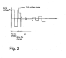
- Figure 2 shows a schematic of the lamp voltage waveform example (1) during starting of the lamp by a device of the invention for operating the discharge lamp;
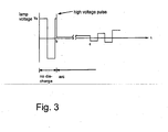
- Figure 3 shows a schematic of the lamp voltage waveform example (2) during starting of the lamp by a device of the invention for operating the discharge lamp;
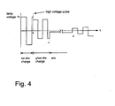
- Figure 4 shows a schematic of the lamp voltage waveform example (3) during starting of the lamp by a device of the invention for operating the discharge lamp;
- Figure 5 shows a schematic of the lamp voltage waveform example (4) during starting of the lamp by a device of the invention for operating the discharge lamp
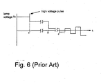
- Figure 6 shows a schematic of a voltage waveform example in the case of starting a discharge lamp by a conventional DC voltage.
- Figure 1 is a schematic of one embodiment of a device of the invention for operating a high pressure discharge lamp.
- Figure 1 shows the arrangement of a lighting circuit using a full bridge circuit. However, a half bridge circuit or a push-pull circuit can also be used.
- the circuit in this embodiment is connected to a voltage reduction chopper circuit 1 which is supplied with a DC voltage, and also to the output side of the voltage reduction chopper circuit 1; it comprises a full bridge circuit 2 which converts the DC voltage into a voltage with rectangular waves, and of an igniter device 3 which when the lamp is started produces a high voltage pulse.
- An AC voltage with rectangular waves or a DC voltage which is output by the full bridge circuit 2 is applied to the discharge lamp 4.
- a bypass capacitor Cp is connected parallel to the output side of the full bridge circuit 2 and bridges the high voltage pulse which is produced by the igniter device 3.
- control circuit 10 for controlling the voltage reduction chopper circuit 1 and the igniter device 3, and a full bridge driver circuit 11 for driving the full bridge circuit 2.
- a silica glass discharge lamp is filled with at least 0.15 mg/mm 3 mercury.
- the discharge lamp 4 is, for example, an ultra-high pressure discharge lamp of the short arc type in which a pair of electrodes is located opposite.
- the discharge lamp described below can be used:
- the voltage reduction chopper circuit 1 includes a switching device Q1 which carries out switching controlled by the output of the control circuit 10, a diode D1, an inductance L1, and a capacitor C1.
- the output voltage V L of the voltage reduction chopper circuit and the output current I L which is determined by the determination resistor R are supplied to the terminal Vin for determination of the voltage and the terminal Iin for determining the current of the control circuit 10.
- the control circuit 10 controls the ON/OFF ratio of the switching device Q1 and, via the full bridge circuit 2, controls the current or the wattage which is supplied to the discharge lamp 4.
- the control circuit 10 has a power controller 10a, a current limiter part 10b, a timer 10c and an evaluation part 10d which outputs a changeover signal to the full bridge driver circuit. If, during starting of the discharge lamp 4, a transition to an arc discharge takes place, the current supplied to the discharge lamp 4 is limited by the current limiter part 10b to a constant value.
- the wattage supplied to the discharge lamp 4 is determined, and control is exercised in such a way that the wattage supplied to the discharge lamp reaches the desired value.
- the full bridge circuit 2 includes the switching devices Q2 to Q5 which are connected in the manner of a bridge, and which are composed of transistors, such as FETs or the like, and of diodes D2 to D5 which are connected anti-parallel to these switching devices Q2 to Q5.
- the full bridge driver circuit 11 based on the changeover signal given by the evaluation part 10d of the control circuit 10, drives the switching devices Q2 to Q5, and the discharge lamp 4, when starting, carries an AC voltage with rectangular waves, after the transition from the glow discharge into the arc discharge, carries a DC voltage, and in the steady operating state, carries an AC voltage with rectangular waves.
- an AC voltage with a rectangular waveform of a few 10 Hz to a few hundred Hz is output by the full bridge circuit 2 first to the lamp.
- the evaluation part 10d of the control circuit 10 when the discharge lamp starts, sets the above described changeover signal to the first AC output signal.
- the full bridge driver circuit 11 alternatingly turns on the switching devices Q2, Q5 and the switching devices Q4 and Q5 such that the full bridge circuit 2 produces rectangular alternating waves with the above described frequency.
- an AC voltage with rectangular waves is applied to the discharge lamp 4.
- the control circuit 10 outputs a signal to an igniter device 3 which is synchronized to the polarity of the above described AC voltage.
- An igniter voltage, from the igniter device 3, at the above described polarity of the AC voltage superimposes a high voltage pulse on the AC voltage with rectangular waves and applies it.
- the duration of the above described glow discharge is 10 microseconds to 1 second (for example, roughly 2.5 ms).
- the lamp voltage decreases. If the state of the discharge lamp 4 passes into an arc discharge, the lamp voltage decreases. If the voltage applied to the terminal Vin for determining the voltage of the control circuit 10 falls below a given voltage, for example, 50 V, the evaluation part 10d of the control circuit 10 changes the changeover signal which is output to the full bridge driver circuit 11 into a DC output signal.
- the full bridge driver circuit 11 keeps the switching devices Q2 and Q5 or the switching devices Q4 and Q3 in the ON state so that the full bridge circuit 2 produces a DC output. In this way the a DC voltage is supplied to the discharge lamp 4.
- the polarity of the DC voltage is made the polarity in the transition into the arc discharge, the arc discharge state can be maintained more reliably.
- the evaluation part 10d of the control circuit 10 changes the above described changeover signal into a second AC output signal.
- the full bridge driver circuit 11 triggers the switching devices Q2 to Q5 such that the full bridge circuit 2 produces an AC output.
- the changeover into the above described AC output signal takes place by the timer 10c which is located in the control circuit 10.
- the timer 10c of the control circuit 10 starts timing when a DC voltage is applied to the discharge lamp 4. If a preset time, for example roughly 3 seconds, passes, the above described changeover signal is changed into a second AC output signal.
- the time for application of the above described direct current is 1 second to 5 seconds (for example, 3 seconds).
- the adjustment time of the timer 10c is set at, for example, 3 seconds, the voltage supplied to the discharge lamp 4 can be changed from direct current into alternating current.
- the full bridge driver circuit 11 When the above described changeover signal is delivered to the full bridge driver circuit 11, the full bridge driver circuit 11 turns on the switching devices Q2, Q5 and the switching devices Q4, Q5 in alternation, such that the full bridge circuit 2 produces rectangular alternating waves with the above described frequency and applies a rectangular AC voltage to the discharge lamp 4.
- the frequency of the AC voltage with rectangular waves is 60 Hz to 1000 Hz (for example, 200 Hz).
- the discharge lamp 4 passes into alternating current operation and reaches a steady operating state.
- the time starting from the arc discharge to the transition into steady-state operation is 10 seconds to 60 seconds (for example, 45 seconds).
- the full bridge circuit 2 can be subjected to alternating current operation when the voltage applied to the terminal Vin for determining the voltage of the control circuit 10 exceeds a given voltage, for example, 25 V.
- the frequency of the AC voltage which is supplied to the discharge lamp 4 in a glow discharge is fixed higher than that of the AC voltage which is supplied during steady-state operation, the interval during which the glow discharge continues can be shortened even if during cathode operation of the electrode (with a small amount of adhesion of the mercury) the discharge is started and even if in this way a glow discharge forms.
- the upper limit of the frequency of the AC voltage which is supplied in the glow discharge to the discharge lamp 4 is roughly 2 kHz.
- the AC voltage can be applied again to the discharge lamp and the starting process repeated.
- Figure 2 shows a lamp voltage waveform example [1] during lamp starting by the device for operation of discharge lamp in this embodiment.
- Figure 2 shows the situation in which a high voltage pulse has formed and a glow discharge has occurred when the electrode with a small amount of mercury adhesion has a negative polarity.
- a glow discharge forms, once before or after inverting the polarity, lamp extinction occurs once, and furthermore re-ignition of the discharge with reversed polarity takes place.
- the discharge formed by this re-ignition immediately passes into an arc discharge because the electrode with a large amount of mercury adhering is the cathode.
- the control circuit 10 in this embodiment determines the reduction of the lamp voltage, as was described above, fixes the polarity during the interval from b to c and at c again carries out a transition into operation with alternating current. Afterwards, the discharge lamp 4 continues AC operation until a steady state is reached.
- the formation time of the glow discharge when the discharge lamp starts is shortened to less than that or equal to the half period of the alternating current by the device of the invention for operating a discharge lamp. Sputtering of the electrode by the glow discharge is suppressed and an advantageous light flux maintenance characteristic is achieved.
- Figure 3 shows a lamp voltage waveform example [2] during lamp starting by the device for operation of discharge lamp in this embodiment.
- Figure 3 illustrates the situation in which a high voltage pulse has formed and at b an arc discharge has rapidly occurred when the electrode with a large amount of mercury adhesion has a negative polarity.
- the control circuit 10, in this embodiment determines the reduction of the lamp voltage, carries out direct current operation during the interval from b to c, at c carries out the transition into alternating current operation and afterwards reaches steady-state operation.
- the electrode with a large amount of adhesion of mercury has a negative polarity, as in this example, in practice a glow discharge does not occur, and it can be maintained that there is passage through an ideal starting process.
- Figure 4 shows a lamp voltage waveform example [3] for lamp starting by the device for operating the discharge lamp in this embodiment.
- Figure 4 shows the situation in which by a high voltage pulse which has formed at b a glow discharge occurs and that after the next inversion of polarity the glow discharge was still maintained, even if the voltage is lower than in the first glow discharge.
- the voltage is, for example, at least 50 V in a glow discharge after the polarity inversion, this is the situation in which the control circuit 10 of this embodiment has continued alternating current operation and after alternating current operation with a few periods a transition into an arc discharge has taken place at c.
- the control circuit 10 determines the reduction in the voltage in the transition into the arc discharge, carries out the transition into direct current operation and after a given time has passed, carries out a transition into alternating current operation at d.
- Figure 5 shows a lamp voltage waveform example [4] for lamp starting by the device for operating the discharge lamp in this embodiment.
- Figure 5 shows a case in which a glow discharge has occurred by the high voltage pulse which has formed at b, after the next inversion of polarity the glow discharge was still maintained even if the voltage is lower than in the first glow discharge, and after polarity inversion at c immediately before the next polarity inversion a transition into an arc discharge has taken place.
- the control circuit 10 determines the reduction of the voltage in the transition into an arc discharge and carries out a transition into direct current operation. However, since immediately before polarity inversion the transition into an arc discharge has taken place, the fixing to a DC voltage with a polarity which differs from the polarity at which the transition into the arc discharge took place is carried out by control delay. In this operation, no problems arise even if the arc discharge is maintained unchanged.
- Figure 6 shows the voltage waveform in the case of starting of the discharge lamp by a DC voltage by the prior art. That is, Figure 6 illustrates the situation in which the polarity of the DC voltage of the electrode with a small amount of mercury adhering is negative, a high voltage pulse forms and a glow discharge occurs for a, as is identical to the case shown in Figure 2 . Afterwards, however, the glow discharge continues over an interval of ten and a few ms, i.e. from a' to b', since the polarity is not inverted. The glow discharge which prevails over such a long time sputters the electrode and reduces the light flux.
- the glow discharge when the lamp starts can be reduced to a relatively short time and the blackening of the lamp by sputtering can be reduced. Therefore the light flux maintenance characteristic can be improved.
- a high pressure discharge lamp with greater than or equal to 0.15 mg/mm 3 mercury added in a projector device of the projection type, in which the mercury adhering to the two electrodes is not the same (as a result of cooling, deviation of the electrode position and the like), the formation time of the glow discharge can be effectively shortened.
Landscapes
- Circuit Arrangements For Discharge Lamps (AREA)
Claims (2)
- Vorrichtung zum Betrieb einer Hochdruckentladungslampe, die Folgendes umfasst: eine Hochdruckentladungslampe mit einem Silicaglas-Entladungsgefäß, das mit mindestens 0,15 mg/mm3 Quecksilber gefüllt ist und in dem ein Paar gegenüber liegender Elektroden angeordnet ist, und eine Einspeisungsvorrichtung, die die Entladungslampe mit einem Entladungsstrom versorgt, wobei die Einspeisungsvorrichtung ein Mittel zum Anlegen einer Wechselspannung an die Entladungslampe während einer Glimmentladung beim Starten der Lampe umfasst,
dadurch gekennzeichnet, dass
die Wechselspannung während der Glimmentladung mit einer Frequenz angelegt wird, die größer oder gleich der Frequenz der während des Dauerbetriebs angelegten Wechselspannung ist,
dass der obere Grenzwert der Frequenz der Wechselspannung, die an die Lampe in Glimmentladung angelegt wird, annähernd 2 kHz ist,
und dass das Mittel zum Anlegen der Wechselspannung zum Anlegen einer Gleichspannung während einer bestimmten Zeit an die Entladungslampe nach einem Übergang von der Glimmentladung in eine Bogenentladung und nach Ablauf der bestimmten Zeit geeignet ist, um an die Entladungslampe eine Wechselspannung anzulegen. - Vorrichtung zum Betrieb einer Hochdruckentladungslampe gemäß Anspruch 1, wobei die Einspeisungsvorrichtung einen Hochspannungsimpuls zum Starten der Entladungslampe nur bei einer bestimmten Polarität der Wechselspannung bereitstellt.
Applications Claiming Priority (2)
| Application Number | Priority Date | Filing Date | Title |
|---|---|---|---|
| JP2002193502 | 2002-07-02 | ||
| JP2002193502A JP4052039B2 (ja) | 2002-07-02 | 2002-07-02 | 高圧放電ランプ点灯装置 |
Publications (2)
| Publication Number | Publication Date |
|---|---|
| EP1379112A1 EP1379112A1 (de) | 2004-01-07 |
| EP1379112B1 true EP1379112B1 (de) | 2009-06-03 |
Family
ID=29720254
Family Applications (1)
| Application Number | Title | Priority Date | Filing Date |
|---|---|---|---|
| EP03014116A Expired - Lifetime EP1379112B1 (de) | 2002-07-02 | 2003-06-23 | Vorrichtung zum Betrieb einer Hochdruck-Entladungslampe |
Country Status (5)
| Country | Link |
|---|---|
| US (1) | US6888321B2 (de) |
| EP (1) | EP1379112B1 (de) |
| JP (1) | JP4052039B2 (de) |
| CN (1) | CN100456905C (de) |
| DE (1) | DE60327827D1 (de) |
Families Citing this family (22)
| Publication number | Priority date | Publication date | Assignee | Title |
|---|---|---|---|---|
| JP4273834B2 (ja) * | 2003-05-13 | 2009-06-03 | ウシオ電機株式会社 | 交流点灯方式の超高圧水銀ランプの点灯装置および点灯方法 |
| US7023144B2 (en) * | 2004-03-18 | 2006-04-04 | Ushiodenki Kabushiki Kaisha | Device for operation of a high pressure discharge lamp |
| EP1719056A4 (de) | 2004-08-26 | 2009-04-08 | Availigent Inc | Verfahren und system zur bereitstellung hoher verfügbarkeit für computeranwendungen |
| US7982405B2 (en) | 2005-03-22 | 2011-07-19 | Lightech Electronic Industries Ltd. | Igniter circuit for an HID lamp |
| US20100264848A1 (en) * | 2005-06-24 | 2010-10-21 | Koninklijke Philips Electronics, N.V. | Method of shutting down a high pressure discharge lamp and driving unit for driving a high pressure discharge lamp |
| JP4802581B2 (ja) * | 2005-07-15 | 2011-10-26 | パナソニック電工株式会社 | 放電灯点灯装置および画像表示装置 |
| JP4961724B2 (ja) * | 2005-11-24 | 2012-06-27 | ウシオ電機株式会社 | 放電ランプ点灯装置 |
| KR101358178B1 (ko) * | 2006-12-13 | 2014-02-07 | 오스람 게엠베하 | 방전 램프들 동작을 위한 회로 어렌지먼트, 및 상기 방전 램프들을 동작시키기 위한 방법 |
| KR20100005241A (ko) * | 2007-05-07 | 2010-01-14 | 오스람 게젤샤프트 미트 베쉬랭크터 하프퉁 | 고압 방전 램프들을 점화시키고 시동시키기 위한 방법 |
| JP4475296B2 (ja) | 2007-06-29 | 2010-06-09 | セイコーエプソン株式会社 | 点灯制御装置、光源装置、プロジェクタ及び点灯制御方法 |
| JP4470985B2 (ja) * | 2007-09-28 | 2010-06-02 | セイコーエプソン株式会社 | 光源装置、及びプロジェクタ |
| EP2222140A4 (de) * | 2007-11-20 | 2015-07-08 | Murata Manufacturing Co | Beleuchtungsvorrichtung mit einer hochdruckentladungslampe |
| JP5129652B2 (ja) * | 2008-05-27 | 2013-01-30 | パナソニック株式会社 | 放電灯点灯装置 |
| JP5277915B2 (ja) | 2008-12-03 | 2013-08-28 | セイコーエプソン株式会社 | 点灯装置、光源装置、プロジェクタ及び放電灯の点灯方法 |
| JP5601439B2 (ja) * | 2009-02-09 | 2014-10-08 | セイコーエプソン株式会社 | 放電灯点灯装置、放電灯の駆動方法及びプロジェクター |
| CN101553068B (zh) * | 2009-05-11 | 2013-06-05 | 浙江大学 | 简单可控时序脉冲式点火电路的控制方法及控制装置 |
| US8115403B2 (en) | 2009-08-18 | 2012-02-14 | Osram Sylvania Inc. | Method of starting an HID lamp and ballast incorporating same |
| JP5756761B2 (ja) * | 2010-02-10 | 2015-07-29 | Lumiotec株式会社 | 有機el照明装置 |
| JP6034312B2 (ja) * | 2011-03-10 | 2016-11-30 | コーニンクレッカ フィリップス エヌ ヴェKoninklijke Philips N.V. | ガス放電ランプを駆動する方法 |
| JP6055170B2 (ja) * | 2011-06-15 | 2016-12-27 | セイコーエプソン株式会社 | 光源装置、放電灯の駆動方法およびプロジェクター |
| CN102892246B (zh) * | 2011-07-18 | 2016-01-27 | 台达电子企业管理(上海)有限公司 | 放电灯系统及其控制方法 |
| CN111929290A (zh) * | 2019-05-13 | 2020-11-13 | 中国科学院上海硅酸盐研究所 | 钨丝电热蒸发-大气压辉光放电原子发射光谱装置 |
Family Cites Families (8)
| Publication number | Priority date | Publication date | Assignee | Title |
|---|---|---|---|---|
| GB2073944B (en) * | 1980-02-20 | 1985-02-06 | Mitsubishi Electric Corp | High pressure discharge lamp |
| JPH0665175B2 (ja) | 1985-07-25 | 1994-08-22 | 松下電工株式会社 | 放電灯点灯装置 |
| US5932976A (en) * | 1997-01-14 | 1999-08-03 | Matsushita Electric Works R&D Laboratory, Inc. | Discharge lamp driving |
| JP3418905B2 (ja) * | 1997-11-28 | 2003-06-23 | 三菱電機株式会社 | 高圧放電灯点灯装置 |
| US6020691A (en) * | 1999-04-30 | 2000-02-01 | Matsushita Electric Works R & D Laboratory, Inc. | Driving circuit for high intensity discharge lamp electronic ballast |
| KR100729877B1 (ko) * | 2000-04-20 | 2007-06-18 | 코닌클리즈케 필립스 일렉트로닉스 엔.브이. | 고압 가스 방전 램프를 점화 및 급전하는 밸러스트 |
| US6674249B1 (en) * | 2000-10-25 | 2004-01-06 | Advanced Lighting Technologies, Inc. | Resistively ballasted gaseous discharge lamp circuit and method |
| JP2003092198A (ja) * | 2001-09-18 | 2003-03-28 | Ushio Inc | 光源装置 |
-
2002
- 2002-07-02 JP JP2002193502A patent/JP4052039B2/ja not_active Expired - Lifetime
-
2003
- 2003-06-23 EP EP03014116A patent/EP1379112B1/de not_active Expired - Lifetime
- 2003-06-23 DE DE60327827T patent/DE60327827D1/de not_active Expired - Lifetime
- 2003-06-24 US US10/601,555 patent/US6888321B2/en not_active Expired - Lifetime
- 2003-07-02 CN CNB03148137XA patent/CN100456905C/zh not_active Expired - Fee Related
Also Published As
| Publication number | Publication date |
|---|---|
| CN100456905C (zh) | 2009-01-28 |
| JP4052039B2 (ja) | 2008-02-27 |
| US20040004448A1 (en) | 2004-01-08 |
| DE60327827D1 (de) | 2009-07-16 |
| CN1476284A (zh) | 2004-02-18 |
| JP2004039391A (ja) | 2004-02-05 |
| US6888321B2 (en) | 2005-05-03 |
| EP1379112A1 (de) | 2004-01-07 |
Similar Documents
| Publication | Publication Date | Title |
|---|---|---|
| EP1379112B1 (de) | Vorrichtung zum Betrieb einer Hochdruck-Entladungslampe | |
| EP1901589A1 (de) | Startvorrichtung für eine Hochdruckentladungslampe und Automobilscheinwerfer-Vorrichtung | |
| KR100664335B1 (ko) | 회로 장치 | |
| JP4171285B2 (ja) | 高圧放電灯の点灯方法および点灯装置 | |
| US6172468B1 (en) | Method and apparatus for igniting a gas discharge lamp | |
| EP0595414B1 (de) | Vorschaltgerät für eine Hochleistungsentladungslampe | |
| US7358686B2 (en) | Method and device for driving a gas discharge lamp | |
| US6323604B1 (en) | Circuit arrangement, an assigned electrical system and a discharge lamp with such a circuit arrangement, and a method for operating it | |
| US6815910B2 (en) | Device for operating a high pressure discharge lamp | |
| JP4438617B2 (ja) | 高圧放電ランプ用給電装置 | |
| EP2111084B1 (de) | Stroboskopische Hochdruckendladungslampe | |
| EP1472912B1 (de) | Einrichtung und verfahren zur steuerung einer gasentladungslampe und beleuchtungssystem mit gasentladungslampe und steuereinrichtung | |
| US6667587B1 (en) | Flickering mode control system for a high intensity discharge lamp | |
| JP2010525537A (ja) | ガス放電ランプ用のドライブ装置 | |
| JP4460106B2 (ja) | 高圧放電ランプの点灯方法 | |
| US7045972B2 (en) | Lighting method of ultra-high pressure mercury lamp | |
| JP2001307896A (ja) | 高圧放電ランプの点灯方法及び点灯装置 | |
| JP2003133096A (ja) | 放電灯点灯装置 | |
| JPH08222380A (ja) | 自動車用高輝度放電灯点灯装置 | |
| JP4211028B2 (ja) | 高圧放電ランプ点灯装置 | |
| JPH0582271A (ja) | 放電ランプ点灯装置 | |
| JP2005310678A (ja) | 放電灯点灯装置及び照明器具 | |
| US7990069B2 (en) | Method and circuit for driving a gas discharge lamp | |
| JP2002352972A (ja) | 放電灯点灯装置 | |
| JP2007188908A (ja) | 高圧放電灯点灯装置 |
Legal Events
| Date | Code | Title | Description |
|---|---|---|---|
| PUAI | Public reference made under article 153(3) epc to a published international application that has entered the european phase |
Free format text: ORIGINAL CODE: 0009012 |
|
| 17P | Request for examination filed |
Effective date: 20031002 |
|
| AK | Designated contracting states |
Kind code of ref document: A1 Designated state(s): AT BE BG CH CY CZ DE DK EE ES FI FR GB GR HU IE IT LI LU MC NL PT RO SE SI SK TR |
|
| AX | Request for extension of the european patent |
Extension state: AL LT LV MK |
|
| AKX | Designation fees paid |
Designated state(s): DE GB NL |
|
| GRAP | Despatch of communication of intention to grant a patent |
Free format text: ORIGINAL CODE: EPIDOSNIGR1 |
|
| GRAS | Grant fee paid |
Free format text: ORIGINAL CODE: EPIDOSNIGR3 |
|
| GRAA | (expected) grant |
Free format text: ORIGINAL CODE: 0009210 |
|
| AK | Designated contracting states |
Kind code of ref document: B1 Designated state(s): DE GB NL |
|
| REG | Reference to a national code |
Ref country code: GB Ref legal event code: FG4D |
|
| REF | Corresponds to: |
Ref document number: 60327827 Country of ref document: DE Date of ref document: 20090716 Kind code of ref document: P |
|
| PLBE | No opposition filed within time limit |
Free format text: ORIGINAL CODE: 0009261 |
|
| STAA | Information on the status of an ep patent application or granted ep patent |
Free format text: STATUS: NO OPPOSITION FILED WITHIN TIME LIMIT |
|
| 26N | No opposition filed |
Effective date: 20100304 |
|
| PGFP | Annual fee paid to national office [announced via postgrant information from national office to epo] |
Ref country code: GB Payment date: 20140618 Year of fee payment: 12 |
|
| PGFP | Annual fee paid to national office [announced via postgrant information from national office to epo] |
Ref country code: DE Payment date: 20140618 Year of fee payment: 12 Ref country code: NL Payment date: 20140510 Year of fee payment: 12 |
|
| REG | Reference to a national code |
Ref country code: DE Ref legal event code: R119 Ref document number: 60327827 Country of ref document: DE |
|
| GBPC | Gb: european patent ceased through non-payment of renewal fee |
Effective date: 20150623 |
|
| REG | Reference to a national code |
Ref country code: NL Ref legal event code: MM Effective date: 20150701 |
|
| PG25 | Lapsed in a contracting state [announced via postgrant information from national office to epo] |
Ref country code: DE Free format text: LAPSE BECAUSE OF NON-PAYMENT OF DUE FEES Effective date: 20160101 Ref country code: NL Free format text: LAPSE BECAUSE OF NON-PAYMENT OF DUE FEES Effective date: 20150701 Ref country code: GB Free format text: LAPSE BECAUSE OF NON-PAYMENT OF DUE FEES Effective date: 20150623 |