EP1378465A1 - Fördereinrichtung - Google Patents
Fördereinrichtung Download PDFInfo
- Publication number
- EP1378465A1 EP1378465A1 EP03014737A EP03014737A EP1378465A1 EP 1378465 A1 EP1378465 A1 EP 1378465A1 EP 03014737 A EP03014737 A EP 03014737A EP 03014737 A EP03014737 A EP 03014737A EP 1378465 A1 EP1378465 A1 EP 1378465A1
- Authority
- EP
- European Patent Office
- Prior art keywords
- engagement
- profile
- conveyor device
- conveyor
- arrangement
- Prior art date
- Legal status (The legal status is an assumption and is not a legal conclusion. Google has not performed a legal analysis and makes no representation as to the accuracy of the status listed.)
- Granted
Links
- 230000008878 coupling Effects 0.000 claims description 15
- 238000010168 coupling process Methods 0.000 claims description 15
- 238000005859 coupling reaction Methods 0.000 claims description 15
- 239000000463 material Substances 0.000 claims description 9
- 229910052751 metal Inorganic materials 0.000 claims description 4
- 239000002184 metal Substances 0.000 claims description 4
- 229910052782 aluminium Inorganic materials 0.000 claims description 3
- XAGFODPZIPBFFR-UHFFFAOYSA-N aluminium Chemical compound [Al] XAGFODPZIPBFFR-UHFFFAOYSA-N 0.000 claims description 3
- 230000009471 action Effects 0.000 claims description 2
- 239000000969 carrier Substances 0.000 description 10
- 238000012545 processing Methods 0.000 description 5
- 230000008901 benefit Effects 0.000 description 3
- 230000008859 change Effects 0.000 description 3
- 238000012546 transfer Methods 0.000 description 3
- 230000003111 delayed effect Effects 0.000 description 2
- 238000013461 design Methods 0.000 description 2
- 238000011161 development Methods 0.000 description 2
- 238000004519 manufacturing process Methods 0.000 description 2
- 238000003860 storage Methods 0.000 description 2
- 238000005299 abrasion Methods 0.000 description 1
- 238000013459 approach Methods 0.000 description 1
- 210000001520 comb Anatomy 0.000 description 1
- 238000010276 construction Methods 0.000 description 1
- 230000003292 diminished effect Effects 0.000 description 1
- 238000007599 discharging Methods 0.000 description 1
- 230000002349 favourable effect Effects 0.000 description 1
- 239000002783 friction material Substances 0.000 description 1
- 230000002401 inhibitory effect Effects 0.000 description 1
- 230000010354 integration Effects 0.000 description 1
- 238000003825 pressing Methods 0.000 description 1
- 230000003134 recirculating effect Effects 0.000 description 1
- 125000006850 spacer group Chemical group 0.000 description 1
- 238000009987 spinning Methods 0.000 description 1
- 230000003068 static effect Effects 0.000 description 1
- 239000000725 suspension Substances 0.000 description 1
- 238000012549 training Methods 0.000 description 1
- 230000007704 transition Effects 0.000 description 1
Images


Classifications
-
- B—PERFORMING OPERATIONS; TRANSPORTING
- B65—CONVEYING; PACKING; STORING; HANDLING THIN OR FILAMENTARY MATERIAL
- B65G—TRANSPORT OR STORAGE DEVICES, e.g. CONVEYORS FOR LOADING OR TIPPING, SHOP CONVEYOR SYSTEMS OR PNEUMATIC TUBE CONVEYORS
- B65G17/00—Conveyors having an endless traction element, e.g. a chain, transmitting movement to a continuous or substantially-continuous load-carrying surface or to a series of individual load-carriers; Endless-chain conveyors in which the chains form the load-carrying surface
- B65G17/20—Conveyors having an endless traction element, e.g. a chain, transmitting movement to a continuous or substantially-continuous load-carrying surface or to a series of individual load-carriers; Endless-chain conveyors in which the chains form the load-carrying surface comprising load-carriers suspended from overhead traction chains
-
- B—PERFORMING OPERATIONS; TRANSPORTING
- B65—CONVEYING; PACKING; STORING; HANDLING THIN OR FILAMENTARY MATERIAL
- B65G—TRANSPORT OR STORAGE DEVICES, e.g. CONVEYORS FOR LOADING OR TIPPING, SHOP CONVEYOR SYSTEMS OR PNEUMATIC TUBE CONVEYORS
- B65G17/00—Conveyors having an endless traction element, e.g. a chain, transmitting movement to a continuous or substantially-continuous load-carrying surface or to a series of individual load-carriers; Endless-chain conveyors in which the chains form the load-carrying surface
- B65G17/002—Conveyors having an endless traction element, e.g. a chain, transmitting movement to a continuous or substantially-continuous load-carrying surface or to a series of individual load-carriers; Endless-chain conveyors in which the chains form the load-carrying surface comprising load carriers resting on the traction element
-
- B—PERFORMING OPERATIONS; TRANSPORTING
- B65—CONVEYING; PACKING; STORING; HANDLING THIN OR FILAMENTARY MATERIAL
- B65G—TRANSPORT OR STORAGE DEVICES, e.g. CONVEYORS FOR LOADING OR TIPPING, SHOP CONVEYOR SYSTEMS OR PNEUMATIC TUBE CONVEYORS
- B65G17/00—Conveyors having an endless traction element, e.g. a chain, transmitting movement to a continuous or substantially-continuous load-carrying surface or to a series of individual load-carriers; Endless-chain conveyors in which the chains form the load-carrying surface
- B65G17/22—Conveyors having an endless traction element, e.g. a chain, transmitting movement to a continuous or substantially-continuous load-carrying surface or to a series of individual load-carriers; Endless-chain conveyors in which the chains form the load-carrying surface with oppositely-moving parts of the conveyor located in a common plane and being formed by individual load carriers only
-
- B—PERFORMING OPERATIONS; TRANSPORTING
- B65—CONVEYING; PACKING; STORING; HANDLING THIN OR FILAMENTARY MATERIAL
- B65G—TRANSPORT OR STORAGE DEVICES, e.g. CONVEYORS FOR LOADING OR TIPPING, SHOP CONVEYOR SYSTEMS OR PNEUMATIC TUBE CONVEYORS
- B65G19/00—Conveyors comprising an impeller or a series of impellers carried by an endless traction element and arranged to move articles or materials over a supporting surface or underlying material, e.g. endless scraper conveyors
- B65G19/02—Conveyors comprising an impeller or a series of impellers carried by an endless traction element and arranged to move articles or materials over a supporting surface or underlying material, e.g. endless scraper conveyors for articles, e.g. for containers
-
- B—PERFORMING OPERATIONS; TRANSPORTING
- B65—CONVEYING; PACKING; STORING; HANDLING THIN OR FILAMENTARY MATERIAL
- B65G—TRANSPORT OR STORAGE DEVICES, e.g. CONVEYORS FOR LOADING OR TIPPING, SHOP CONVEYOR SYSTEMS OR PNEUMATIC TUBE CONVEYORS
- B65G21/00—Supporting or protective framework or housings for endless load-carriers or traction elements of belt or chain conveyors
- B65G21/20—Means incorporated in, or attached to, framework or housings for guiding load-carriers, traction elements or loads supported on moving surfaces
- B65G21/22—Rails or the like engaging sliding elements or rollers attached to load-carriers or traction elements
-
- B—PERFORMING OPERATIONS; TRANSPORTING
- B65—CONVEYING; PACKING; STORING; HANDLING THIN OR FILAMENTARY MATERIAL
- B65G—TRANSPORT OR STORAGE DEVICES, e.g. CONVEYORS FOR LOADING OR TIPPING, SHOP CONVEYOR SYSTEMS OR PNEUMATIC TUBE CONVEYORS
- B65G23/00—Driving gear for endless conveyors; Belt- or chain-tensioning arrangements
- B65G23/02—Belt- or chain-engaging elements
- B65G23/14—Endless driving elements extending parallel to belt or chain
-
- B—PERFORMING OPERATIONS; TRANSPORTING
- B65—CONVEYING; PACKING; STORING; HANDLING THIN OR FILAMENTARY MATERIAL
- B65G—TRANSPORT OR STORAGE DEVICES, e.g. CONVEYORS FOR LOADING OR TIPPING, SHOP CONVEYOR SYSTEMS OR PNEUMATIC TUBE CONVEYORS
- B65G2201/00—Indexing codes relating to handling devices, e.g. conveyors, characterised by the type of product or load being conveyed or handled
- B65G2201/02—Articles
Definitions
- the invention relates to a conveyor for transporting material to be conveyed with at least one profile rail, with at least one of the carried at least one profile rail and movable along this Conveyed goods carrier, and with one along at least one profile rail extending, drivable funding, the at least one Conveyed goods carrier has at least one engagement unit which with the Funding is in the carry-over or can be brought.
- Transfer systems are used, for example, in a production line for transporting workpieces between individual stations at which Processing or assembly operations take place.
- An example is the Catalog "Transfer system TS2" of Robert Bosch GmbH referenced.
- This transfer system is suitable for connecting manual workplaces due to its high positioning accuracy, it can also be used for automated assembly.
- the known system requires a powerful one Drive, as this is not only for driving the conveyed goods in the area the conveyor sections of the production line, but also for the Overcoming the weight of the workpieces and conveyed goods resulting static friction between the funding and the conveyed goods in the area of processing and assembly stations.
- the Conveyor goods can be moved longitudinally via rollers on a running rail supported.
- the running rail has a drive belt guide in which a friction belt is guided. With a friction surface of the conveyed goods carrier is in this friction belt non-positive entrainment.
- the conveyed goods carrier In the event of a jam, the conveyed goods carrier the frictional engagement of the conveyed goods carrier with the friction belt interrupted. Nevertheless, it is due to the relative movement between the friction belt and the material carrier to wear touching surfaces.
- DE 198 25 955 A1 discloses a third embodiment, which represents a combination of the first two exemplary embodiments and thus also has their disadvantages, in particular the disadvantage a not negligible wear of the drive device.
- the main disadvantage of the prior art is in the fact that there is a slowdown or stop of the conveyed goods to enable processing of the workpieces arranged on it to wear out for proper functioning of the Drive device particularly important drive means, for example Drive belt comes.
- this object is achieved by a generic conveyor solved, in which the engagement unit a by a storage unit encircling engagement element and in which also a Orbital movement influencing the engagement element, in particular inhibitory, clutch assembly is provided. That way No wear and tear when stopping or slowing down the conveyor on the functional areas of Funding vehicles and subsidies occur, but at the most for this specially provided coupling arrangement, for example then, if this comprises a friction arrangement.
- This friction arrangement can especially what their construction and the choice of used In terms of materials, their function as a slip clutch and Wear part can be optimized. If the clutch assembly on the other hand, has a magnetic coupling, the orbital movement of the Engagement elements can also be influenced almost without wear.
- friction clutch or magnetic clutch can an actuating arrangement can be provided, by means of which the amount of Influencing the circumferential movement of the engagement element is changeable.
- the actuating arrangement can apply the pressing force influence the friction arrangement against the circumferential engagement element.
- the actuating arrangement can extend of an air gap that change the two together magnetically separating interacting magnetic coupling parts.
- the actuator for an integrated wear adjustment to care.
- the actuator arrangement can effective use of the available space in a Circumferential plane of the engaging element is essentially orthogonal Act direction of action on the clutch assembly.
- the circumferential engagement element is designed as a circumferential band or chain. Is preferred you can use a wheel as a circumferential engagement element, however its storage structurally simple and its engagement with the Funding due to its essentially rigid or in comparison with a belt or chain more rigid training is more effective.
- Advantageous is also when the engaging element and the funding in a positive Take away intervention.
- this then requires precise coordination of the frictional forces between the engaging element and the funding on the one hand and the engaging element and clutch assembly on the other hand to ensure that when stopping or slowing down the material carrier, do this required relative movement actually between the engagement element and clutch assembly takes place. It is therefore particularly preferred the conveyor as a toothed belt and the engaging element accordingly as Train gear.
- At least one Profile rail has a guide section which with the bearing element is in leadership engagement.
- the guide section also acts resiliently the bearing element in order to keep it in engagement with the conveying means, so they can when stopping or slowing down the conveyor forces occurring between the conveyor and the engaging element at least partially diminished by this suspension. This affects the Wear of the engaging element and the conveyance means favorable.
- At least one profile rail at least has a guide recess for guiding the conveying means.
- At least one Profile rail has a sliding section on which the at least one Conveyed goods carrier rests.
- This sliding section can be a separate one trained slide bar include, for example, in a groove, is preferably held positively.
- the sliding section is one piece on the profile rail molded slide attachment is.
- the slide bar or Sliding section made of a low-friction material, so that the when conveying the conveyed goods along the profile rail from the weight originating and to be overcome by the drive device Frictional force between the conveyed goods carrier and the sliding section is only slight Has value.
- At least one Profile rail a guideway for at least one of the conveyed goods has assigned linear slide, with for example a roller guide or a recirculating ball bearing guide or a Ball roller arrangement can be used.
- At least one Profile rail has a return channel for the funding.
- the return channel can be omitted, for example, if the returning section of the funding passes work stations and is used to drive conveyed goods carriers.
- At least one profile rail is formed in several pieces is with at least one support profile and at least one guide profile.
- the support profile can be a light metal profile, preferably Aluminum profile, and the guide profile designed as a plastic profile his.
- the two profiles can, for example, by snapping the Plastic profile to be connected to the light metal profile.
- the guide profile formed from plastic can be the above mentioned management recesses for the funding and the Have guide section for the bearing element.
- the springy Press the bearing element against the funding by Guide section can, for example, by a plastic material inherent elasticity of the guide portion are provided.
- the use of one-piece rails is also conceivable.
- the engaging element at least along part of the conveyor line next to the funding can also be brought into engagement with an additional engagement arrangement.
- the additional engagement arrangement can be the simplest Execution be designed to be fixed, for example as a rack. Such a fixed additional engagement arrangement leads to a by their extension in the direction of movement of the conveyed goods carrier predetermined period of time for a constant change in speed of the conveyor.
- the additional engagement arrangement but also be designed as a circumferential engagement arrangement, for example as a toothed belt with a separate drive. With a circumferential additional engagement arrangement, the movement of the Conveyed goods accelerated in any desired manner and / or be delayed. Yes, it is even a reversal of the direction of movement of the Conveyor goods conceivable.
- the conveyor device according to the invention can also be used when table-like trained carriers are used on wengistens two profile rails rest, driven by a drive device are, the funding provided only on one of these rails is. This is particularly advantageous because it creates a Changing the width dimension of the conveyed goods carrier is not necessary also a change in width of the drive device must entail.
- curve sections and branches from the or Junctions into the main line without complex additional units, such as Roller curves, lifting cross units and the like can be realized.
- each carrier has at least two engagement elements, so can the discharge and infeed of a carrier from the or in the main route in a simple manner, in particular without the Use of additional drives can be realized as the drive devices of main and secondary line can be arranged so easily can that at any time at least one of the engaging elements with the funding of the main line or the secondary line in Intervention stands.
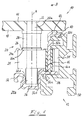
- a conveyor device is generally at 10 designated. It includes a profile rail 12, both for support and also for guiding a conveyor 14. Furthermore, the Profile rail 12 as a funding one not shown in detail Drive device a toothed belt 16 guided to drive the Conveyed goods carrier 14 is determined in the direction of movement B.
- the conveyed goods carrier 14 is table-like in the present exemplary embodiment formed and comprises a table top 18 on which the material to be conveyed, for example workpieces to be machined, attached or loosely arranged can be. Furthermore, the conveyed goods carrier 14 comprises an engagement unit 20, which is designed for engagement with the toothed belt 16. On a Axis 22 (axis direction A), whose upper end 22a on the plate 18th is fixed, a gear 24 is rotatably supported, the external teeth combs with the toothing of the toothed belt 16. A friction element 26 is by means of a spring arrangement 28 acting in the axial direction A against one Upper end face 24a of the gear 24 is biased and in with this Frictional engagement.
- the biasing force of the spring arrangement 28 is chosen such that the frictional forces between the friction element 26 and the gear 24 so great are that the spellgutlini 14 due to the meshing engagement of the Gear 24 with the toothed belt 16 normally from the toothed belt 16 is taken along without the gear 24 around the axis A turns.
- the movement of the conveyed goods carrier 14 is interrupted or accelerated compared to the movement of the toothed belt 16 or delayed, the gear 24 begins to roll on the toothed belt 16 and rotates against the frictional force between the friction element 26 and Gear 24 around the axis A.
- the gear 24 and that under the Biasing by the spring arrangement 28 standing friction element 26 thus act together as a slip clutch, which decouples the Movement of the toothed belt 16 and the conveyed goods carrier 14 enables.
- the gear 24 essentially rolls with its external toothing wear-free on the toothing of the toothed belt 16. wear takes place almost exclusively between to a considerable extent the gear 24 and the friction element 26 instead.
- Frictional end face 24a of the gear 24 either itself designed to be wear-resistant or with a wear-resistant friction lining can be provided.
- the wear takes place in the invention Conveyor device 10 on and specially provided for this purpose trained elements instead.
- the friction surface 26a of the friction element 26 and the end face 24a of the gear 24 or its friction lining with respect to the Axis A can be conical. A light one already ensures this Taper for self-centering of the meshed Friction surfaces with respect to the axis A. In the case of strong taper, this can be done in addition, the area available for frictional engagement is enlarged become.
- the profile rail 12 formed by two profiles, namely a support profile 30 and one Guide profile 32.
- the support profile 30 is preferably a light metal profile, For example, as an extruded aluminum profile, trained and ensures the required dimensional stability of the profile rail 12.
- the guide profile 32 on the other hand, for example, can be made of plastic.
- the leadership profile 32 has lugs 32a, 32b and 32c, by means of which it is form-fitting attached to the support profile 30 and locked with this.
- the two profiles 30 and 32 together form a return channel 34, in which is not the case with the gears 24 of conveyed goods carriers 14 in Engaging passive strand 16a of the toothed belt 16 is returned becomes.
- the guide profile 32 with a guide groove 36 with in Essentially U-shaped shape.
- the guide trough 36 represents the trajectory of the Conveyed goods carrier 14.
- the free leg 32d of the guide profile 32 is formed such that it resiliently against the bearing axis 22nd presses, whereby the gear 24 meshes with the Timing belt 16 is held.
- the guide profile 32 has a undercut groove 40 into which a slide bar 42 is inserted.
- a slide bar 42 On preferably from a low-friction and abrasion-resistant Material made slide bar 42 is the plate 18 of the conveyor 14 and slides along it.
- the guide profile 32 'with a sliding extension 42' is shown instead of the provision of a separate slide bar 42.
- guide tracks can also be provided on the guide profile 32 ′′ designed for carriages 44 arranged on the conveyed goods carrier or be arranged. In the embodiment shown in Fig. 3 these guideways 42 'are formed by running wires 46, which in the Guide profile 32 "are embedded. Furthermore, the carriage 44 in the illustrated embodiment rollers 48.
- a major advantage of the conveyor device 10 according to the invention is to see that in the operation of this conveyor 10 when the conveyed goods carriers move along the rail 12, only that Frictional force between the slide strips 42 and the table top 18 of the Conveyor carriers must be overcome while in the event of an interruption the movement of the conveyed goods carrier 14 only the frictional force overcome between the friction element 26 and the gear 24 are needed.
- the (not shown) drive device for the Toothed belt 16 can therefore be designed to perform poorly his.
- the gear wheel 24 stands along a section S not only with the toothing of the toothed belt 16 engaged, but also with the toothing of a rack 50. Through this additional toothing engagement, the gear 24 forcibly rotated about axis A so that it rolls on the toothed belt 16 against its direction of movement. Consequently, the conveyed goods carrier 14 is compared with the speed of the toothed belt 16 slows down.
- the conveyed goods carrier 14 can, but instead of the rack 50 a rotating one Toothed belt 52 are used, its direction of movement and Movement speed can be specified specifically.
- a suitable position and / or speed sensor system for the conveyor 14 can be a (not shown) control unit Activate the drive of the additional toothed belt 52 such that the desired direction and speed of movement of the winninggut lymphos 14 results.
- Such targeted influencing of Movement of the conveyed goods carrier 14 is advantageous if it is, for example is about the distance between consecutive conveyors to set a predetermined dimension or a conveyor for one to have a predetermined time arrive at a processing station.
- the table top 18 of the conveyed goods carrier 14 can rest on at least one other profile rail.
- This one more Profile rail does not necessarily also need one Toothed belt drive to be equipped and can therefore be one of the Profile rail 12 have different shapes.
- a big advantage of the fact that only one of these rails with a belt drive 16 needs to be equipped is that the Width of the conveyor 10 to the respective application in a simple manner Can be adjusted without changing the Drive device would require.
- the "one-sided" Drive concept in a simple way the integration of turnouts W to Feeding of conveyed goods carriers 14 into a main conveyor line H or for discharging conveyed goods carriers 14 from a main conveyor line H in a secondary conveyor line N.
- FIG. 7 shows a further embodiment of an inventive one Shown conveyor, which is essentially the 1 corresponds to the embodiment. Analog parts are in Fig. 7 therefore provided with the same reference numerals as in Fig. 1, however increases by the number 100. In addition, the embodiment 7 are described below only in so far as they are differs from the embodiment of FIG. 1, on the description thereof hereby otherwise expressly referred.
- the conveyor device 110 has a friction arrangement instead of one trained coupling device via a magnetic coupling device 126th
- the permanent magnet 162 holds.
- the Permanent magnets 162 are preferably all in the same Magnetic direction oriented, i.e. for example, the south poles of all Magnet 162 in the illustration according to FIG. 7 downwards.
- the number, Arrangement and magnetic orientation of the permanent magnet 162 correspond. That in a coupling position of the coupling device 126 there is an associated permanent magnet for each permanent magnet 162 164 opposite, with two magnets associated with each other poles of the same name so that they attract each other. This Attraction prevents the spinning of the Engagement elements 124.
- the attraction force can be given a predetermined assembly of the pane 160 and the engaging member 124 with magnets 162 and 164 through the Distance d between the disk 160 and the engagement element 124 changed or set.
- This distance can be either an adjusting device provided for this purpose can be influenced.
- a spacer 166 is also possible predetermined thickness d between the disc 160 and the engaging member 124 to be provided.
- a conveying device (10) for transporting conveyed goods comprises at least one profile rail (12), at least one of the at least a profile rail (12) carried and movable along this Goods carrier (14), and one along at least one profile rail (12) extending, drivable conveying means (16), the at least one Goods carrier (14) has at least one engagement unit (20) which stands or can be brought into engagement with the funding (16).
- the engagement unit (20) has a bearing unit (22) revolving engagement element (24), and furthermore is a revolving movement of the engaging element (24) influencing coupling arrangement (26) provided.
Landscapes
- Engineering & Computer Science (AREA)
- Mechanical Engineering (AREA)
- Chain Conveyers (AREA)
- Control Of Conveyors (AREA)
- Rollers For Roller Conveyors For Transfer (AREA)
- Intermediate Stations On Conveyors (AREA)
- Transmission Devices (AREA)
Abstract
Description
- Fig. 1
- eine orthogonal zur Bewegungsrichtung der Fördergutträger genommene Schnittansicht einer ersten Ausführungsform einer erfindungsgemäßen Fördereinrichtung;
- Fig. 2 und 3
- Ansichten ähnlich Fig. 1 weiterer erfindungsgemäßer Fördereinrichtungen;
- Fig. 4 bis 6
- schematische Draufsichten auf erfindungsgemäße Fördereinrichtungen zur Erläuterung von Ausführungsvarianten; und
- Fig. 7
- eine Ansicht ähnlich Fig. 1 einer weiteren Ausführungsform einer erfindungsgemäßen Fördereinrichtung.
Claims (24)
- Fördereinrichtung (10) zum Transport von Fördergut, umfassendwobei der wenigstens eine Fördergutträger (14) wenigstens eine Eingriffseinheit (20) aufweist, welche mit dem Fördermittel (16) in Mitnahmeeingriff steht oder bringbar ist,wenigstens eine Profilschiene (12),wenigstens einen von der wenigstens einen Profilschiene (12) getragenen und längs dieser bewegbaren Fördergutträger (14),ein sich längs wenigstens einer Profilschiene (12) erstreckendes, antreibbares Fördermittel (16),
dadurch gekennzeichnet,dass die Eingriffseinheit (20) ein um eine Lagereinheit (22) umlaufendes Eingriffselement (24) aufweist und dass ferner eine die Umlaufbewegung des Eingriffselements (24) beeinflussende Kupplungsanordnung (26) vorgesehen ist. - Fördereinrichtung nach Anspruch 1,
dadurch gekennzeichnet, dass die Kupplungsanordnung eine Reibanordnung (26) umfasst. - Fördereinrichtung nach Anspruch 1,
dadurch gekennzeichnet, dass die Kupplungsanordnung eine verschleißfreie Kupplung umfasst, beispielsweise eine Magnetkupplung (162/164). - Fördereinrichtung nach einem der vorhergehenden Ansprüche,
dadurch gekennzeichnet, dass eine Stellanordnung (28) vorgesehen ist, mittels derer der Betrag der Beeinflussung der Umlaufbewegung des Eingriffselements (24) veränderbar ist. - Fördereinrichtung nach Anspruch 4,
dadurch gekennzeichnet, dass die Stellanordnung eine Federanordnung umfasst. - Fördereinrichtung nach Anspruch 4 oder 5,
dadurch gekennzeichnet, dass die Stellanordnung (28) in einer zur Umlaufebene des Eingriffselements (24) im Wesentlichen orthogonal verlaufenden Wirkrichtung auf die Kupplungsanordnung (26) einwirkt. - Fördereinrichtung nach einem der vorhergehenden Ansprüche,
dadurch gekennzeichnet, dass das Eingriffselement (24) ein Rad ist. - Fördereinrichtung nach einem der vorhergehenden Ansprüche,
dadurch gekennzeichnet, dass das Eingriffselement (24) und das Fördermittel (16) in formschlüssigem Mitnahmeeingriff stehen. - Fördereinrichtung nach einem der vorhergehenden Ansprüche,
dadurch gekennzeichnet, dass wenigstens eine Profilschiene (12) einen Führungsabschnitt (36) aufweist, der mit der Lagereinheit (22) in Führungseingriff steht. - Fördereinrichtung nach Anspruch 9,
dadurch gekennzeichnet, dass der Führungsabschnitt (36) auf die Lagereinheit (22) federnd einwirkt und so das umlaufende Eingriffselement (24) in Eingriff mit dem Fördermittel (16) hält. - Fördereinrichtung nach einem der vorhergehenden Ansprüche,
dadurch gekennzeichnet, dass wenigstens eine Profilschiene (12) wenigstens eine Führungsausnehmung (38) zum Führen des Fördermittels (16) aufweist. - Fördereinrichtung nach einem der vorhergehenden Ansprüche,
dadurch gekennzeichnet, dass wenigstens eine Profilschiene (12) einen Gleitabschnitt (42; 42'; 42") aufweist, auf dem der wenigstens eine Fördergutträger (14) aufliegt. - Fördereinrichtung nach Anspruch 12,
dadurch gekennzeichnet, dass der Gleitabschnitt eine gesondert ausgebildete Gleitleiste (42) umfasst. - Fördereinrichtung nach Anspruch 12,
dadurch gekennzeichnet, dass der Gleitabschnitt ein an der Profilschiene (12) einstückig angeformter Gleitansatz (42') ist. - Fördereinrichtung nach einem der Ansprüche 1 bis 11,
dadurch gekennzeichnet, dass wenigstens eine Profilschiene (12) eine Führungsbahn (42") für wenigstens einen dem Fördergutträger (14) zugeordneten Linearschlitten (48) aufweist. - Fördereinrichtung nach einem der vorhergehenden Ansprüche,
dadurch gekennzeichnet, dass wenigstens eine Profilschiene (12) einen Rückführkanal (34) für das Fördermittel (16) aufweist. - Fördereinrichtung nach einem der vorhergehenden Ansprüche,
dadurch gekennzeichnet, dass wenigstens eine Profilschiene (12) mehrstückig ausgebildet ist mit wenigstens einem Tragprofil (30) und wenigstens einem Führungsprofil (32). - Fördereinrichtung nach Anspruch 17,
dadurch gekennzeichnet, dass das Tragprofil (30) als Leichtmetallprofil, vorzugsweise Aluminiumprofil, und das Führungsprofil (32) als Kunststoffprofil ausgebildet ist. - Fördereinrichtung nach Anspruch 17 oder 18,
dadurch gekennzeichnet, dass das Führungsprofil (32) auf das Tragprofil (30) aufrastbar ist. - Fördereinrichtung nach einem der vorhergehenden Ansprüche,
dadurch gekennzeichnet, dass das Eingriffselement (24), zumindest längs eines Teils der Förderstrecke neben dem Fördermittel (16) ferner mit einer zusätzlichen Eingriffsanordnung (50; 52) in Eingriff bringbar ist. - Fördereinrichtung nach Anspruch 20,
dadurch gekennzeichnet, dass die zusätzliche Eingriffsanordnung (50) feststehend ausgebildet ist. - Fördereinrichtung nach Anspruch 20,
dadurch gekennzeichnet, dass die zusätzliche Eingriffsanordnung (52) umlaufend ausgebildet ist. - Fördereinrichtung nach einem der vorhergehenden Ansprüche,
dadurch gekennzeichnet, dass jeder Fördergutträger (14) wenigstens zwei Eingriffselemente (20) aufweist. - Fördereinrichtung (#10) nach dem Oberbegriff des Anspruchs 1 und gewünschtenfalls dem Kennzeichen eines der Ansprüche 1 bis 23,
dadurch gekennzeichnet, dass die Eingriffseinheit ein am Fördergutträger federnd gelagertes Eingriffselement aufweist, dessen Mitnahmeeingriff mit dem Fördermittel aufgrund der federnden Lagerung aufhebbar ist.
Priority Applications (1)
| Application Number | Priority Date | Filing Date | Title |
|---|---|---|---|
| EP04027891A EP1538113B1 (de) | 2002-07-01 | 2003-06-27 | Fördereinrichtung |
Applications Claiming Priority (2)
| Application Number | Priority Date | Filing Date | Title |
|---|---|---|---|
| DE10229440A DE10229440A1 (de) | 2002-07-01 | 2002-07-01 | Fördereinrichtung |
| DE10229440 | 2002-07-01 |
Related Child Applications (2)
| Application Number | Title | Priority Date | Filing Date |
|---|---|---|---|
| EP04027891A Division EP1538113B1 (de) | 2002-07-01 | 2003-06-27 | Fördereinrichtung |
| EP04027891.3 Division-Into | 2004-11-24 |
Publications (2)
| Publication Number | Publication Date |
|---|---|
| EP1378465A1 true EP1378465A1 (de) | 2004-01-07 |
| EP1378465B1 EP1378465B1 (de) | 2005-09-28 |
Family
ID=29719420
Family Applications (2)
| Application Number | Title | Priority Date | Filing Date |
|---|---|---|---|
| EP03014737A Expired - Lifetime EP1378465B1 (de) | 2002-07-01 | 2003-06-27 | Fördereinrichtung |
| EP04027891A Expired - Lifetime EP1538113B1 (de) | 2002-07-01 | 2003-06-27 | Fördereinrichtung |
Family Applications After (1)
| Application Number | Title | Priority Date | Filing Date |
|---|---|---|---|
| EP04027891A Expired - Lifetime EP1538113B1 (de) | 2002-07-01 | 2003-06-27 | Fördereinrichtung |
Country Status (3)
| Country | Link |
|---|---|
| US (1) | US6962249B2 (de) |
| EP (2) | EP1378465B1 (de) |
| DE (3) | DE10229440A1 (de) |
Cited By (2)
| Publication number | Priority date | Publication date | Assignee | Title |
|---|---|---|---|---|
| EP2055655A4 (de) * | 2006-08-25 | 2012-02-29 | Tsubaki Yamakyu Chain Co Ltd | Fahrrahmenvorrichtung für eine fördereinrichtung |
| DE102016109351A1 (de) * | 2016-05-20 | 2017-11-23 | Markus Koppold | Werkstückträger und Stauförderer zum Einsatz desselben |
Families Citing this family (20)
| Publication number | Priority date | Publication date | Assignee | Title |
|---|---|---|---|---|
| DE10323910A1 (de) * | 2003-05-23 | 2005-01-05 | Siemens Ag | Kettenumlaufeinrichtung bzw. Bandumlaufeinrichtung und Verfahren zu deren Betrieb |
| DE102004019922A1 (de) | 2004-04-21 | 2004-11-18 | Bär, Ralf, Dipl.-Ing. | Fördersystem für Werkstücke oder Gegenstände |
| DE202005003883U1 (de) * | 2005-03-10 | 2006-04-27 | Storcon Gmbh | Vorrichtung zum Transport insbesondere von PET-Flaschen in hängender Position |
| US7063204B1 (en) | 2005-03-15 | 2006-06-20 | Seagate Technology Llc | Precision conveyor |
| DE102005041524A1 (de) * | 2005-08-31 | 2007-03-15 | Castero Gmbh & Co. Kg | Hängefördersystem |
| DE202008002097U1 (de) | 2008-02-14 | 2009-07-02 | Raw Tex International Ag | Schleppantrieb für Fahrzeuge |
| US8789684B2 (en) | 2010-04-19 | 2014-07-29 | Foodmate Bv | Rotatable article support for a conveyor |
| NL2004574C2 (en) | 2010-04-19 | 2011-10-20 | Foodmate B V | Rotatable article support for a conveyor. |
| WO2011133028A1 (en) * | 2010-04-19 | 2011-10-27 | Foodmate B.V. | Rotatable article support for a conveyor |
| NL2006075C2 (en) | 2011-01-26 | 2012-07-30 | Foodmate B V | Rotationally indexed article support for a conveyor system having an alignment station. |
| US8882571B2 (en) | 2011-01-26 | 2014-11-11 | Foodmate Bv | Method of deboning animal thighs for separating and collecting meat therefrom and apparatus for performing the method |
| US8267241B2 (en) | 2011-01-26 | 2012-09-18 | Foodmate Bv | Rotationally indexed article support for a conveyor system having an alignment station |
| WO2012102609A1 (en) | 2011-01-26 | 2012-08-02 | Foodmate B.V. | Method of deboning animal thighs for separating and collecting meat there from and apparatus for performing the method |
| CN102642697B (zh) * | 2012-05-09 | 2014-03-12 | 四川省原子能研究院 | 积放式悬挂输送机人字轨推头桥 |
| NL2009033C2 (en) | 2012-06-19 | 2013-12-23 | Foodmate B V | Weighing method and apparatus. |
| US8808068B2 (en) | 2012-10-29 | 2014-08-19 | Foodmate Bv | Method of and system for automatically removing meat from an animal extremity |
| NL2009718C2 (en) | 2012-10-29 | 2014-05-01 | Foodmate B V | Method of mechanically removing skin from animal parts. |
| US9132873B1 (en) | 2013-03-14 | 2015-09-15 | Kuka Systems Corporation North America | Flexible conveyance system |
| US9045183B2 (en) * | 2013-03-14 | 2015-06-02 | Kuka Systems Corporation North America | Flexible conveyance system |
| CN208252599U (zh) * | 2018-03-21 | 2018-12-18 | 梁顺伟 | 一种防侧翻的三节导轨 |
Citations (6)
| Publication number | Priority date | Publication date | Assignee | Title |
|---|---|---|---|---|
| GB601719A (en) * | 1946-06-04 | 1948-05-11 | King Ltd Geo W | Improvements in or relating to conveyor systems |
| DE3212224A1 (de) * | 1982-04-01 | 1983-10-13 | Sortimat Creuz & Co Gmbh, 7057 Winnenden | Transfermaschine, insbesondere fuer taktungebundenen betrieb |
| EP0623518A1 (de) * | 1993-05-06 | 1994-11-09 | Zweckform Etikettiertechnik Gesellschaft Mit Beschränkter Haftung | Vorrichtung zum wenigstens teilweisen Aufbringen von Etiketten auf Gegenstände |
| DE19517276A1 (de) * | 1995-05-11 | 1996-11-14 | Hoyer Montagetechnik Gmbh | Transfersystem für taktungebundenen Betrieb |
| US5735384A (en) * | 1996-08-29 | 1998-04-07 | Western Atlas, Inc. | Endless accumulating conveyor |
| DE19825955A1 (de) * | 1998-06-10 | 1999-12-23 | Wf Logistik Gmbh | Fördereinrichtung, insbesondere Hängefördereinrichtung, und zugehörige Bauteile |
Family Cites Families (15)
| Publication number | Priority date | Publication date | Assignee | Title |
|---|---|---|---|---|
| USRE25886E (en) | 1961-02-27 | 1965-10-26 | Manufacturing system using free floating fixture line | |
| US3581877A (en) * | 1969-04-03 | 1971-06-01 | Nathaniel D Goldberg | Conveyor guide structure |
| US3645375A (en) * | 1969-12-04 | 1972-02-29 | John R Gelzer | Conveyor system for moving fixtures through a selected program |
| US3805942A (en) * | 1971-11-19 | 1974-04-23 | Visi Trol Eng Co | Selective synchronous non-synchronous transfer machine |
| US4325480A (en) * | 1977-01-13 | 1982-04-20 | Simplimatic Engineering Company | Conveyor support way |
| DE3112911A1 (de) * | 1981-03-31 | 1982-10-07 | Produtec - Entwicklungs- und Planungsgesellschaft für Produktionssysteme und Automatisierungstechnik mbH, 7000 Stuttgart | Montagesystem |
| US4485911A (en) * | 1982-01-26 | 1984-12-04 | The Budd Company | Transfer machine |
| US4562921A (en) * | 1983-11-03 | 1986-01-07 | Lear Siegler, Inc. | Track for conveyor chain |
| US4993541A (en) * | 1989-05-16 | 1991-02-19 | Roh Jae Y | Triple conveyor |
| JP3288817B2 (ja) * | 1992-08-06 | 2002-06-04 | ヴェーエフ ロギスティク ゲゼルシャフト ミット ベシュレンクテル ハフツング | サスペンション運搬システム |
| FR2734554B1 (fr) * | 1995-05-23 | 1997-06-20 | Air Ind Systemes Sa | Convoyeur a luges bichaine en porte-a-faux |
| US5788056A (en) * | 1996-08-12 | 1998-08-04 | Tekno, Inc. | Conveyor frame with removable tracks retained by spring pins |
| DE19756498A1 (de) * | 1997-12-19 | 1999-06-24 | Weinig Michael Ag | Maschine zum Bearbeiten von Werkstücken aus Holz, Kunststoff und dergleichen, vorzugsweise Kehlmaschine, sowie Verfahren zur Verstellung der Spindel einer solchen Maschine |
| DE19810224C1 (de) * | 1998-03-10 | 1999-05-06 | Sim Zufuehr Und Montagetechnik | Montagemaschine |
| DE50204144D1 (de) * | 2001-04-14 | 2005-10-13 | Bosch Gmbh Robert | Umlenkvorrichtung für ein Fördermittel |
-
2002
- 2002-07-01 DE DE10229440A patent/DE10229440A1/de not_active Withdrawn
-
2003
- 2003-06-27 DE DE50301246T patent/DE50301246D1/de not_active Expired - Lifetime
- 2003-06-27 DE DE50304773T patent/DE50304773D1/de not_active Expired - Lifetime
- 2003-06-27 EP EP03014737A patent/EP1378465B1/de not_active Expired - Lifetime
- 2003-06-27 EP EP04027891A patent/EP1538113B1/de not_active Expired - Lifetime
- 2003-06-30 US US10/610,197 patent/US6962249B2/en not_active Expired - Fee Related
Patent Citations (6)
| Publication number | Priority date | Publication date | Assignee | Title |
|---|---|---|---|---|
| GB601719A (en) * | 1946-06-04 | 1948-05-11 | King Ltd Geo W | Improvements in or relating to conveyor systems |
| DE3212224A1 (de) * | 1982-04-01 | 1983-10-13 | Sortimat Creuz & Co Gmbh, 7057 Winnenden | Transfermaschine, insbesondere fuer taktungebundenen betrieb |
| EP0623518A1 (de) * | 1993-05-06 | 1994-11-09 | Zweckform Etikettiertechnik Gesellschaft Mit Beschränkter Haftung | Vorrichtung zum wenigstens teilweisen Aufbringen von Etiketten auf Gegenstände |
| DE19517276A1 (de) * | 1995-05-11 | 1996-11-14 | Hoyer Montagetechnik Gmbh | Transfersystem für taktungebundenen Betrieb |
| US5735384A (en) * | 1996-08-29 | 1998-04-07 | Western Atlas, Inc. | Endless accumulating conveyor |
| DE19825955A1 (de) * | 1998-06-10 | 1999-12-23 | Wf Logistik Gmbh | Fördereinrichtung, insbesondere Hängefördereinrichtung, und zugehörige Bauteile |
Cited By (2)
| Publication number | Priority date | Publication date | Assignee | Title |
|---|---|---|---|---|
| EP2055655A4 (de) * | 2006-08-25 | 2012-02-29 | Tsubaki Yamakyu Chain Co Ltd | Fahrrahmenvorrichtung für eine fördereinrichtung |
| DE102016109351A1 (de) * | 2016-05-20 | 2017-11-23 | Markus Koppold | Werkstückträger und Stauförderer zum Einsatz desselben |
Also Published As
| Publication number | Publication date |
|---|---|
| US20040031663A1 (en) | 2004-02-19 |
| EP1538113B1 (de) | 2006-08-23 |
| EP1538113A1 (de) | 2005-06-08 |
| DE10229440A1 (de) | 2004-01-29 |
| US6962249B2 (en) | 2005-11-08 |
| DE50304773D1 (de) | 2006-10-05 |
| DE50301246D1 (de) | 2005-11-03 |
| EP1378465B1 (de) | 2005-09-28 |
Similar Documents
| Publication | Publication Date | Title |
|---|---|---|
| EP1378465B1 (de) | Fördereinrichtung | |
| EP0930248B1 (de) | Vorrichtung zum Sortieren von Stückgütern | |
| EP2265523B1 (de) | Vorrichtung zum fördern von produkten | |
| DE4006312B4 (de) | Fertigungsanlage zum Bearbeiten oder Montieren von Bauteilen | |
| AT390597B (de) | Vorrichtung zum positionieren bzw. arretieren von werkstuecken | |
| EP1735225B1 (de) | Übergabevorrichtung zum seitlichen ausschleusen von fördergut sowie eine fördereinrichtung | |
| DE69103565T2 (de) | Rollenförderer. | |
| DE102011075178A1 (de) | Elektromagnetisches Transfersystem | |
| DE69001317T2 (de) | Automatischer hoch- und niedergeschwindigkeits-sortierfoerderer. | |
| DE102017212124A1 (de) | Förderspeichervorrichtung und Verfahren zum Betreiben der Förderspeichervorrichtung | |
| EP1878674B1 (de) | Kettenglied für eine umlaufende Transportkette einer Werkzeugmaschine, sowie Doppelendprofiler mit aus solchen Kettengliedern gebildeten Führungsketten | |
| DE3024803A1 (de) | Transportvorrichtung, insbes. fuer verpackungsmaschinen | |
| DE3411452A1 (de) | Foerdereinrichtung fuer werkstuecke bzw. werkstuecktraeger, insbesondere fuer eine montagemaschine | |
| DE4320501C2 (de) | Anlage für die Bearbeitung und/oder Montage von auf einem Werkstückträger angeordneten Werkstücken | |
| DE3436576A1 (de) | Beschickungs- und entnahmevorrichtung, insbesondere an pressen | |
| EP3210916A1 (de) | Vereinzelungsvorrichtung und verfahren zum vereinzeln | |
| EP0396021B1 (de) | Bausatz zum Nachrüsten von Staurollenförderern | |
| DE2823188A1 (de) | Vereinzelungsvorrichtung fuer auf einem foerderer bewegliche werkstuecktraeger | |
| DE3014149A1 (de) | Bandfoerderer | |
| DE4111087C1 (en) | Displacement table for goods transported on roller track - has axis supported conveyor rollers, longitudinally movable for transverse goods displacement | |
| DE10239819B4 (de) | Vorrichtung zum Spannen eines flexiblen Fördermittels | |
| DE202004011629U1 (de) | Vorrichtung zum Drehen von auf Förderbahnen befindlichen rechteckigen Objekten | |
| EP1078870A2 (de) | Stückgutförderer | |
| EP1798167B1 (de) | Fördervorrichtung | |
| AT391302B (de) | Foerdereinrichtung fuer werkstuecktraeger in einer montagemaschine |
Legal Events
| Date | Code | Title | Description |
|---|---|---|---|
| PUAI | Public reference made under article 153(3) epc to a published international application that has entered the european phase |
Free format text: ORIGINAL CODE: 0009012 |
|
| AK | Designated contracting states |
Kind code of ref document: A1 Designated state(s): AT BE BG CH CY CZ DE DK EE ES FI FR GB GR HU IE IT LI LU MC NL PT RO SE SI SK TR |
|
| AX | Request for extension of the european patent |
Extension state: AL LT LV MK |
|
| 17P | Request for examination filed |
Effective date: 20031219 |
|
| 17Q | First examination report despatched |
Effective date: 20040220 |
|
| AKX | Designation fees paid |
Designated state(s): CH DE FR IT LI |
|
| GRAP | Despatch of communication of intention to grant a patent |
Free format text: ORIGINAL CODE: EPIDOSNIGR1 |
|
| GRAS | Grant fee paid |
Free format text: ORIGINAL CODE: EPIDOSNIGR3 |
|
| GRAA | (expected) grant |
Free format text: ORIGINAL CODE: 0009210 |
|
| AK | Designated contracting states |
Kind code of ref document: B1 Designated state(s): CH DE FR IT LI |
|
| REG | Reference to a national code |
Ref country code: CH Ref legal event code: EP Ref country code: CH Ref legal event code: NV Representative=s name: A. BRAUN, BRAUN, HERITIER, ESCHMANN AG PATENTANWAE |
|
| REF | Corresponds to: |
Ref document number: 50301246 Country of ref document: DE Date of ref document: 20051103 Kind code of ref document: P |
|
| ET | Fr: translation filed | ||
| PLBE | No opposition filed within time limit |
Free format text: ORIGINAL CODE: 0009261 |
|
| STAA | Information on the status of an ep patent application or granted ep patent |
Free format text: STATUS: NO OPPOSITION FILED WITHIN TIME LIMIT |
|
| 26N | No opposition filed |
Effective date: 20060629 |
|
| REG | Reference to a national code |
Ref country code: CH Ref legal event code: PFA Owner name: BOSCH REXROTH AKTIENGESELLSCHAFT Free format text: BOSCH REXROTH AKTIENGESELLSCHAFT#LAUTENSCHLAGER STR. 17#70173 STUTTGART (DE) -TRANSFER TO- BOSCH REXROTH AKTIENGESELLSCHAFT#LAUTENSCHLAGER STR. 17#70173 STUTTGART (DE) |
|
| PGFP | Annual fee paid to national office [announced via postgrant information from national office to epo] |
Ref country code: CH Payment date: 20090624 Year of fee payment: 7 Ref country code: FR Payment date: 20090618 Year of fee payment: 7 |
|
| PGFP | Annual fee paid to national office [announced via postgrant information from national office to epo] |
Ref country code: IT Payment date: 20090626 Year of fee payment: 7 |
|
| REG | Reference to a national code |
Ref country code: CH Ref legal event code: PL |
|
| REG | Reference to a national code |
Ref country code: FR Ref legal event code: ST Effective date: 20110228 |
|
| PG25 | Lapsed in a contracting state [announced via postgrant information from national office to epo] |
Ref country code: IT Free format text: LAPSE BECAUSE OF NON-PAYMENT OF DUE FEES Effective date: 20100627 |
|
| PG25 | Lapsed in a contracting state [announced via postgrant information from national office to epo] |
Ref country code: LI Free format text: LAPSE BECAUSE OF NON-PAYMENT OF DUE FEES Effective date: 20100630 Ref country code: CH Free format text: LAPSE BECAUSE OF NON-PAYMENT OF DUE FEES Effective date: 20100630 |
|
| PG25 | Lapsed in a contracting state [announced via postgrant information from national office to epo] |
Ref country code: FR Free format text: LAPSE BECAUSE OF NON-PAYMENT OF DUE FEES Effective date: 20100630 |
|
| PGFP | Annual fee paid to national office [announced via postgrant information from national office to epo] |
Ref country code: DE Payment date: 20120822 Year of fee payment: 10 |
|
| REG | Reference to a national code |
Ref country code: DE Ref legal event code: R119 Ref document number: 50301246 Country of ref document: DE Effective date: 20140101 |
|
| PG25 | Lapsed in a contracting state [announced via postgrant information from national office to epo] |
Ref country code: DE Free format text: LAPSE BECAUSE OF NON-PAYMENT OF DUE FEES Effective date: 20140101 |