EP1378311A2 - Lichtbogenschweissvorrichtung und -verfahren mit einer Stapeleinheit von Brennstoffzellen - Google Patents
Lichtbogenschweissvorrichtung und -verfahren mit einer Stapeleinheit von Brennstoffzellen Download PDFInfo
- Publication number
- EP1378311A2 EP1378311A2 EP03021339A EP03021339A EP1378311A2 EP 1378311 A2 EP1378311 A2 EP 1378311A2 EP 03021339 A EP03021339 A EP 03021339A EP 03021339 A EP03021339 A EP 03021339A EP 1378311 A2 EP1378311 A2 EP 1378311A2
- Authority
- EP
- European Patent Office
- Prior art keywords
- welding
- circuit
- current
- electrode
- workpiece
- Prior art date
- Legal status (The legal status is an assumption and is not a legal conclusion. Google has not performed a legal analysis and makes no representation as to the accuracy of the status listed.)
- Granted
Links
Images


Classifications
-
- B—PERFORMING OPERATIONS; TRANSPORTING
- B23—MACHINE TOOLS; METAL-WORKING NOT OTHERWISE PROVIDED FOR
- B23K—SOLDERING OR UNSOLDERING; WELDING; CLADDING OR PLATING BY SOLDERING OR WELDING; CUTTING BY APPLYING HEAT LOCALLY, e.g. FLAME CUTTING; WORKING BY LASER BEAM
- B23K9/00—Arc welding or cutting
- B23K9/16—Arc welding or cutting making use of shielding gas
-
- B—PERFORMING OPERATIONS; TRANSPORTING
- B23—MACHINE TOOLS; METAL-WORKING NOT OTHERWISE PROVIDED FOR
- B23K—SOLDERING OR UNSOLDERING; WELDING; CLADDING OR PLATING BY SOLDERING OR WELDING; CUTTING BY APPLYING HEAT LOCALLY, e.g. FLAME CUTTING; WORKING BY LASER BEAM
- B23K9/00—Arc welding or cutting
- B23K9/09—Arrangements or circuits for arc welding with pulsed current or voltage
- B23K9/091—Arrangements or circuits for arc welding with pulsed current or voltage characterised by the circuits
-
- B—PERFORMING OPERATIONS; TRANSPORTING
- B23—MACHINE TOOLS; METAL-WORKING NOT OTHERWISE PROVIDED FOR
- B23K—SOLDERING OR UNSOLDERING; WELDING; CLADDING OR PLATING BY SOLDERING OR WELDING; CUTTING BY APPLYING HEAT LOCALLY, e.g. FLAME CUTTING; WORKING BY LASER BEAM
- B23K9/00—Arc welding or cutting
- B23K9/10—Other electric circuits therefor; Protective circuits; Remote controls
- B23K9/1006—Power supply
- B23K9/1043—Power supply characterised by the electric circuit
-
- B—PERFORMING OPERATIONS; TRANSPORTING
- B23—MACHINE TOOLS; METAL-WORKING NOT OTHERWISE PROVIDED FOR
- B23K—SOLDERING OR UNSOLDERING; WELDING; CLADDING OR PLATING BY SOLDERING OR WELDING; CUTTING BY APPLYING HEAT LOCALLY, e.g. FLAME CUTTING; WORKING BY LASER BEAM
- B23K9/00—Arc welding or cutting
- B23K9/32—Accessories
- B23K9/325—Devices for supplying or evacuating shielding gas
-
- H—ELECTRICITY
- H01—ELECTRIC ELEMENTS
- H01M—PROCESSES OR MEANS, e.g. BATTERIES, FOR THE DIRECT CONVERSION OF CHEMICAL ENERGY INTO ELECTRICAL ENERGY
- H01M8/00—Fuel cells; Manufacture thereof
-
- Y—GENERAL TAGGING OF NEW TECHNOLOGICAL DEVELOPMENTS; GENERAL TAGGING OF CROSS-SECTIONAL TECHNOLOGIES SPANNING OVER SEVERAL SECTIONS OF THE IPC; TECHNICAL SUBJECTS COVERED BY FORMER USPC CROSS-REFERENCE ART COLLECTIONS [XRACs] AND DIGESTS
- Y02—TECHNOLOGIES OR APPLICATIONS FOR MITIGATION OR ADAPTATION AGAINST CLIMATE CHANGE
- Y02E—REDUCTION OF GREENHOUSE GAS [GHG] EMISSIONS, RELATED TO ENERGY GENERATION, TRANSMISSION OR DISTRIBUTION
- Y02E60/00—Enabling technologies; Technologies with a potential or indirect contribution to GHG emissions mitigation
- Y02E60/30—Hydrogen technology
- Y02E60/50—Fuel cells
-
- Y—GENERAL TAGGING OF NEW TECHNOLOGICAL DEVELOPMENTS; GENERAL TAGGING OF CROSS-SECTIONAL TECHNOLOGIES SPANNING OVER SEVERAL SECTIONS OF THE IPC; TECHNICAL SUBJECTS COVERED BY FORMER USPC CROSS-REFERENCE ART COLLECTIONS [XRACs] AND DIGESTS
- Y10—TECHNICAL SUBJECTS COVERED BY FORMER USPC
- Y10S—TECHNICAL SUBJECTS COVERED BY FORMER USPC CROSS-REFERENCE ART COLLECTIONS [XRACs] AND DIGESTS
- Y10S429/00—Chemistry: electrical current producing apparatus, product, and process
- Y10S429/90—Fuel cell including means for power conditioning, e.g. conversion to AC
Definitions
- the invention relates to electric arc welding and in particular an arc welding device, which by means of a fuel-powered and portable energy source is supplied with energy.
- Patents US 4,861,965, US 4,972,064, US 5,148,001 and US 5,961,863 exemplify welding devices that with the inventive design of a portable Energy source can be used.
- the known arc welding devices usually with energy supplies that they are connected to the mains or equipped with a gas powered electric generator become.
- Welding devices connected to the electrical network can only be used there, where a power outlet is available, where the mains socket or the power grid should be dimensioned in this way must have the current required to operate the welding torch is delivered.
- the mobility of one connected to the power grid Arc welding device can only be increased by this be that the welder extension cable between Welding device and mains connection.
- the arc welding device remote controlled and / or operated in locations should be, which have no power connection or none the current connection having the required current strength must have the arc welding device with its own Energy source such as an electric gas generator be equipped to provide the required current for the arc welding device to create.
- the gas generators used are usually made using mineral oil fuel such as gasoline operated. Sufficient under numerous operating conditions those with two energy sources for the arc welding device provided orders, the performance requirements to meet for the arc welding device.
- Arc welding devices used in remote locations in particular in partially or completely closed or not be used in ventilated places special equipment for welding operations.
- Locating becomes the energy supply for the welding device a gas powered electric generator is used.
- the operation of the gas-powered generator becomes exhaust gases generated, which can lead to health damage if inhaled.
- the gas-powered generators also generate noise during operation. This noise can cause temporary hearing loss, especially when the arc welding device in small, closed rooms used for a long time becomes.
- the harmful effects for the Welder produces the operation of a gas powered electric generator Soiling that is detrimental and / or harmful are for the environment. Pollution affects both noise as well as exhaust products from the combustion of the fuel with the gas powered generator.
- the solar panels need sunlight so that the solar batteries on cloudy days or in closed rooms will not generate the necessary electrical energy. Also the prevent high costs of solar collectors for cost reasons their use in arc welding devices. Even wind powered ones Generators are because of their bulky construction and their imperative for a continuous wind source not suitable. The unwieldiness of batteries, solar panels and wind-powered generators unite the specific existing size problems with arc welding devices.
- the electrical circuit structure in the Welding device is due to the performance requirements of Arc welding devices limited to a certain size. Arc welding torches that require shielding gas bulky canisters for inert gas supply. The combination bulky protective gas canister with a bulky energy source the arc welding device would become too unwieldy for use in numerous locations.
- the invention relates to a method and a Device for welding metal plates together Arc welding.
- the main object of the invention is a Arc welding system and process to create one high quality welding bead between two metal plates.
- the arc welding system and process is intended here be environmentally friendly, and the noise level during operation and reduce pollution.
- Arc welding system and process under numerous operating conditions can be used and portable his.
- the arc welding device or the process of a fuel cell use as an energy source with which the arc welding device fully or partially supplied with energy, and that a plurality of fuel cells to form a cell stack (stack) is summarized by means of the fuel cells generated voltage and / or to increase the generated current.
- a plurality of fuel cells can be used in parallel for this purpose be switched.
- a plurality of Fuel cells can be connected in series.
- the Welding circuit an additional voltage compensation circuit (boost-buck circuit) on to that of the welding power supply to increase the voltage conducted to the electrode.
- boost-buck circuit boost-buck circuit
- the welding circuit is for use in a short-circuit arc welding device designed.
- the welding circuit can be a first Circuit for controlling the current flow during the short circuit condition have, in which molten metal at the melting end Electrode core end mainly by means of a Transmission current through a surface tension process in the molten metal bath is transferred.
- the transmission current can a high current pinch pulse across short-circuited molten material having the Transition of the molten material from the electrode to the Sweat pool relieved.
- the welding current circuit can be in Another embodiment include a second circuit to a Generate melt stream. In a preferred embodiment is the melt current a high current pulse that is led through the arc.
- the high current pulse has one predetermined amount of energy or amount of power consumed, those for melting a relatively constant volume of metal at the melting end of the electrode can be used if the Electrode is kept at a distance from the weld pool.
- the second circuit of the welding circuit during the initial section of the arc condition for a high-energy additional voltage (boost) to care.
- the high current boost has a predetermined one at I (t) Energy area for melting a comparatively constant Metal volume at the melting end of the wire when the wire in the Distance from the weld pool.
- the during the high current auxiliary voltage or energy generated during plasma boost is sufficient from creating a spherical metal ball whose diameter smaller than twice the diameter of the welding wire is.
- a high current for a predetermined Time period are maintained and then subsequent be reduced so that the electrode has the desired energy or Power quantity is supplied to the desired electrode volume melt down.
- this Embodiment takes the form of reducing the high current of a current delayed by a period of time.
- the welding current circuit can feed the electrode Limit the amount of energy to prevent unwanted melting at the electrode end or to prevent at the workpiece edges.
- the welding current circuit can a circuit for generating a background current exhibit.
- the background current can Be low current that is maintained at a level that just above that to maintain an arc after the short-circuit condition has ended lies.
- the background current are maintained throughout the welding cycle, to ensure that the arc is during welding does not go out unintentionally.
- the welding circuit can be according to another invention Design a switching device for switching from Include polarities during the welding process.
- the duration of the pulses can be positive and negative polarity during a single welding cycle be equal.
- the duration of the pulse can be positive or negative polarity during a single welding cycle be different.
- a pulse with a positive Polarity during a first welding cycle and a pulse with negative polarity during another welding cycle occur.
- the switching device can be controlled by software become.
- an applicant's STT welding device (The Lincoln Electric Company) or an STT short circuit welding process used.
- the STT process can be used together with a core electrode be used.
- a welding electrode can be used and the polarity the electrode is negative.
- the background current can be reduced to to reduce the heat in the puddle.
- the current correction lowers the amount of heat in the entire welding process.
- the STT welding device switches or the STT welding process between the normally existing negative polarity of the electrode to positive polarity during the welding process. This way the heat controlled without changing the background current level.
- the puddle heat is controlled by adjusting the ratio between negative and positive switched electrode on a preselected Temperature controlled during welding.
- the welding circuit be trained for TIG welding.
- the welding circuit the polarity during of the welding process.
- Duration of the pulses with positive polarity from the duration of the pulses distinguish with negative polarity.
- the welding circuit can be configured in direct current Convert alternating current.
- switch current with high-speed circuit breakers be realized, at least with them a switch is conductive if at least one other switch is not conductive or vice versa.
- the welding circuit a high reactance reactor or Have choke with first and second sections, the first section being parallel for one heating cycle connected to the energy source in the direction of negative polarity and then the process by creating of the second section of the choke coil or choke in parallel to the workpiece in the opposite direction.
- the current switchover be controlled by software.
- a fuel cell energy source with a positive pole and one Negative pole and a welding current circuit created with which is a welding current between the welding electrode and the workpiece can be created.
- the fuel cell is an electrochemical one Cell in which from a fuel oxidation process resulting free (chemical) energy into electrical energy is converted.
- One embodiment is an organic / air fuel cell that is organic at the anode Fuel oxidizes to carbon dioxide while at the cathode Air or oxygen react to water (reduction). Fuel cells that use organic fuels are because of the high specific energy of organic fuels extremely attractive. With fuel cells it can is an "indirect” or “reformer” fuel cell or a "direct oxidation” fuel cell act.
- the fuel cell a liquid fuel can be used.
- the liquid fuel experiences within the Fuel cell a clean and efficient electrochemical Oxidation.
- the organic fuel can be made especially from methanol, formaldehyde, Formylic acid, trimethoxymethane, dimethoxymethane and / or Trioxane exist.
- the fuel cell can also be a direct, liquid-fuel cells that do not use acid electrolytes needed.
- a solid polymer membrane electrolyte can be used to on the acid electrolyte to be able to do without.
- the solid polymer membrane electrolyte can be combined with a battery-like anode that is porous and is suitable for wetting the fuel.
- a battery-like anode structure and a cathode can also with both sides of the solid polymer membrane electrolyte be connected.
- a mixture of an organic feed agent, which is essentially acid-free is on the Passed the anode side of the arrangement.
- the solid polymer membrane is calculated to be excellent electrochemical and mechanical stability and high ionic conductivity and both as an electrolyte and as a separator acts.
- the kinetics of electrooxidation of the organic feeder and the electroreduction of Air or oxygen at the anode interface and / or cathodes and electrolyte membrane easier than at the interface between anodes or cathodes and Sulfuric acid if an organic feed such as methanol is used.
- it is the solid polymer electrolyte around a proton-conducting cations replacing membrane.
- the Membrane in particular tetrafluoroethylene, a perfluorinated Sulfonic acid polymer, a polysterensulfonic acid, a polyvinyl fluoride, a polycarbonate sulfonic acid and / or a Copolymer of tetrafluoroethylene and perfluorovinyl ether sulfonic acid include.
- the usable membranes made of modified perfluorinated sulfonic acid polymer or polyhydrocarbon sulfonic acid sulfonated polyether ether ketone and / or a polyvinylene ether sulfone exhibit.
- the exchange membrane can a composite of two or more different proton exchange membranes be formed.
- the membrane preferably allows the operation of the fuel cell at temperatures up to at least 120 ° C.
- the fuel cell is preferred essentially free of expensive, rust-resistant components, because there are no acid electrolytes.
- the membrane thickness is preferably between 0.05 and 1 mm.
- the anode of the fuel cell is formed from hard-shell surface particles with platinum-based alloys and with noble or non-noble metals.
- Binary or ternary compositions can be used for the electrooxidation of the organic fuel.
- the platinum alloy for the anode can contain 10-90% platinum compositions.
- the platinum alloy can contain ruthenium, tin, iridium, osmium and / or rhenium.
- the platinum or parts of the platinum in the platinum alloy can be replaced by palladium, tungsten, rhodium, iron, cobalt, titanium, iridium, chromium, manganese, molybdenum, niobium, zirconium, osmium, titanium oxide and / or nickel.
- the platinum alloy particles can also be supported in the form of fine metal dust, ie "unsupported” and / or on a hard-shell surface material.
- the hard jacket surface material can comprise a carbon material.
- the platinum alloy can be added to the electrocatalyst layer in the range of approximately 0.05 - 4.0 mg / cm 2 . Titanium oxide, iridium and / or osmium particles may also be added to the platinum alloy to improve fuel cell performance.
- the average size of the particles at the anode is around 0.5 - 8 ⁇ m.
- the fuel cell can convert carbon dioxide to oxygenated Reduce hydrocarbon and oxygen.
- the Oxygenated hydrocarbons can include methyl alcohol, Have methyl format, formaldehyde and / or formylic acid.
- the protective gas generated by the fuel cell can include in particular carbon dioxide and / or carbon monoxide.
- a dehumidifier, a condenser and / or a cleaning device are used to remove unwanted gases and / or liquids from the gaseous reaction product remove it before it is fed into the weld pool.
- On Shielding gas regulator can be used to control the workpiece regulate the amount of shielding gas supplied and / or the pressure of the Control inert gas on the workpiece.
- the welding electrode can be a melting one Act electrode.
- the melting one Electrode be an electrode with a flux core, which has a flow system within the electrode core in order to during the welding process for the protective gas supply and / or to provide the desired slag.
- the melting one Core electrode can have metal alloys in the core in order to Maintain weld bead composition that essentially similar to the composition of the welded workpieces is.
- a sweat bead that has a composition which corresponds approximately to the composition of the workpieces, forms a strong, durable and high quality Welded joint.
- it can be the melting one Electrode also around a flux coated Trade electrode or a solid metal electrode.
- the electrode can is a non-consuming electrode.
- the non-consuming The electrode preferably has tungsten.
- the fuel cells Anodes and / or cathodes with electrocatalytic hard jacket surfaces on (high-surface-area electro-catalytic anodes or cathodes).
- the anode and / or Cathode production the provision of a hard surface with metal dust on a carbon-based underlayer. Alloy dust can be used together with a TEFLON binder applied to a carbon fiber reinforced base be a gas diffusion anode and / or cathode to achieve.
- the anode and / or cathode can also be for gaseous ones and / or liquid supplies are used. More preferably, the anode and / or cathode can be strong be porous to allow clean wetting of the pores.
- the anode and / or cathode of the fuel cell with a substance be coated, the wetting properties of the Improve the electrode.
- the anode and / or cathode coated with a material containing perfluorinated sulfonic acid be the wetting properties of the anode and / or increase cathode. The coating lowers the Interfacial tension at the interface between liquid and catalyst and leads to more uniform wetting the anode and / or cathode pores and particles through the liquid fuel mixture, which improves utilization of the electrocatalyst is caused.
- the coating also ensures the passage of ions on the solid electrolyte membrane and allows efficient transportation of the or protons generated by the fuel oxidation process Hydronium ions.
- the coating can also release of carbon dioxide at the pores of the anode and / or cathode.
- More hydrophilic, proton-conducting additives with the desired properties can include montmorillonite, etherified cellulose (alkoxy celluloses), cyclodextrin, mixtures made of zeolite and / or zirconium hydrogen phosphate.
- the cathode of the fuel cell is formed from particles which have platinum, supported or unsupported, in the proton-permeable membrane.
- the platinum particles can be applied to a carrier material that contains carbon.
- the cathode can have materials that increase the hydrophobicity of the cathode.
- the hydrophobicity-increasing material can be tetrafluoroethylene.
- the platinum particles can be added to the electrocatalyst layer in the range from about 0.05 to 4.0 mg / cm 2 .
- the average size of the particles at the cathode is around 0.5 - 8 ⁇ m.
- an arc welding system and process are created, that has a fuel cell that at least partially Energy to create an arc between the electrode and Workpiece created.
- the arc welding system and process may include a direct oxidation fuel cell.
- the fuel cell generates a further advantage or several gaseous by-products, at least partially can be used as a protective gas.
- the arc welding system and method may include a fuel cell that an organic, liquid feed material is used.
- the Fuel cells can be used as a cell stack.
- the arc welding system and method can be used according to the invention a desired current profile during workpiece welding be followed up.
- the fuel cell has at least a proton-conducting membrane between anode and cathode the fuel cell.
- the proton-conducting membrane can Migration of the organic feed material for the fuel cell prevent through the membrane.
- Design is a short circuit arc welding system and method created with which a controllable amount of energy the electrode is fed to a welding bead to form the workpiece.
- a weld bead can also be generated which has essentially a composition that is similar to the composition of the workpiece.
- a core electrode can be used to train a high quality welding bead.
- the polarity of the welding current during the Welding process can be switched.
- the heat of the sweat puddle can be done by adjusting the ratio between positive Electrode current and negative electrode current both during a welding cycle as well as from welding cycle to next welding cycle.
- a Arc welding system and process created that the Electrode power can increase.
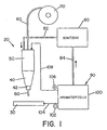
- Arc welding device 20 has a welding head 40 and a welding torch housing 50.
- Welding head 40 includes one Nozzle 42. Nozzle 42 facilitates alignment of the electrode on the workpiece.
- a welding electrode 60 is from a roll of welding wire 70 unrolled and into the welding torch housing 50 introduced. The welding electrode passes through the welding torch housing 50, leaves it through the welding head 40 and becomes a workpiece by means of the nozzle 42 30 led.
- a welding wire feed system not shown controls the feed rate of the electrode during the welding process.
- a shielding gas becomes the welding torch housing 50 supplied via a gas line 82 to a protective gas source 80 is connected.
- An inert gas control mechanism controls the flow rate during the welding process of the protective gas, i.e. of carbon dioxide, to the workpiece.
- the arc welding device is by means of a electrical energy source 90 supplied with energy.
- the electrical energy source 90 from a single fuel cell 100; the fuel cell
- 100 could also be used in combination with a variety of fuel cells and / or with other electrical energy sources used to the arc welding device to provide with energy.
- the fuel cell generates in Embodiment shown a direct current, as by means of of the positive pole and negative pole on the fuel cell is.
- the negative pole 102 is on the cable 104 Workpiece 30 connected.
- the positive pole 106 is via cable 108 connected to the welding torch housing 50.
- the fuel station 100 also for generating an alternating current could be designed.
- the fuel cell 100 is a reaction product that the inert gas source 80 is supplied via gas line 84.
- the production of the reaction product through the fuel cell continues to be explained below.
- the main components of the arc welding device i.e. Electrode, welding head, welding torch housing etc. are standard components of arc welding devices, so for a further description here is waived.
- the fuel cell 100 is designed such that it partially or completely takes over the energy supply for the arc welding device 20 and also supplies the shielding gas required during the arc welding of the workpiece 30.
- the fuel cell is preferably designed in such a way that it can be operated with organic supply means (supply), so that as a result the electrical supply energy for the arc welding device is generated and a reaction product is produced which is environmentally friendly.
- the organic supply agent is selected such that at least one of the reaction products can also be used as a protective gas source during the arc welding operation.
- a liquid-fuel cell converts the chemical energy of the fuel directly into electrical current without burning the fuel.
- the fuel cell offers numerous advantages over conventional energy sources, such as the fact that the fuel for the fuel cell is a substance which is widely and widely used, ie in particular methanol (a liquid which is also known as methyl alcohol), which is mixed with water. Methanol is cheap, easy to produce from coal or natural gas, and safe to store.
- Another advantage of the fuel cell is that it has a relatively low operating temperature (below the boiling point of water) and is relatively compact.
- the low operating temperature eliminates the need for special, high-melting materials, voluminous thermal insulation and reinforcing elements in order to minimize safety risks.
- the fuel cell does not produce any toxic by-products.
- the methanol is completely converted into carbon dioxide (CO 2 ) and water.
- the fuel cell is simple and relatively inexpensive to manufacture, since it consists almost exclusively of a membrane coated with platinum or another noble metal.
- the fuel cell itself has no moving parts. The precious metals are only required in small quantities and can be recovered and recycled at the end of the device life cycle. With no moving parts, the fuel cell is absolutely quiet during operation.
- the fuel cell converts more than 34% of the theoretical energy content of the fuel into usable energy. The efficiency is therefore twice as high as with existing petrol units.
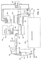
- the electrical energy source 90 is here as a stack 110 of individual cells 100 shown.
- Each of the individual cells, not shown has an anode, a cathode and a polymer membrane with one solid, proton-conducting and cation-exchanging polymer membrane as an electrolyte.
- the anode, cathode and the Solid polymer membrane electrolyte are preferably each as individual multi-layer structures hereinafter referred to as membrane electrolyte arrangement.
- a detailed description of each fuel cell 100 is disclosed in patent US 5,599,638, the content of which is mentioned expressly made to the disclosure content of this application becomes.
- a pump For pumping the organic fuel water solution a pump is in an anode chamber of the fuel cell 120 provided.
- the organic fuel water mixture will withdrawn through an exit opening 112 in the cell stack 110 and recirculated through a cycle tank 130.
- the Carbon dioxide formed in the anode chamber of the fuel cell degasses through opening 114.
- An oxidant supply 140 is provided to the cathode chamber of the fuel cell To feed oxygen and / or air.
- oxygen supply of oxidants 140 for dining with oxygen and / or air can for example, an oxygen bottle, an air fan and / or act as an air compressor.
- An air-water and / or oxygen-water mixture is from the cell stack 110 withdrawn via the outlet opening 114 and one Water recovery unit 150 supplied.
- the water recovery unit 150 separates air and / or oxygen from the Water. Part of the oxygen separated in unit 150 and / or the air becomes the oxidant supply 150 for re-entry into the stack cell or the cell stack 110 fed. The oxygen or the air from the oxidant supply 140 fresh air or fresh oxygen added. With that of unit 150 separated water becomes a fuel and water injection unit 160 fed, which also from a storage tank 170 receives an organic fuel, such as especially methanol. Injection unit 160 connects the water from the recovery unit 150 with the organic fuel from the tank 170, creating a fuel water solution consisting of in Water-soluble fuel that is generated.
- the fuel water solution created with the injection unit 160 is fed to a circulation tank 130. Furthermore, a Fuel water mixture containing carbon dioxide through opening 112 withdrawn from the cell stack 110, a heat exchanger 180 fed and then in the circulation tank 130 fed.
- the circulation tank 130 consequently receives both Fuel water solution from the injection unit 160 as well a fuel water solution containing carbon dioxide from the heat exchanger 180.
- the circulation tank 130 separates carbon dioxide from the fuel-water mixture and releases the carbon dioxide via lead 84 free.
- the fuel water solution thus obtained is pump 120 into the cell stack 110 fed.
- the circulation tank 130 could also be between the Cell stack 110 and the heat exchanger 180 are arranged, so that the carbon dioxide is separated before the heat exchanger becomes, which increases the efficiency of the heat exchanger is improved.
- a heating unit could be used to mix the methanol and water before feeding of the mixture in the fuel cell stack.
- a preheater not shown, could also be used to heat up the methanol-water mixture before the mixture flows to the cell stack.
- a Not shown methanol sensor can be used to the Sample methanol concentration to get the desired concentration to be able to keep up in the mixture.
- a not shown Oxygen sensor could be used to measure oxygen concentration measure and the required concentration in to be able to maintain the fuel cell.
- Circulation tank 130 is preferably a tower that has a large air space.
- the fuel-water mixture obtained from the injection unit 160 is supplied in an upper portion of the tower.
- the fuel-water mixture, which is provided with carbon dioxide, is fed into a lower section of the tower.
- the carbon dioxide gas separated from the fuel / water mixture can collect in the air space and ultimately be discharged via a valve 28 to a CO 2 processing unit 80 and / or be fed directly to the arc welding torch 20 via line 82.
- the CO 2 processing unit 80 may include a gas cleaner, a compressor, a dryer, and / or a condenser (not shown) to purify and / or compress the CO 2 gas from the cycle tank 130.
- the fuel-water mixture containing carbon dioxide can be passed through a tube bundle of microporous material which allows the gas to be released through the microporous tube walls while the liquid fuel flows along the tubes.
- a static recirculation system could be within an anode chamber of the cell stack 110 to separate carbon dioxide from the fuel-water mixture, so that an external circulation tank is not required would.
- the carbon dioxide bubbles would become strive for their own buoyancy energy, to ascend vertically within the anode chamber. Viscous interactions with the one surrounding the glass bubbles liquid fuel mixture then drag the liquid Fuel up toward exit port 114 to.
- the liquid Once the liquid is outside the anode chamber, it releases the gas, exchanges heat with the environment and cools, making their density higher than that of Liquid in the fuel cell.
- the bubble-free or denser Liquid is added to the bottom of the anode chamber Inlet opening fed. Instead of electrical energy at the Consuming the pump therefore uses the static recirculation system the heat generated in the fuel cell or generated gas.
- the aforementioned mode of operation forms the basis for the static recirculation system.
- the anode chamber of the fuel cell stack with the mixture of organic Fuel and water are filled and the cathode chambers are filled with Filled with air or oxygen. Circulated during operation the organic fuel past the anodes while oxygen or air flows to the cathodes. If an electric Circuit 200 between the anode and cathode of the cell stack an oxidation of the organic occurs Fuel at the anode and a reduction in oxygen the cathode. The different reactions at the anode and Cathode increase the voltage difference between the two Electrodes. The electrons generated at the anode by oxidation are passed through the welding circuit 200 and ultimately caught on the cathode. Generated at the anode Hydrogen ions or protons are directly across the membrane led to the cathode. A current flow is through a flow of Ions through the membrane and electrons through the welding circuit maintained.
- the membrane is made of a perfluorinated proton exchange material (PEM), such as a copolymer from tetrafluoroethylene and perfluorovinyl ether sulfonic acid.
- PEM perfluorinated proton exchange material
- Other membrane materials can also be used become.
- membranes could be made from modified perfluorinated sulfonic acid polymers, polyvalent hydrocarbon sulfonic acids or mixtures of these or more such proton exchange membranes (PEM) are used.
- PEM proton exchange membranes
- the anode is formed from platinum-ruthenium alloy particles, which can be fine metal dust, ie "self-supporting", or can be dispersed, ie "supported", on hard carbon surfaces.
- a carbon fiber underlayer can be used to make electrical contact with the particles of the electrocatalyst.
- both cantilevered and supported electrocatalysts could be chemically bonded to a fluoropolyamide binder and coated or pre-treated on carbon paper to produce the anode.
- platinum-ruthenium platinum-based alloys in which the second metal is either tin, iridium, osmium or remium could be used. In general, the choice of alloy depends on the fuel used in the fuel cell.
- Platinum-ruthenium is advantageous in the electro-oxidation of methanol.
- the loading of the alloy particles in the electrocatalyst layer is preferably in the range of approximately 0.05-4.0 mg / cm 2 . More efficient electrooxidation is achieved at higher loading levels than at lower loading levels.
- the anode structure for the liquid-fed fuel cell requires a structure that is similar to that of batteries.
- the anode structure is porous and able to wet the liquid fuel.
- the anode structure must have both electronic and ionic conductivity in order to efficiently transport the electrons to the anode current collector (carbon paper) and hydrogen-hydronium ions to the electrolyte membrane.
- the anode structure should help achieve the favorable gas release characteristics at the anode.
- the electrocatalyst layer and carbon fiber base of the anode are preferably impregnated with a hydrophilic, proton-conducting polymer additive.
- the addition in the anode is partially provided in order to enable efficient transport of the protons and hydronium ions generated in the oxidation reaction.
- the ionomeric additive also supports uniform wetting of the electrode pores with the liquid fuel / water mixture and ensures better use of the electrocatalyst.
- the kinetics of the electrooxidation of methanol is also improved with reduced anion absorption.
- the use of an ionomeric additive advantageously supports the gas release characteristics of the anode.
- the additive should be hydrophilic, proton-conducting and electrochemically stable and should not hinder the kinetics of the oxidation of the liquid fuel.
- the hydrophilic, proton-conducting additives that can be used can be a copolymer of fluorocarbon polymer or fluorocarbon sulfonic acid polymer, swellable clay (montmorillonite), zeolite, alkoxy cellulose, cyclodextrin and / or zirconium hydrogen phosphates.
- a loading of 0.05-0.5 mg / cm 2 is preferred.
- Electrode compositions with additives greater than 10% can lead to an increase in the internal resistance of the fuel cell and to poor bonding with the solid polymer membrane electrolyte. Compositions with less than 2% additives usually do not lead to improved electrode performance.
- the cathode is a gas diffusion electrode with platinum particles bonded to one side of the membrane.
- the cathode is preferably formed from free or supported platinum, which is applied to the side of the membrane opposite the anode.
- the cathode metal particles preferably adhere to a carbon base.
- the loading with electrocatalytic particles on the carbon base is preferably in the range of about 0.5-4.0 mg / cm 2 .
- the electrocatalyst alloy and carbon fiber backing preferably contain a fluoride polymer to provide the hydrophobicity required to create a three phase boundary and to efficiently drain the water generated in the oxygen reduction.
- a fuel-water mixture (which preferably contains neither acidic nor alkaline electrolytes) circulates past the anode at a concentration of about 0.5-3.0 mol / l.
- the flow rates are preferably around 10-500 mL / min.
- Air or oxygen preferably circulates behind the cathode at pressures in the range of 0-2.07 bar (0-30 PSIG). higher Pressures as ambient pressure can mass transport from Oxygen in particular contributes to the location of the chemical reaction improve high current densities. That with the electrochemical Water falling off at the cathode is reacted by means of oxygen flow transported away from the cathode through outlet 114.
- the thickness of the proton-conducting solid polymer membrane should be in the range of 0.05-0.5 mm in order to be size-stable. Membranes that are thinner than 0.05 mm can result in membrane electrode assemblies with poor mechanical properties, while membranes that are thicker than 0.5 mm can suffer extreme and deleterious size variations due to sources of the polymer through the liquid fuel water solution and also excessive Show resistance.
- the ion conductivity of the membranes should be greater than 1 ohm -1 cm -1 so that the fuel cell has a moderate internal resistance. As already mentioned, the membrane should have a low permeability to the liquid fuel.
- Membranes made of polyethylene and polypropylene sulfonic acid, polystyrene sulfonic acid and other polyvalent hydrocarbon sulfonic acids can be used depending on the temperature and duration of fuel cell operation.
- Composite membranes consisting of two or more types of proton-conducting, cation-exchanging polymers with different acid contents or different chemical compositions (such as modified acid or polymer basic structures), or different water contents or different types and dimensions of intermediate compounds (such as cross-connections between polyvalent cations, e.g. AL3 +, MG2 + etc.) can be used to achieve low fuel permeability.
- Such composite membranes can be made to achieve high ionic conductivity, low permeability to the liquid fuel and good electrochemical stability.
- Fig. 3 illustrates the fuel cell efficiency by the function curve of fuel cell power versus current density (in mA / cm 2 ).
- Fig. 3 shows the efficiency in a fuel cell which is fed with a single methanol solution at 90 ° C and an air mixture pressure of 1.37 bar (20 PSIG). The curve shows that approximately 0.48 volts can be maintained at approximately 400 mA / cm 2 by means of the fuel cell.
- the optimization of the fuel cell requires a comparison between current density and cell efficiency.
- 4 shows the power density as a function of the current density.
- the optimal operating point achieves a power density of approximately 230 mW / cm 2 .
- the optimal operating point occurs at current densities between 400 and 700 mA / cm 2 .
- the cell voltage within this range is between 0.48 and 0.31 volts. 5 shows the transient response or the transition function of the fuel cell.
- the settling time of the fuel cell is around 500-800 ms. This short settling time is suitable for use in arc welding torches, so that larger energy storage elements are not required.
- Fuel cells can be connected in series to provide adequate To get tension for welding. Because of the losses in the energy conversion circuit and in the cables and due to the equalization processes in the welding load is a Safety margin of a few volts provided. The safety margin is based on empirical values under typical Welding conditions and depends more or less on the current Circumstances. The cross-sectional area of the fuel cell is about the desired load current and the operating current density of the cell.
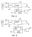
- Fig. 6 shows a welding circuit which has a power compensation converter (buck power converter).
- the table below shows the associated data for cell stack configurations when a compensation converter is used with common weld charges and operating conditions.
- the following operating conditions for the fuel cell were assumed: 220 mW / cm 2 and 500 mA / cm 2 (0.44 volts).
- the positive poles of the cell stack 110 are arranged on the side on which the oxidant is supplied and are connected to the input of the power converter circuit 200.
- the minus connection is on the side where fuel is supplied and is connected to a clamp on the workpiece 30.
- Welding circuit 200 is regulated to regulate the welding current in response to a feedback signal proportional to the welding voltage, welding current, or both. Reversing the welding electrode and workpiece connections would reverse the welding load current. For CO 2 welding processes, a structure with direct current and negative electrode is often desired.
- the cell stack 110 generates an excess amount of CO 2 for welding.
- the CO 2 can contain trace elements of water or methanol vapor, which must be removed before the gas is fed into the arc welding torch.
- a gas dryer can be used to ensure that the gas is free of vapor contaminants.
- the fuel cell is operated at pressures which exceed ambient pressure, so that compression of the CO 2 is generally not necessary. However, if the operating pressure of the fuel cell is too low, the CO 2 gas can be compressed before it is fed to the welding arc.
- the flow rate of the shielding gas must be regulated to an appropriate level to avoid excessive arc disturbances. Since the fuel cell produces more CO 2 than is required to protect the arc, a flow regulator can be provided so that only a suitable amount of shielding gas flows. The rest of the CO 2 is suctioned off or used for other purposes.
- Fig. 6 shows the electrical connection in one configuration with direct current and positive electrode.
- a power converter circuit is used to output the fuel cell to match the welding load.
- Fig. 6 shows for a compensation converter (chopper).
- the Welding circuit 200 has a transistor 210 that is controlled by means of a welding control system 220.
- the Sweat control system controls the waveform of the Welding device supplied current.
- the welding control system can rely on feedback monitoring during the Support operation of the arc welding torch.
- the welding circuit further includes a diode 230 to detect an appropriate one Maintain current flow through the electrode.
- the welding circuit has an inductor around which smoothing welding current waveform flowing through the electrode. The cell stack performance should always meet the balancing load requirements exceed the compensation converter works effectively.
- FIG. 7 shows the topology of an additional voltage compensation converter.
- the additional voltage compensation circuit in the welding circuit 200 is constructed in such a way that the voltage at the electrode is increased without the number of fuel cells in the cell stack 110 having to be increased.
- Welding circuit 200 includes a welding control system 220 that is similar to the control system of FIG. 6.
- the welding circuit further includes an inductor 250, a capacitor 260 and a transistor 270 which is controlled by the welding control system 220 to boost the voltage through the welding circuit.
- the function of diodes 280, 290, transistor 300 and inductor 310 which operate similarly to the chopper or compensation circuit in Fig.
- Cell stack configuration - compensation power converter stage Number of cells in the stack 35 45 60 75 100 125 Cell stack voltage 15.4 19.8 26.4 33.0 44.0 55.0 Welding current (A) Welding voltage (V) Load power (KW) Cell cross-sectional area (cm 2 ) Cell cross-sectional area (cm 2 ) Cell cross-sectional area (cm 2 ) Cell cross-sectional area (cm 2 ) Cell cross-sectional area (cm 2 ) Cell cross-sectional area (cm 2 ) 0 15.0 0.0 0 0 0 0 0 100 20.0 2.0 248 193 145 116 87 70 150 22.5 3.4 419 326 245 196 147 117 200 25.0 5.0 621 483 362 290 217 174 300
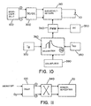
- FIGS. 8 and 9 schematically show control circuits for TIG welding torch.
- a non-melting one Electrode such as a tungsten electrode is kept at a sufficient distance from the workpiece in order to To get arcing when due to an applied across the gap Voltage a current flows.
- Aluminum is very fast oxidized, it is necessary to remove the aluminum oxides from the Remove welding surface while the arc heat Melted cored wire and deposited on the aluminum workpiece.
- the metal is created by applying an AC power supply to direct an alternating current through the Gap or space between the electrode and the workpiece is cleaned. During a positive cycle, the electrode is relieved of the workpiece positive; consequently, from the workpiece Electrons emitted.
- This process removes and removes aluminum oxides from the surface in preparation for the immediate subsequent negative cycle, with the tungsten or other non-melting electrons negative relative to the workpiece are. Electrons are in from the tungsten electrode Direction to the workpiece is emitted to be comparatively effective to be heated in the arc area. By using AC over the arc become main cleaning cycles and generated heating cycles, making it a fairly efficient one TIG welding process for aluminum is created.
- the welder When using DC power sources in TIG welding the welder must select the polarity to be used. If unalloyed or stainless steel is welded should not be cleaned, so that DC TIG welding can be used with a negative electrode. This polarity does not ensure that an oxide layer is removed Arc cleaning action; if this system for aluminum welding cleaning must be used as preliminary welding work and removal of the oxide layer on the welding surface be performed. However, this is only useful if heavy aluminum plates are TIG-welded and the additional Pre-cleaning work due to the increased welding speed when using the electrode with negative polarity be balanced. Because of this, the Welders often use TIG welding with DC and positive Electrode, where then current from the electrode to the workpiece flows. This results in combination with the arc welding process a cleaning effect.
- the modified direct current is then fed to a switching network 310.
- the Switch network 310 converts direct current to alternating current for use in a TIG welding device.
- On Wave profile 320 controls switching in the switching network, the duration of the positive and negative pulses during to control the welding cycle.
- a pulse width adjuster 330 provides the Pulse duration of positive and / or negative pulse.
- the welding circuit is capable of a normal DC fuel cell for use with a TIG welding device to convert to an AC power source.
- the Welding can also be done with melting welding electrodes be performed.
- the melting electrode is melted and on the workpiece by means of spherical transmission, Short circuit transmission, pulse current transmission etc. filed. It can be advantageous for these metal transmission systems switch from a positive current to a negative current, to increase the melting rate of the electrode or others To gain benefits.
- the welding circuit can be used to generate a short-term reversal of the current polarity be used in welding as in TIG welding place.
- the welding circuit has the advantages of a normal AC TIG welding device with the additional performance, the extent of heating and cleaning the To be able to adjust the workpiece for a short period.
- the Welding circuit can change the ratio of plus to negative power regulate to the extent of during the positive current flow controlled cleaning.
- the welding circuit can also be used to reduce arcing be used. Welding with melting Usually brings electrodes at high DC levels Arc warping with it due to magnetic field interactions caused by the arc plasma.
- the welding circuit can reduce the effect of arcing by briefly reversing the arc current to reduce.
- the 10 is a fuel cell 100 as an energy supply shown for an STT welding torch type.
- the direct current of the Fuel cell provides power to the DC / DC circuit 300.
- the DC / DC circuit can be constructed as described in FIGS. 8 and 9 his.
- the current from the DC / DC circuit goes to the switching network 310.
- the switching network forms the desired one Waveform for the current on the workpiece 30.
- the switching network is generated by a pulse width modulator (PWM) 340 controlled, which is regulated by means of an oscillator (OSC) 350 becomes.
- PWM pulse width modulator
- OSC oscillator
- the desired waveform for the current on workpiece 30 is set using the STT waveform profile 360.
- a background current setting device 370 and a maximum current setting device 380 are used to create the waveform profile to modify.
- a decay current at the end of the waveform is controlled by a trailing edge adjuster 390.
- the welding circuit can change the polarity of the waveform during a single welding cycle or during different Welding cycles by using the polarity reversal circuit control from Fig. 11.
- the electrode changes between a short-circuit condition, when the electrode touches the workpiece, and an arc condition where the electrode is off the workpiece is spaced back and forth.
- an electrical arc between the workpiece and the electrode for melting and maintaining the melted Electrode end generated while this for one subsequent short circuit condition is supplied to the workpiece.
- the welding cycle changes between short circuit and plasma state.
- the pulse width modulator operates at high Frequencies.
- the operating frequency of the pulse width modulator is around 10-30 kHz, the width of the following Current pulse determined by the voltage at the waveform controller becomes. Since the maximum rate of the welding cycle is generally in The range of 100-400 cycles per second will be numerous updated pulses generated during each welding cycle.
- the welding cycle directs electricity to the work area depending from operating the pulse width modulator controller until the Functions dr / dt (where r is the electron resistance), di / dt or dv / dt an impending burnout during the pinch cycle Show. As soon as this is detected, the means the welding circuit between the electrode and the Workpiece immediately caused current flow to a lower level lowered.
- the background current circuit continues to apply a current of 5-7 A regardless of the operating condition of the welding circuit on.
- the background current ensures that a Current of at least 5-7 A at any time during the welding cycle flows between the electrode and the workpiece, causing a Extinguishing the arc between the electrode and the Workpiece prevented during every phase of the welding cycle becomes.
- the electrode 60 is preferably a melting one Soul electrode, which has an outer metal shell and a Has electrode core. It is understood that alternatively the electrode could be coated or a solid wire.
- the metal electrode shell is preferably made of carbon steel, stainless steel or other metal or metal alloy educated.
- the composition of the metal shell is preferably chosen to be similar to the metal composition of the workpiece.
- the electrode core points preferably flux additives and / or alloys and metals on.
- the flux can contain ingredients to create a Have slag over the weld pool to close the weld pool protect until it hardens to the weld pool until hardening hold in place and / or around the weld metal during shield the formation of the weld pool.
- the flux may also have components that form protective gas to the To protect the root bed from adverse environmental effects.
- the alloy additives are preferably included in the electrode core.
- the alloy additives are preferably such chosen that the alloy additives in accordance with the composition form a weld pool for the metal electrode sleeve, which has a composition similar to the metal composition of the workpiece.
- Fig. 10 shows a desired current profile to minimize splashing during welding.
- This welding profile is in a pinch section, a plasma amplification section, a plasma section and a background section divided, while the arc is maintained.
- the Plasma amplification section which the critical area at Operation of the control system against splashes is here the constant current section before the decay section; the However, the decay section can also be the end of the plasma amplification section or assigned to the beginning of the plasma section become. Following the decay section, the Current control circuitry to the background current level that the Plasma or the arc maintains.
- the current control circuit holds a preselected one according to the invention Background current level upright, which prevents that the current level at the arc will eventually fall below the preselected one Low current level could drop at which the arc would go out.
- the current control circuit is designed so that it does everything Melting of the electrode during the plasma amplification and plasma portion of the welding cycle. On further melting of the electrode takes place at background current level not instead, because of the melting of the electrode necessary resistance current with the arc only maintaining by means of background current Current level is not available. The background stream therefore only serves to maintain the arc and Molten metal drop in the molten state.
- the amount on molten metal at the electrode end, caused by the plasma amplification and the plasma is formed is chosen such that they have a predetermined volume of molten metal melts at the end of the electrode, and the plasma section of the Current is reduced to background current as soon as the predetermined one Volume is obtained.
- the duration of the plasma amplification and plasma section can also be selected.
- the jet forces collide in the plasma section of the stream of the high current the molten metal from the weld pool until the desired amount of molten metal from Electrode end was melted.
- the electricity is reduced molten metal can form into a ball and the weld pool can stabilize, causing a even contact between the essentially spherical Ball and the suppressed sweat metal bath arises.
- the most Electrode end becomes the desired amount of molten metal by straightening a preselected amount of energy or wattage during the plasma section of the welding cycle Electrode controlled into it.
- the Melting ball shielded from the atmosphere by means of protective gas. The inert gas flow continues until the melted ball into the melted metal was transferred.
- the current control circuit monitors the necking of the molten metal ball such that the current flow during the pinch curve increases more when the Constriction extremely fast in diameter due to electrical Holes reduced until an impending breakdown is detected becomes. As soon as an impending breakdown occurs, the current is reduced to the background current level, until the molten metal at the end of the electrode enters the Melt pool crosses.
- the current can be positive at any time, negative at all times or a combination of positive and negative Be pulsing.
- the number of current cycles of positive polarity and negative Controlled polarity to the desired warming in the to get molten metal puddle of the welding process. If the puddle is too cold, the number of cycles becomes 320 with negative polarity relative to the number of cycles positive Electricity increased.
- the desired ratio is indicated by receive a suitable selection circuit in the welding controller.
- An alternative control concept can also be used, where every welding cycle starts with a standard cycle is negative polarity, which subsequently becomes a predetermined one Time in the cycle into a cycle with positive polarity is switched.
- the Polarity of the rapidly generated current pulse are switched, after the plasma enhancement section has ended.
- the final flank section becomes a negative section and a positive section with sudden polarity reversal divided.
- the current cycle then has one positive polarity until the end of the cycle. In this way the welding puddle heat by selecting the time delay the polarity reversal during the welding cycle.
- To at one STT welding device to control the heat during the welding process between a positive polarity and a negative one Switching the polarity of the current pulses back and forth could be more Modifications are made.
Landscapes
- Engineering & Computer Science (AREA)
- Physics & Mathematics (AREA)
- Plasma & Fusion (AREA)
- Mechanical Engineering (AREA)
- Chemical & Material Sciences (AREA)
- General Chemical & Material Sciences (AREA)
- Sustainable Development (AREA)
- Sustainable Energy (AREA)
- Life Sciences & Earth Sciences (AREA)
- Chemical Kinetics & Catalysis (AREA)
- Electrochemistry (AREA)
- Manufacturing & Machinery (AREA)
- Fuel Cell (AREA)
- Arc Welding Control (AREA)
- Arc Welding In General (AREA)
- Inert Electrodes (AREA)
- Electrolytic Production Of Non-Metals, Compounds, Apparatuses Therefor (AREA)
- Apparatus Associated With Microorganisms And Enzymes (AREA)
- Butt Welding And Welding Of Specific Article (AREA)
Abstract
Description
| Zellenstapelkonfiguration--Leistungs-Kompensationskonverterstufe | ||||||
| Schweißstrom | Schweiß spannung | Lastleistung | Spannungsreserve | Gesamtspännung | Zellenanzahl im Zellenstapel | Zellenquerschnittsfläche (cm2) |
| 0 | 15.0 | 0.0 | 13 | 28 | 63 | 0 |
| 100 | 20.0 | 2.0 | 14 | 34 | 77 | 113 |
| 150 | 22.5 | 3.4 | 14.5 | 37 | 84 | 175 |
| 300 | 30.0 | 9.0 | 16 | 46 | 104 | 376 |
| 400 | 35.0 | 14.0 | 17 | 52 | 118 | 516 |
| 500 | 40.0 | 20.0 | 18 | 58 | 131 | 664 |
| Zellenstapelkonfiguration - Kompensationsleistungskonverterstufe | ||||||||
| Zellenanzahl im Stack = | 35 | 45 | 60 | 75 | 100 | 125 | ||
| Zellenstapelspannung = | 15,4 | 19,8 | 26,4 | 33,0 | 44,0 | 55,0 | ||
| Schweißstrom (A) | Schweißspannung (V) | Lastleistung (KW) | Zellenquerschnitts fläche (cm2) | Zellenquerschnitts fläche (cm2) | Zellenquerschnitts fläche (cm2) | Zellenquerschnitts fläche (cm2) | Zellenquerschnitts fläche (cm2) | Zellenquerschnittfläche (cm2) |
| 0 | 15.0 | 0.0 | 0 | 0 | 0 | 0 | 0 | 0 |
| 100 | 20.0 | 2.0 | 248 | 193 | 145 | 116 | 87 | 70 |
| 150 | 22.5 | 3.4 | 419 | 326 | 245 | 196 | 147 | 117 |
| 200 | 25.0 | 5.0 | 621 | 483 | 362 | 290 | 217 | 174 |
| 300 | 30.0 | 9.0 | 1118 | 870 | 652 | 522 | 391 | 313 |
| 400 | 35.0 | 14.0 | 1739 | 1353 | 1014 | 812 | 609 | 487 |
| 500 | 40.0 | 20.0 | 2484 | 1932 | 1449 | 1159 | 870 | 696 |
Claims (53)
- Lichtbogenschweißvorrichtung zum Ausbilden einer Schweißraupe auf einem Werkstück (30), aufweisend eine elektrische Energiequelle (90), einen Schweißschaltkreis (200), und eine Schweißelektrode, wobei die elektrische Energiequelle (90) ausreichend Spannung und Strom für den Schweißschaltkreis (200) erzeugt, um ein Ausbilden eines elektrischen Lichtbogens zwischen Elektrode (60) und Werkstück (30) zu erzwingen, und wobei mit dem Schweißschaltkreis zumindest ein Schweißparameter zwischen der Elektrode und dem Werkstück zumindest teilweise gesteuert ist, welcher Schweißparameter aus Spannung, Strom, Energie, Leistung, Polarität oder einer Kombinationen hieraus besteht, dadurch gekennzeichnet, daß die Energiequelle (90) einen Zellenstapel (110) oder stack aus mehreren Brennstoffzellen (100) umfaßt, der eine Stapelzellenspannung von zumindest etwa 15,4 V hat und ausreichend Energie zum Erzeugen eines Schweißstroms von zumindest etwa 100 A und einer Schweißspannung von zumindest etwa 20 V liefert, wobei zumindest eine der Brennstoffzellen (100) eine indirekte Brennstoffzelle, eine direkte Brennstoffzelle oder eine Kombination aus indirekter und direkter Brennstoffzelle ist.
- Vorrichtung nach Anspruch 1, dadurch gekennzeichnet, daß der Schweißschaltkreis (200) eine Kompensationsschaltung zum Steigern der Spannung der elektrischen Energiequelle aufweist.
- Vorrichtung nach Anspruch 2, dadurch gekennzeichnet, daß der Zellenstapel aus mehreren Brennstoffzellen eine Lastleistung von zumindest etwa 2 KW erzeugt und mehrere der Brennstoffzellen ein organisches Versorgungs- oder Brennstoffmittel umfassen, wobei das organische Versorgungs- oder Brennstoffmittel aus Methanol, Formaldehyd, Formylsäure, Dimetoxydmethan, Trimetoxydmethan, Trioxan oder aus Kombinationen hieraus besteht.
- Vorrichtung nach einem der Ansprüche 1 bis 3, dadurch gekennzeichnet, daß der Schweißschaltkreis eine Zusatzspannungs-Kompensationsschaltung zum Steigern der Spannung der elektrischen Energieversorgungsquelle aufweist.
- Vorrichtung nach einem der Ansprüche 2 bis 4, dadurch gekennzeichnet, daß die elektrische Energiequelle eine Spannung erzeugt, die die Anforderungen an den Einschwingladevorgang für die Kompensationsschaltung übersteigt.
- Vorrichtung nach einem der Ansprüche 1 bis 5, dadurch gekennzeichnet, daß der Schweißschaltkreis (200) einen Schweißstromschaltkreis umfaßt, der die Elektrode (60) mit Strom versorgt, wobei der Schweißstromschaltkreis die Wellenform des Stroms zur Elektrode derart regelt, daß eine zum Ausbilden der Schweißraupe auf dem Werkstück ausreichende Strommenge geliefert wird.
- Vorrichtung nach einem der Ansprüche 1 bis 6, dadurch gekennzeichnet, daß der Schweißschaltkreis (200) einen Schweißstromschaltkreis umfaßt, der die Elektrode (60) mit Strom versorgt, wobei der Schweißstromschaltkreis eine erste Schaltung zum Erzeugen eines Übergangsstroms und eine zweite Schaltung zum Erzeugen eines Schmelzstroms aufweist, wobei die zweite Schaltung eine ausreichende Menge von Strom an die Elektrode liefert, um die Schweißraupe auf dem Werkstück (30) auszubilden.
- Vorrichtung nach Anspruch 7, dadurch gekennzeichnet, daß die zweite Schaltung die Strommenge an der Elektrode reduziert, bevor das aufgeschmolzene Material an der Elektrode (60) einen Kurzschlußzustand mit dem Werkstück (30) bildet.
- Vorrichtung nach Anspruch 7 oder 8, dadurch gekennzeichnet, daß die zweite Schaltung ein Stromverzögerungsprofil erzeugt, wenn der Strom reduziert ist.
- Vorrichtung nach einem der Ansprüche 7 bis 9, dadurch gekennzeichnet, daß die erste Schaltung einen Hochstrompuls am Ende eines Kurzschlußzustands zwischen der Elektrode (60) und dem Werkstück (30) liefert und daß der Puls bis kurz vor einer vorberechneten Beendigung des Kurzschlußzustandes angelegt bleibt.
- Vorrichtung nach einem der Ansprüche 7 bis 10, dadurch gekennzeichnet, daß die erste Schaltung und/oder die zweite Schaltung die zum Schweißdraht gelieferte Strommenge reduziert, bevor das geschmolzene Metall an der Elektrode mit dem Werkstück einen Kurzschlußzustand bildet.
- Vorrichtung nach einem der Ansprüche 1 bis 10, dadurch gekennzeichnet, daß der Schweißschaltkreis oder der zweite Schaltkreis eine vorgewählte Energiemenge zum Schweißdraht (60) lenkt, um ein vergleichsweise konstantes Volumen der Elektrode während jedem Schweißzyklus abzuschmelzen.
- Verfahren zum Ausbilden einer Schweißraupe auf einem Werkstück beim elektrischen Lichtbogenschweißen, mit den Schritten:a) Bereitstellen einer Elektrode;b) Bereitstellen einer Energiequelle (90), die einen Strom erzeugt; dadurch gekennzeichnet, daßc) die Energiequelle (90) mehrere Brennstoffzellen umfaßt und der Zellenstapel (110) oder stack aus mehreren Brennstoffzellen eine Stapelzellenspannung von zumindest etwa 15,4 V hat und ausreichend Energie zum Erzeugen eines Schweißstroms von zumindest etwa 100 A und einer Schweißspannung von zumindest etwa 20 V liefert, wobei zumindest eine der Brennstoffzellen (100) eine indirekte Brennstoffzelle, eine direkte Brennstoffzelle oder eine Kombination aus indirekter und direkter Brennstoffzelle ist; undd) mit dem bereitgestellten Strom ein Lichtbogen zwischen Elektrode und Werkstück gebildet wird.
- Verfahren nach Anspruch 13, dadurch gekennzeichnet, daß ein Schweißschaltkreis vorgesehen ist oder wird, der eine Spannungsverstärkungsschaltung zum Steigern der Spannung der elektrischen Energiequelle aufweist.
- Verfahren nach Anspruch 14, dadurch gekennzeichnet, daß die Spannungsverstärkungsschaltung eine Kompensationsschaltung umfaßt.
- Verfahren nach Anspruch 14 oder 15, dadurch gekennzeichnet, daß die Spannungsverstärkungsschaltung eine Zusatzspannungs-Kompensationsschaltung umfaßt.
- Verfahren nach einem der Ansprüche 14 bis 16, dadurch gekennzeichnet, daß die elektrische Energiequelle eine Spannung erzeugt, die die Anforderungen an den Einschwingladevorgang für die Spannungsverstärkungsschaltung übersteigt.
- Verfahren nach einem der Ansprüche 13 bis 17, wobei die Energiequelle eine elektrische Energiequelle ist, dadurch gekennzeichnet, daß der Zellestapel von mehreren Brennstoffzellen eine Lastleistung von zumindest etwa 2 KW erzeugt und mehrere der Brennstoffzellen ein organisches Versorgungs- oder Brennstoffmittel umfassen, das aus Methanol, Formaldehyd, Formylsäure, Dimetoxydmethan, Trimetoxydmethan, Trioxan oder aus Kombinationen hieraus besteht, wobei ein Schweißschaltkreis vorgesehen ist, der eine Spannungsverstärkungsschaltung zum Steigern der Spannung der elektrischen Energiequelle aufweist, wobei die Energiequelle eine Spannung erzeugt, die die Anforderungen an den Einschwingladevorgang für die Spannungsverstärkungsschaltung übersteigt, und wobei der Strom zum Erzeugen eines Lichtbogens zwischen der Elektrode und dem Werkstück dem Schweißschaltkreis zugeführt wird.
- Verfahren nach Anspruch 18, dadurch gekennzeichnet, daß mit dem Schweißschaltkreis eine elektrische Wellenform an der Elektrode ausgebildet wird, die einen Kurzschlußübertragungsabschnitt und einen gesteuerten Abschmelzabschnitt aufweist.
- Verfahren nach Anspruch 19, dadurch gekennzeichnet, daß der gesteuerte Abschmelzabschnitt gebildet wird durch Anlegen einer vorbestimmten Energiemenge an der Elektrode oder Anlegen einer vorbestimmten Leistungsmenge an der Elektrode.
- Verfahren nach einem der Ansprüche 18 bis 20, dadurch gekennzeichnet, daß der Schweißschaltkreis einen Hintergrundstrom erzeugt, wobei der Hintergrundstrom eine Komponente mit hoher Induktanz und ein Niedrigniveau hat, das gerade oberhalb desjenigen Niveaus liegt, um einen Lichtbogen zwischen Elektrode und Werkstück während des gesamten Schweißzyklus zu erhalten.
- Verfahren nach einem der Ansprüche 18 bis 21, dadurch gekennzeichnet, daß der Schweißschaltkreis die Polarität der an die Elektrode gelieferten elektrischen Welle steuert.
- Verfahren nach einem der Ansprüche 18 bis 22, dadurch gekennzeichnet, daß die elektrische Welle eine Serie von Strompulsen kurzer Breite aufweist, die jeder eine vorgegebene elektrische Polarität haben.
- Verfahren nach Anspruch 22 oder 23, dadurch gekennzeichnet, daß die Polarität der elektrischen Welle während des Schweißzyklus zwischen einer Pluspolarität und einer Minuspolarität hin- und hergeschaltet wird.
- Verfahren nach einem der Ansprüche 22 bis 24, dadurch gekennzeichnet, daß die Polarität der elektrischen Welle als Funktion der an Elektrode und Werkstück angelegten, aufsummierten Energiemenge in der einen Polarität bzw. der an Werkstück und Elektrode in der anderen Polarität angelegten, aufsummierten Energiemenge gewechselt wird.
- Verfahren nach einem der Ansprüche 14 bis 17, dadurch gekennzeichnet, daß der Schweißschaltkreis (200) einen Schweißstromschaltkreis umfaßt, der die Elektrode (60) mit Strom versorgt, wobei der Schweißstromschaltkreis die Wellenform des Stroms zur Elektrode derart regelt, daß eine zum Ausbilden der Schweißraupe auf dem Werkstück ausreichende Strommenge geliefert wird.
- Verfahren nach Anspruch 26, dadurch gekennzeichnet, daß der Schweißschaltkreis eine vorgewählte Energiemenge zum Schweißdraht (60) lenkt, um ein vergleichsweise konstantes Volumen der Elektrode während jedem Schweißzyklus abzuschmelzen.
- Verfahren nach Anspruch 26 oder 27, dadurch gekennzeichnet, daß der Schweißschaltkreis (200) einen Schweißstromschaltkreis umfaßt, der die Elektrode (60) mit Strom versorgt, wobei der Schweißstromschaltkreis eine erste Schaltung zum Erzeugen eines Übergangsstroms und eine zweite Schaltung zum Erzeugen eines Schmelzstroms aufweist, wobei die zweite Schaltung eine ausreichende Menge von Strom an die Elektrode liefert, um die Schweißraupe auf dem Werkstück (30) auszubilden.
- Verfahren nach Anspruch 28, dadurch gekennzeichnet, daß der zweite Schaltkreis ein Stromverzögerungsprofil erzeugt, wenn der Strom reduziert ist.
- Verfahren nach Anspruch 28 oder 29, dadurch gekennzeichnet, daß die erste Schaltung einen Hochstrompuls am Ende eines Kurzschlußzustands zwischen der Elektrode (60) und dem Werkstück (30) liefert und daß der Puls bis kurz vor einer vorberechneten Beendigung des Kurzschlußzustandes angelegt bleibt.
- Verfahren nach einem der Ansprüche 28 bis 30, dadurch gekennzeichnet, daß die erste Schaltung und/oder die zweite Schaltung die an den Schweißdraht gelieferte Strommenge reduziert, bevor das geschmolzene Metall an der Elektrode mit dem Werkstück einen Kurzschlußzustand bildet.
- Verfahren nach einem der Ansprüche 13 bis 31, dadurch gekennzeichnet, daß die Polarität des an die Elektrode gelieferten Stroms gesteuert oder geregelt wird.
- Verfahren nach einem der Ansprüche 13 bis 32, dadurch gekennzeichnet, daß der Strom eine Serie von Strompulsen kurzer Breite aufweist, die jeder eine vorgegebene elektrische Polarität haben.
- Verfahren nach ein Anspruch 32 oder 33, dadurch gekennzeichnet, daß die Polarität des Stroms als Funktion der an Elektrode und Werkstück angelegten, aufsummierten Energiemenge in der einen Polarität bzw. der an Werkstück und Elektrode in der anderen Polarität angelegten, aufsummierten Energiemenge gewechselt wird.
- Vorrichtung oder Verfahren nach einem der Ansprüche 1 bis 34, dadurch gekennzeichnet, daß der Zellenstapel von Brennstoffzellen oder zumindest eine der Brennstoffzellen eine optimale Einschwingzeit zwischen etwa 500 und 800 ms und einen optimalen Betriebspunkt bei einer Stromdichte zwischen etwa 400 und 700 mA/cm2 hat.
- Vorrichtung oder Verfahren nach einem der Ansprüche 1 bis 35, dadurch gekennzeichnet, daß der Schweißschaltkreis eine Hintergrundstromschaltung aufweist, die die Elektrode mit einem Hintergrundstrom versorgt und/oder daß der Schweißschaltkreis zumindest teilweise die Wellenform oder das Signal des an die Elektrode gelieferten Stroms steuert.
- Vorrichtung oder Verfahren nach einem der Ansprüche 1 bis 36, dadurch gekennzeichnet, daß der Schweißschaltkreis (200) einen Strompolaritätsregler zum Regeln der Polarität zumindest eines Abschnitts des die Elektrode durchfließenden Stroms aufweist.
- Vorrichtung oder Verfahren nach Anspruch 37, dadurch gekennzeichnet, daß der Schweißschaltkreis (200) eine Serie von Strompulsen geringer Pulsbreite erzeugt, die einen Schweißzyklus mit einem Kurzschlußübertragungsabschnitt und einem Plasmalichtbogenschmelzabschnitt ausbilden, wobei die Strompulse in dem Zyklus jeweils eine vorgegebene elektrische Polarität haben, die mittels des Polaritätsreglers zwischen einer ersten Polarität, die positiv ist, und einer zweiten Polarität, die negativ ist, wählbar ist.
- Vorrichtung oder Verfahren nach Anspruch 37 oder 38, dadurch gekennzeichnet, daß der Polaritätsregler einen Decoder umfaßt, der in einem ersten Zustand zwischen einer ersten oder zweiten Polarität für eine Anzahl von aufeinanderfolgenden Schweißzyklen und in einem zweiten Zustand die jeweils andere Polarität für eine zweite Anzahl von aufeinanderfolgenden Schweißzyklen wählen kann, und daß ein Mechanismus zum Umschalten zwischen dem ersten und zweiten Zustand im Schweißbetrieb vorgesehen ist.
- Vorrichtung oder Verfahren nach einem der Ansprüche 1 bis 39, dadurch gekennzeichnet, daß der Schweißschaltkreis einen zentral angezapften Induktor mit einem ersten Abschnitt zum Erzeugen einer ersten Polarität und einem zweiten Abschnitt zum Erzeugen einer zweiten Polarität, einen ersten Schalter zum Verbinden des ersten Induktorabschnitts zwischen der Elektrode und dem Werkstück, einen zweiten Schalter zum Verbinden des zweiten Abschnitts des Induktors zwischen Elektrode und Werkstück, und ein Einstellmittel zum Schließen entweder des ersten Schalters oder des zweiten Schalters während eines vorgegebenen Schweißzyklus, aufweist.
- Vorrichtung oder Verfahren nach einem der Ansprüche 1 bis 40, dadurch gekennzeichnet, daß die Brennstoffzelle (100) oder zumindest eine der Brennstoffzellen (100) eine Anode, eine Kathode und zumindest eine zwischen der Anode und der Kathode angeordnete, protonenleitende Feststoff-Polymermembran aufweist.
- Vorrichtung oder Verfahren nach Anspruch 41, dadurch gekennzeichnet, daß die Anode ein Metall umfaßt, das aus der Gruppe von Platin-Rutheniumlegierung, Platin-Zinn, Platin-Iridium, Platin-Osmium, Platin-Renium oder Mischungen daraus ausgewählt ist.
- Vorrichtung oder Verfahren nach Anspruch 41 oder 42, dadurch gekennzeichnet, daß die protonleitende Polymermembran ein Material aufweist, das aus einer Gruppe ausgewählt ist, die aus einem Copolymer von Tetrafluorethylen und perfluorinierter Sulfonsäure, perfluoriniertem Sulfonsäurepolymer, Polykohlenwasserstoff-Sulfonsäure oder eine Mischung daraus besteht.
- Vorrichtung oder Verfahren nach einem der Ansprüche 41 bis 43, dadurch gekennzeichnet, daß die protonleitende Polymermembran einen Katalysator umfaßt, der ein Material aufweist, das aus der Gruppe ausgewählt ist, die aus Ir, Mo, Nb, Nu, Os, Pd, Pt, Re, Ru, RuO2, Sn, SnO2, Ti, W, WO3, Zr oder Kombinationen hieraus besteht.
- Vorrichtung oder Verfahren nach einem der Ansprüche 41 bis 44, gekennzeichnet durch wenigstens zwei protonleitende, feste Polymermembranen, wobei die eine der Polymermembranen eine andere Zusammensetzung als die andere Polymermembran hat.
- Vorrichtung oder Verfahren nach einem der Ansprüche 1 bis 45, dadurch gekennzeichnet, daß zumindest eine der Brennstoffzellen mit organischem Brennstoff gespeist ist.
- Vorrichtung oder Verfahren nach einem der Ansprüche 1 bis 46, dadurch gekennzeichnet, daß der organische Brennstoff aus einer Gruppe ausgewählt ist, die Methanol, Formaldehyd, Formylsäure, Dimetoxymethan, Trimytoxymethan, Trioxan oder Kombinationen enthält.
- Vorrichtung oder Verfahren nach Anspruch 47, dadurch gekennzeichnet, daß zumindest eine der Brennstoffzellen flüssiggespeist ist.
- Vorrichtung oder Verfahren nach Anspruch 46, 47 oder 48, dadurch gekennzeichnet, daß zumindest eine der Brennstoffzellen ein Gasreaktionsprodukt bildet, das zumindest teilweise als Schutzgas verwendbar ist.
- Vorrichtung oder Verfahren nach Anspruch 49, dadurch gekennzeichnet, daß das Gasreaktionsprodukt eine Gas umfaßt, das aus Kohlenmonoxyd, Kohlendioxyd oder Mischungen hiermit besteht.
- Vorrichtung oder Verfahren nach einem der Ansprüche 1 bis 50, dadurch gekennzeichnet, daß die Elektrode eine abschmelzende Elektrode, eine Metallelektrode oder eine abschmelzende Elektrode mit Metallkern und Flußmittel ist.
- Vorrichtung oder Verfahren nach Anspruch 51, dadurch gekennzeichnet, daß die abschmelzende Elektrode mit Metallkern und Flußmittel Legierungsbestandteile im Kern zum Ausbilden einer Schweißraupe aufweist, wobei die Legierungsbestandteile im wesentlichen eine ähnliche Zusammensetzung aufweisen wie die Zusammensetzung des Werkstücks.
- Verwendung einer Brennstoffzelle (100) zur Strom- und Spannungsversorgung in einer Lichtbogenschweißvorrichtung oder in einem Lichtbogenschweißverfahren nach einem der Ansprüche 1 bis 52.
Applications Claiming Priority (3)
| Application Number | Priority Date | Filing Date | Title |
|---|---|---|---|
| US09/457,156 US6331694B1 (en) | 1999-12-08 | 1999-12-08 | Fuel cell operated welder |
| US457156 | 1999-12-08 | ||
| EP00126415A EP1106295B1 (de) | 1999-12-08 | 2000-12-05 | Lichtbogenschweissvorrichtung und -verfahren mit Brennstoffzelle |
Related Parent Applications (1)
| Application Number | Title | Priority Date | Filing Date |
|---|---|---|---|
| EP00126415A Division EP1106295B1 (de) | 1999-12-08 | 2000-12-05 | Lichtbogenschweissvorrichtung und -verfahren mit Brennstoffzelle |
Publications (3)
| Publication Number | Publication Date |
|---|---|
| EP1378311A2 true EP1378311A2 (de) | 2004-01-07 |
| EP1378311A3 EP1378311A3 (de) | 2004-01-14 |
| EP1378311B1 EP1378311B1 (de) | 2007-05-30 |
Family
ID=23815667
Family Applications (2)
| Application Number | Title | Priority Date | Filing Date |
|---|---|---|---|
| EP03021339A Expired - Lifetime EP1378311B1 (de) | 1999-12-08 | 2000-12-05 | Lichtbogenschweissvorrichtung und -verfahren mit einer Stapeleinheit von Brennstoffzellen |
| EP00126415A Expired - Lifetime EP1106295B1 (de) | 1999-12-08 | 2000-12-05 | Lichtbogenschweissvorrichtung und -verfahren mit Brennstoffzelle |
Family Applications After (1)
| Application Number | Title | Priority Date | Filing Date |
|---|---|---|---|
| EP00126415A Expired - Lifetime EP1106295B1 (de) | 1999-12-08 | 2000-12-05 | Lichtbogenschweissvorrichtung und -verfahren mit Brennstoffzelle |
Country Status (14)
| Country | Link |
|---|---|
| US (3) | US6331694B1 (de) |
| EP (2) | EP1378311B1 (de) |
| JP (1) | JP3537760B2 (de) |
| KR (1) | KR100417274B1 (de) |
| CN (1) | CN1212215C (de) |
| AT (2) | ATE363358T1 (de) |
| AU (1) | AU747929B2 (de) |
| CA (1) | CA2326024C (de) |
| DE (2) | DE50012760D1 (de) |
| EG (1) | EG22208A (de) |
| ID (1) | ID28594A (de) |
| NZ (1) | NZ508710A (de) |
| RU (1) | RU2220827C2 (de) |
| SG (1) | SG86449A1 (de) |
Families Citing this family (124)
| Publication number | Priority date | Publication date | Assignee | Title |
|---|---|---|---|---|
| US6331694B1 (en) | 1999-12-08 | 2001-12-18 | Lincoln Global, Inc. | Fuel cell operated welder |
| DE10019770B4 (de) * | 2000-04-20 | 2006-12-07 | Nucellsys Gmbh | Verfahren zur Verbesserung des Anspringverhaltens von mobilen Brennstoffzellensystemen |
| JP2004522257A (ja) * | 2000-11-14 | 2004-07-22 | ザ リージェンツ オブ ザ ユニバーシティ オブ カリフォルニア | 空気呼吸するメタノール燃料電池 |
| CA2352626A1 (fr) | 2001-07-12 | 2003-01-12 | Co2 Solution Inc. | Couplage d'une pile a hydrogene a un bioreacteur enzymatique de transformation et sequestration du co2 |
| CA2353307A1 (fr) | 2001-07-13 | 2003-01-13 | Carmen Parent | Appareil et procede pour le traitement des effluents gazeux |
| JP3798276B2 (ja) * | 2001-08-16 | 2006-07-19 | 三菱電機株式会社 | 電気化学素子及び電気化学素子装置 |
| DE10163841A1 (de) * | 2001-12-22 | 2003-07-03 | Xcellsis Ag | Fahrzeug mit einem Brennstoffzellensystem |
| US20040140303A1 (en) * | 2002-01-31 | 2004-07-22 | Tokihiko Kataoka | Steel wire for carbon dioxide shielded arc welding and welding process using the same |
| US7267899B2 (en) * | 2002-03-08 | 2007-09-11 | Van Zee John W | Method and system for improving the performance of a fuel cell |
| US7396605B2 (en) * | 2002-03-08 | 2008-07-08 | Van Zee John W | Method and system for improving the performance of a fuel cell |
| CA2405635A1 (en) | 2002-09-27 | 2004-03-27 | C02 Solution Inc. | A process and a plant for the production of useful carbonated species and for the recycling of carbon dioxide emissions from power plants |
| US6989509B2 (en) * | 2003-03-17 | 2006-01-24 | Lincoln Global, Inc. | Self-contained integrated welder/generator and compressor |
| JP4066901B2 (ja) * | 2003-07-03 | 2008-03-26 | ソニー株式会社 | 電源アダプタ及び電力供給システム |
| US7183517B2 (en) * | 2003-11-26 | 2007-02-27 | Illinois Tool Works, Inc. | Portable welding-type apparatus with interchangeable energy storage device |
| US6982398B2 (en) | 2004-06-01 | 2006-01-03 | Illinois Tool Works Inc. | Fuel saving engine driven welding-type device and method of use |
| US20070187376A1 (en) * | 2003-11-26 | 2007-08-16 | Illinois Tool Works Inc. | Welder or Cutter Using an Energy Storage Device With Or Without a Charger |
| US7188645B2 (en) * | 2003-12-24 | 2007-03-13 | Lincoln Global, Inc. | Visual fuel system for an engine welder |
| US6992265B2 (en) * | 2004-01-15 | 2006-01-31 | Lincoln Global, Inc. | Integrated engine welder and electric compressor |
| US6924460B1 (en) * | 2004-01-27 | 2005-08-02 | Lincoln Global, Inc. | Engine welder with shielding gas generation |
| US7053334B2 (en) | 2004-03-01 | 2006-05-30 | Lincoln Global, Inc. | Electric arc welder system with waveform profile control |
| US20070215585A1 (en) | 2006-03-15 | 2007-09-20 | Lincoln Global, Inc. | High current AC welder |
| US8080761B2 (en) * | 2004-08-17 | 2011-12-20 | Lincoln Global, Inc. | Hybrid powered welder |
| US7166817B2 (en) * | 2004-04-29 | 2007-01-23 | Lincoln Global, Inc. | Electric ARC welder system with waveform profile control for cored electrodes |
| US20070221643A1 (en) * | 2004-04-29 | 2007-09-27 | Lincoln Global, Inc. | Gas-less process and system for girth welding in high strength applications including liquefied natural gas storage tanks |
| US7842903B2 (en) * | 2005-10-31 | 2010-11-30 | Lincoln Global, Inc. | Short arc welding system |
| US9333580B2 (en) * | 2004-04-29 | 2016-05-10 | Lincoln Global, Inc. | Gas-less process and system for girth welding in high strength applications |
| US8704135B2 (en) * | 2006-01-20 | 2014-04-22 | Lincoln Global, Inc. | Synergistic welding system |
| US8759715B2 (en) * | 2004-10-06 | 2014-06-24 | Lincoln Global, Inc. | Method of AC welding with cored electrode |
| US9393635B2 (en) * | 2004-06-04 | 2016-07-19 | Lincoln Global, Inc. | Adaptive GMAW short circuit frequency control and high deposition arc welding |
| US7304269B2 (en) * | 2004-06-04 | 2007-12-04 | Lincoln Global, Inc. | Pulse welder and method of using same |
| US8785816B2 (en) | 2004-07-13 | 2014-07-22 | Lincoln Global, Inc. | Three stage power source for electric arc welding |
| US9956639B2 (en) | 2005-02-07 | 2018-05-01 | Lincoln Global, Inc | Modular power source for electric ARC welding and output chopper |
| US8581147B2 (en) | 2005-03-24 | 2013-11-12 | Lincoln Global, Inc. | Three stage power source for electric ARC welding |
| US8269141B2 (en) | 2004-07-13 | 2012-09-18 | Lincoln Global, Inc. | Power source for electric arc welding |
| US20080044719A1 (en) * | 2005-02-02 | 2008-02-21 | Symyx Technologies, Inc. | Platinum-copper-titanium fuel cell catalyst |
| US9855620B2 (en) | 2005-02-07 | 2018-01-02 | Lincoln Global, Inc. | Welding system and method of welding |
| US7992760B2 (en) * | 2005-02-09 | 2011-08-09 | The United States Of America As Represented By The Administrator Of The National Aeronautics And Space Administration | Conduit purging device and method |
| US9647555B2 (en) | 2005-04-08 | 2017-05-09 | Lincoln Global, Inc. | Chopper output stage for arc welder power source |
| US7989732B2 (en) * | 2005-06-15 | 2011-08-02 | Lincoln Global, Inc. | Method of AC welding using a flux cored electrode |
| EP1923940B1 (de) | 2005-07-15 | 2014-06-04 | Kyoto University | Co-toleranter mehrkomponentiger elektrodenkatalysator für eine festpolymer-brennstoffzelle |
| AT502422B1 (de) * | 2005-09-09 | 2007-06-15 | Fronius Int Gmbh | Verfahren zum betreiben eines wasserdampfplasmabrenners und wasserdampf-schneidgerät |
| US10099308B2 (en) * | 2006-02-09 | 2018-10-16 | Illinois Tool Works Inc. | Method and apparatus for welding with battery power |
| US8350182B2 (en) * | 2006-09-11 | 2013-01-08 | Hypertherm, Inc. | Portable autonomous material processing system |
| US7615719B2 (en) * | 2006-09-11 | 2009-11-10 | Hypertherm, Inc. | Autonomous plasma cutting system |
| US8946596B2 (en) * | 2006-10-05 | 2015-02-03 | Lincoln Global, Inc. | Multiple welding using a single power source |
| US8530777B2 (en) * | 2006-10-20 | 2013-09-10 | Swagelok Company | Welding purge control using electronic flow control |
| US20100047631A1 (en) * | 2006-10-24 | 2010-02-25 | Utc Power Corporation | Membrane electrode assembly having protective layer and method for mitigating membrane decay |
| US20080257719A1 (en) * | 2007-04-21 | 2008-10-23 | Ted Suratt | Apparatus And Method For Making Flammable Gas |
| NO328089B1 (no) * | 2007-09-03 | 2009-11-30 | Weltec As | Dekkgasstromningsstyrer for et sveiseapparat |
| DE102008011450A1 (de) * | 2008-02-27 | 2009-09-10 | Messer Group Gmbh | Vorrichtung zum Schutzgasschweißen |
| US9662736B2 (en) * | 2008-06-27 | 2017-05-30 | Linclon Global, Inc. | CO2 globular transfer |
| JP2010277995A (ja) * | 2009-04-27 | 2010-12-09 | Japan Gore Tex Inc | 燃料電池用アノード側触媒組成物および固体高分子形燃料電池用膜電極接合体(mea) |
| US8405001B2 (en) | 2009-07-13 | 2013-03-26 | Illinois Tool Works Inc | Hybrid welding systems and devices |
| US10421143B2 (en) | 2009-11-17 | 2019-09-24 | Illinois Tool Works Inc. | Energy storage caddy for a welding system |
| US8569652B2 (en) * | 2009-11-17 | 2013-10-29 | Illinois Tool Works Inc. | Incremental hybrid welding systems and methods |
| JP2011161514A (ja) * | 2010-01-14 | 2011-08-25 | Denso Corp | 銅溶接方法及び銅溶接装置 |
| JP5450221B2 (ja) * | 2010-04-14 | 2014-03-26 | 株式会社神戸製鋼所 | 高電流密度ガスシールドアーク溶接方法 |
| GB201012982D0 (en) * | 2010-08-03 | 2010-09-15 | Johnson Matthey Plc | Catalyst |
| JP5287962B2 (ja) * | 2011-01-26 | 2013-09-11 | 株式会社デンソー | 溶接装置 |
| CA2855814A1 (en) * | 2011-11-13 | 2013-05-16 | Victor Equipment Company | Alignment/centering device for conductor tube for use in a gmaw manual/robotic arc welding mig gun ; corresponding arc welding apparatuses |
| US9403233B2 (en) * | 2011-12-16 | 2016-08-02 | Illinois Tool Works Inc. | DC electrode negative rotating arc welding method and system |
| KR20130082305A (ko) * | 2012-01-11 | 2013-07-19 | 삼성전자주식회사 | 연료 전지 시스템 내에서 기액 분리 기능을 제공하는 하이브리드 소음기 |
| US9862050B2 (en) | 2012-04-03 | 2018-01-09 | Lincoln Global, Inc. | Auto steering in a weld joint |
| US10239145B2 (en) | 2012-04-03 | 2019-03-26 | Lincoln Global, Inc. | Synchronized magnetic arc steering and welding |
| US9511442B2 (en) | 2012-07-27 | 2016-12-06 | Illinois Tool Works Inc. | Adaptable rotating arc welding method and system |
| US9522438B2 (en) | 2012-11-09 | 2016-12-20 | Hypertherm, Inc. | Battery-controlled plasma arc torch system |
| US10040143B2 (en) | 2012-12-12 | 2018-08-07 | Illinois Tool Works Inc. | Dabbing pulsed welding system and method |
| US10906114B2 (en) | 2012-12-21 | 2021-02-02 | Illinois Tool Works Inc. | System for arc welding with enhanced metal deposition |
| US9950383B2 (en) | 2013-02-05 | 2018-04-24 | Illinois Tool Works Inc. | Welding wire preheating system and method |
| US10835983B2 (en) * | 2013-03-14 | 2020-11-17 | Illinois Tool Works Inc. | Electrode negative pulse welding system and method |
| US10035211B2 (en) * | 2013-03-15 | 2018-07-31 | Lincoln Global, Inc. | Tandem hot-wire systems |
| US10086465B2 (en) | 2013-03-15 | 2018-10-02 | Lincoln Global, Inc. | Tandem hot-wire systems |
| US11045891B2 (en) | 2013-06-13 | 2021-06-29 | Illinois Tool Works Inc. | Systems and methods for anomalous cathode event control |
| US10543549B2 (en) | 2013-07-16 | 2020-01-28 | Illinois Tool Works Inc. | Additive manufacturing system for joining and surface overlay |
| US9770776B2 (en) | 2013-09-12 | 2017-09-26 | Lincoln Global, Inc. | Alternative power for engine driven welder |
| US10543551B2 (en) | 2013-09-16 | 2020-01-28 | Illinois Tool Works Inc. | Synchronized rotating arc welding method and system |
| US10953484B2 (en) | 2013-09-16 | 2021-03-23 | Illinois Tool Works Inc. | Narrow groove welding method and system |
| US10828728B2 (en) | 2013-09-26 | 2020-11-10 | Illinois Tool Works Inc. | Hotwire deposition material processing system and method |
| GB201320888D0 (en) * | 2013-11-27 | 2014-01-08 | Linde Aktiengesellshcaft | Additive manufacturing of titanium article |
| RU2570609C2 (ru) * | 2014-01-09 | 2015-12-10 | Общество с ограниченной ответственностью "Контрольно-Диагностический центр" | Способ сварки в среде защитных газов |
| US10464168B2 (en) | 2014-01-24 | 2019-11-05 | Lincoln Global, Inc. | Method and system for additive manufacturing using high energy source and hot-wire |
| US9550251B2 (en) | 2014-03-28 | 2017-01-24 | Hypertherm, Inc. | Power supply assembly for a plasma arc torch system |
| US11154946B2 (en) | 2014-06-30 | 2021-10-26 | Illinois Tool Works Inc. | Systems and methods for the control of welding parameters |
| US11198189B2 (en) | 2014-09-17 | 2021-12-14 | Illinois Tool Works Inc. | Electrode negative pulse welding system and method |
| CN104526171B (zh) * | 2014-11-04 | 2016-10-12 | 南方增材科技有限公司 | 金属构件电熔成形方法 |
| CN104526115B (zh) * | 2014-11-04 | 2017-01-18 | 南方增材科技有限公司 | 核电站压力容器筒体电熔成形方法 |
| US10596652B2 (en) | 2014-11-13 | 2020-03-24 | Illinois Tool Works Inc. | Systems and methods for fuel level monitoring in an engine-driven generator |
| US11478870B2 (en) | 2014-11-26 | 2022-10-25 | Illinois Tool Works Inc. | Dabbing pulsed welding system and method |
| US10189106B2 (en) | 2014-12-11 | 2019-01-29 | Illinois Tool Works Inc. | Reduced energy welding system and method |
| US11370050B2 (en) | 2015-03-31 | 2022-06-28 | Illinois Tool Works Inc. | Controlled short circuit welding system and method |
| US10974337B2 (en) | 2015-08-17 | 2021-04-13 | Illinois Tool Works Inc. | Additive manufacturing systems and methods |
| JP6754952B2 (ja) * | 2015-09-03 | 2020-09-16 | パナソニックIpマネジメント株式会社 | アーク溶接方法およびアーク溶接装置 |
| US11285559B2 (en) | 2015-11-30 | 2022-03-29 | Illinois Tool Works Inc. | Welding system and method for shielded welding wires |
| US10610946B2 (en) | 2015-12-07 | 2020-04-07 | Illinois Tool Works, Inc. | Systems and methods for automated root pass welding |
| US12194579B2 (en) | 2015-12-10 | 2025-01-14 | Illinois Tool Works Inc. | Systems, methods, and apparatus to preheat welding wire |
| US10675699B2 (en) | 2015-12-10 | 2020-06-09 | Illinois Tool Works Inc. | Systems, methods, and apparatus to preheat welding wire |
| WO2018076007A1 (en) | 2016-10-21 | 2018-04-26 | Hypertherm, Inc. | Plasma power tool |
| US10821535B2 (en) | 2017-03-16 | 2020-11-03 | Lincoln Global, Inc. | Short circuit welding using self-shielded electrode |
| US10766092B2 (en) | 2017-04-18 | 2020-09-08 | Illinois Tool Works Inc. | Systems, methods, and apparatus to provide preheat voltage feedback loss protection |
| US10870164B2 (en) | 2017-05-16 | 2020-12-22 | Illinois Tool Works Inc. | Systems, methods, and apparatus to preheat welding wire |
| EP3634684B1 (de) | 2017-06-09 | 2022-10-05 | Illinois Tool Works Inc. | Schweissbrenner mit erster kontaktspitze zum vorwärmen von schweissdraht und einer zweiten kontaktspitze |
| US11524354B2 (en) | 2017-06-09 | 2022-12-13 | Illinois Tool Works Inc. | Systems, methods, and apparatus to control weld current in a preheating system |
| CA3066666C (en) | 2017-06-09 | 2024-10-01 | Illinois Tool Works Inc. | Contact points with threads and a head for unscrewing, or threads with longitudinal slots for gas flow; welding torch with contact points |
| US11247290B2 (en) | 2017-06-09 | 2022-02-15 | Illinois Tool Works Inc. | Systems, methods, and apparatus to preheat welding wire |
| CA3066677C (en) | 2017-06-09 | 2023-04-04 | Illinois Tool Works Inc. | Welding assembly for a welding torch, with two contact tips and a cooling body to cool and conduct current |
| US11020813B2 (en) | 2017-09-13 | 2021-06-01 | Illinois Tool Works Inc. | Systems, methods, and apparatus to reduce cast in a welding wire |
| US10792682B2 (en) | 2017-10-02 | 2020-10-06 | Illinois Tool Works Inc. | Metal manufacturing systems and methods using mechanical oscillation |
| JP7004257B2 (ja) * | 2017-11-09 | 2022-01-21 | 株式会社ダイヘン | 溶接電源装置 |
| US11027362B2 (en) | 2017-12-19 | 2021-06-08 | Lincoln Global, Inc. | Systems and methods providing location feedback for additive manufacturing |
| CN108296605B (zh) * | 2018-03-16 | 2024-01-23 | 上海威特力焊接设备制造股份有限公司 | 一种输出交流或直流的焊机 |
| EP3843933B1 (de) | 2018-08-31 | 2026-01-14 | Illinois Tool Works, Inc. | Unterpulver-lichtbogenschweisssystem und unterpulver-lichtbogenschweissbrenner zur resistiven vorwärmung eines elektrodendrahtes |
| US11014185B2 (en) | 2018-09-27 | 2021-05-25 | Illinois Tool Works Inc. | Systems, methods, and apparatus for control of wire preheating in welding-type systems |
| CN109262118B (zh) * | 2018-11-15 | 2023-10-17 | 广东铭利达科技有限公司 | 一种超大型型材电池包壳体mig焊接装置 |
| EP3898055A2 (de) | 2018-12-19 | 2021-10-27 | Illinois Tool Works, Inc. | Kontaktspitze, drahtvorwärmanordnung, kontaktspitzenanordnung und mit einer abschmelzenden elektrode gespeistes schweisssystem |
| US12583048B2 (en) | 2019-03-29 | 2026-03-24 | Illinois Tool Works Inc. | Methods and apparatus to convert welding-type power to welding-type power and resistive preheating power |
| US12103121B2 (en) | 2019-04-30 | 2024-10-01 | Illinois Tool Works Inc. | Methods and apparatus to control welding power and preheating power |
| US11311958B1 (en) * | 2019-05-13 | 2022-04-26 | Airgas, Inc. | Digital welding and cutting efficiency analysis, process evaluation and response feedback system for process optimization |
| US11772182B2 (en) | 2019-12-20 | 2023-10-03 | Illinois Tool Works Inc. | Systems and methods for gas control during welding wire pretreatments |
| CN112658441B (zh) * | 2020-04-30 | 2022-02-25 | 天津大学 | 一种监测gta成形过程金属过渡状态的电压传感方法及其系统 |
| KR102873026B1 (ko) * | 2021-01-08 | 2025-10-17 | 주식회사 엘지에너지솔루션 | 전극의 절단방법 및 절단장치 |
| CN113184851A (zh) * | 2021-05-17 | 2021-07-30 | 上海穗杉实业股份有限公司 | 一种保障野外作业现场电力与二氧化碳供应的方法及装置 |
| JP7764765B2 (ja) | 2022-01-11 | 2025-11-06 | オムロン株式会社 | 製造システム |
| CN117000550A (zh) * | 2022-04-27 | 2023-11-07 | 丽水市顶峰传动科技有限公司 | 一种滑块油盒的生产工艺 |
| CN116727808B (zh) * | 2023-05-05 | 2024-02-02 | 佛山市三乔焊接实业有限公司 | 一种螺柱焊机的引弧电路 |
Family Cites Families (39)
| Publication number | Priority date | Publication date | Assignee | Title |
|---|---|---|---|---|
| DE2650522A1 (de) | 1976-11-04 | 1978-05-11 | Wilhelm Merkle | Lichtbogenschweissmaschine |
| US4972064A (en) | 1986-12-11 | 1990-11-20 | The Lincoln Electric Company | Apparatus for short circuiting arc welding |
| US5148001A (en) | 1986-12-11 | 1992-09-15 | The Lincoln Electric Company | System and method of short circuiting arc welding |
| US4861965A (en) | 1987-12-29 | 1989-08-29 | The Lincoln Electric Company | Method and apparatus for TIG welding |
| JP2813040B2 (ja) * | 1990-06-22 | 1998-10-22 | 株式会社ダイヘン | アーク加工用電源装置 |
| US5250786A (en) | 1990-09-27 | 1993-10-05 | Sawafuji Electric Co., Ltd. | D-C arc welding apparatus |
| US5086208A (en) * | 1990-11-02 | 1992-02-04 | Hein-Werner Corporation | Hand held electric arc welder |
| RU2042484C1 (ru) * | 1992-01-08 | 1995-08-27 | Автомобильный сварочный агрегат | |
| US5314762A (en) | 1992-05-12 | 1994-05-24 | Sanyo Electric Co., Ltd. | Portable power source |
| US5766787A (en) | 1993-06-18 | 1998-06-16 | Tanaka Kikinzoku Kogyo K.K. | Solid polymer electrolyte composition |
| WO1995007373A1 (en) * | 1993-09-06 | 1995-03-16 | Hydrogen Technology Limited | Improvements in electrolysis systems |
| US5599638A (en) | 1993-10-12 | 1997-02-04 | California Institute Of Technology | Aqueous liquid feed organic fuel cell using solid polymer electrolyte membrane |
| US5773162A (en) * | 1993-10-12 | 1998-06-30 | California Institute Of Technology | Direct methanol feed fuel cell and system |
| US5871625A (en) | 1994-08-25 | 1999-02-16 | University Of Iowa Research Foundation | Magnetic composites for improved electrolysis |
| US5919583A (en) | 1995-03-20 | 1999-07-06 | E. I. Du Pont De Nemours And Company | Membranes containing inorganic fillers and membrane and electrode assemblies and electrochemical cells employing same |
| US5656388A (en) | 1995-06-07 | 1997-08-12 | California Institute Of Technology | Metal hydrides as electrode/catalyst materials for oxygen evolution/reduction in electrochemical devices |
| US5888665A (en) | 1995-06-07 | 1999-03-30 | California Institute Of Technology | LaNi5 is-based metal hydride electrode in Ni-MH rechargeable cells |
| US5672438A (en) | 1995-10-10 | 1997-09-30 | E. I. Du Pont De Nemours And Company | Membrane and electrode assembly employing exclusion membrane for direct methanol fuel cell |
| US5795496A (en) | 1995-11-22 | 1998-08-18 | California Institute Of Technology | Polymer material for electrolytic membranes in fuel cells |
| US6225596B1 (en) | 1996-03-20 | 2001-05-01 | Century Mfg. Co. | Portable welding unit |
| US5945231A (en) | 1996-03-26 | 1999-08-31 | California Institute Of Technology | Direct liquid-feed fuel cell with membrane electrolyte and manufacturing thereof |
| EP0813264A3 (de) | 1996-06-14 | 2004-02-25 | Matsushita Electric Industrial Co., Ltd. | Brennstoffzellensystem, Brennstoffversorgungssystem für Brennstoffzelle und tragbares elektrisches Gerät |
| EP0959512A4 (de) | 1996-07-02 | 2002-08-07 | Matsushita Electric Works Ltd | Brennstoffzellenstromversorgungssystem |
| GB2316244B (en) | 1996-08-10 | 2000-08-09 | Kanda Enterprises Uk Limited | Electrical welding apparatus |
| US6444343B1 (en) | 1996-11-18 | 2002-09-03 | University Of Southern California | Polymer electrolyte membranes for use in fuel cells |
| US5981097A (en) | 1996-12-23 | 1999-11-09 | E.I. Du Pont De Nemours And Company | Multiple layer membranes for fuel cells employing direct feed fuels |
| US6306285B1 (en) | 1997-04-08 | 2001-10-23 | California Institute Of Technology | Techniques for sensing methanol concentration in aqueous environments |
| US5928806A (en) | 1997-05-07 | 1999-07-27 | Olah; George A. | Recycling of carbon dioxide into methyl alcohol and related oxygenates for hydrocarbons |
| US5904740A (en) | 1997-06-03 | 1999-05-18 | Motorola, Inc. | Fuel for liquid feed fuel cells |
| WO1999016137A1 (en) | 1997-09-22 | 1999-04-01 | California Institute Of Technology | Sputter-deposited fuel cell membranes and electrodes |
| US5961863A (en) | 1998-01-09 | 1999-10-05 | Lincoln Global, Inc. | Short circuit pipe welding |
| US5958616A (en) | 1998-02-06 | 1999-09-28 | Lynntech, Inc. | Membrane and electrode structure for methanol fuel cell |
| US6221523B1 (en) | 1998-02-10 | 2001-04-24 | California Institute Of Technology | Direct deposit of catalyst on the membrane of direct feed fuel cells |
| US5992008A (en) | 1998-02-10 | 1999-11-30 | California Institute Of Technology | Direct methanol feed fuel cell with reduced catalyst loading |
| DE19807876C2 (de) * | 1998-02-25 | 2002-10-24 | Xcellsis Gmbh | Brennstoffzellensystem |
| JP4210035B2 (ja) * | 1998-05-16 | 2009-01-14 | キネティック リミテッド | 多重素子燃料電池システム |
| US6111215A (en) | 1998-10-23 | 2000-08-29 | Lilly; Leslie G. | Minature battery powered arc welder |
| US6104162A (en) | 1999-09-11 | 2000-08-15 | Sainsbury; Simon R. | Method and apparatus for multi-power source for power tools |
| US6331694B1 (en) * | 1999-12-08 | 2001-12-18 | Lincoln Global, Inc. | Fuel cell operated welder |
-
1999
- 1999-12-08 US US09/457,156 patent/US6331694B1/en not_active Expired - Lifetime
-
2000
- 2000-11-16 CA CA002326024A patent/CA2326024C/en not_active Expired - Fee Related
- 2000-11-23 SG SG200006773A patent/SG86449A1/en unknown
- 2000-12-05 AT AT03021339T patent/ATE363358T1/de active
- 2000-12-05 DE DE50012760T patent/DE50012760D1/de not_active Expired - Lifetime
- 2000-12-05 AT AT00126415T patent/ATE326306T1/de active
- 2000-12-05 EG EG20001514A patent/EG22208A/xx active
- 2000-12-05 EP EP03021339A patent/EP1378311B1/de not_active Expired - Lifetime
- 2000-12-05 EP EP00126415A patent/EP1106295B1/de not_active Expired - Lifetime
- 2000-12-05 DE DE50014376T patent/DE50014376D1/de not_active Expired - Lifetime
- 2000-12-07 NZ NZ508710A patent/NZ508710A/en unknown
- 2000-12-07 ID IDP20001060A patent/ID28594A/id unknown
- 2000-12-07 AU AU72074/00A patent/AU747929B2/en not_active Ceased
- 2000-12-07 RU RU2000130605/02A patent/RU2220827C2/ru not_active IP Right Cessation
- 2000-12-08 JP JP2000373934A patent/JP3537760B2/ja not_active Expired - Fee Related
- 2000-12-08 CN CNB001341952A patent/CN1212215C/zh not_active Expired - Fee Related
- 2000-12-08 KR KR10-2000-0074543A patent/KR100417274B1/ko not_active Expired - Fee Related
-
2001
- 2001-08-22 US US09/933,616 patent/US6512201B2/en not_active Expired - Lifetime
-
2002
- 2002-12-27 US US10/330,528 patent/US6653596B2/en not_active Expired - Lifetime
Also Published As
| Publication number | Publication date |
|---|---|
| EP1378311B1 (de) | 2007-05-30 |
| AU747929B2 (en) | 2002-05-30 |
| DE50012760D1 (de) | 2006-06-22 |
| US6331694B1 (en) | 2001-12-18 |
| SG86449A1 (en) | 2002-02-19 |
| US6653596B2 (en) | 2003-11-25 |
| ATE363358T1 (de) | 2007-06-15 |
| DE50014376D1 (de) | 2007-07-12 |
| KR100417274B1 (ko) | 2004-02-05 |
| US6512201B2 (en) | 2003-01-28 |
| US20020023908A1 (en) | 2002-02-28 |
| CA2326024C (en) | 2005-01-11 |
| CN1212215C (zh) | 2005-07-27 |
| EP1106295A3 (de) | 2003-04-23 |
| RU2220827C2 (ru) | 2004-01-10 |
| EP1378311A3 (de) | 2004-01-14 |
| NZ508710A (en) | 2001-09-28 |
| CN1298778A (zh) | 2001-06-13 |
| JP2001219271A (ja) | 2001-08-14 |
| ID28594A (id) | 2001-06-14 |
| EP1106295B1 (de) | 2006-05-17 |
| ATE326306T1 (de) | 2006-06-15 |
| US20030116548A1 (en) | 2003-06-26 |
| EP1106295A2 (de) | 2001-06-13 |
| EG22208A (en) | 2002-10-31 |
| JP3537760B2 (ja) | 2004-06-14 |
| CA2326024A1 (en) | 2001-06-08 |
| AU7207400A (en) | 2001-06-14 |
| KR20010062258A (ko) | 2001-07-07 |
Similar Documents
| Publication | Publication Date | Title |
|---|---|---|
| EP1378311B1 (de) | Lichtbogenschweissvorrichtung und -verfahren mit einer Stapeleinheit von Brennstoffzellen | |
| DE69435082T2 (de) | Organische brennstoffzelle, verfahren zum betrieb der zelle und herstellung einer elektrode dafür | |
| DE19837669A1 (de) | Katalysatorschicht für Polymer-Elektrolyt-Brennstoffzellen | |
| DE102008034353B4 (de) | Membranelektrodenanordnung und deren Verwendung | |
| DE10258177A1 (de) | Membranelektrodenanordnung für eine Polymerelektrolytbrennstoffzelle | |
| DE10257643A1 (de) | Verfahren zur Herstellung einer Membran-Elektrodeneinheit | |
| DE10392493T5 (de) | Brennstoffzellen und Brennstoffzellenkatalysatoren | |
| DE10001170A1 (de) | Gasdiffusionselektrode, Verfahren zu ihrer Herstellung und Brennstoffzelle, die eine solche Elektrode enthält | |
| DE112004000278T5 (de) | Element für die Erzeugung elektrischer Energie für eine Flüssigkeits-Brennstoffzelle, Verfahren zur Herstellung derselben und Flüssigkeits-Brennstoffzelle, welche dieselbe verwendet | |
| DE102023123842A1 (de) | Wasserelektrolysesystem | |
| DE102019209765A1 (de) | Ejektor, Ejektorset, Verfahren zum Betreiben eines Ejektors, Brennstoffzellensystem und Kraftfahrzeug | |
| DE19646354C1 (de) | Brennstoffzelle mit Sauerstoffzufuhr in den Brennstoff | |
| DE19720688C1 (de) | Verfahren zur Herstellung einer Elektroden-Festelektrolyt-Einheit mit einer katalytisch aktiven Schicht | |
| DE1496144A1 (de) | Brennstoffzellensystem | |
| DE102008002108B4 (de) | Verwendung einer Elektrolytlösung mit Wasser, zumindest einer ionischen Verbindung und zumindest einem Chelatbildner in einem Elektrolyseur für eine Wasserstofferzeugungsvorrichtung | |
| DE112005002020B4 (de) | Brennstoffzellensystem | |
| DE102019212087A1 (de) | Verfahren zum Bestimmen eines in einen Anodenkreislauf eines Brennstoffzellensystems eintretenden Brennstoffmassenstroms, Brennstoffzellensystem sowie Kraftfahrzeug | |
| DE19707384C2 (de) | Elektrochemischer Methanol-Reformer | |
| DE19836351A1 (de) | Hochtemperatur-Brennstoffzelle mit Nickelnetz auf der Anodenseite und Hochtemperatur-Brennstoffzellenstapel mit einer solchen Zelle | |
| HK1057720A (en) | Arc welding apparatus and method using a stack of fuel cells | |
| DE102020107200A1 (de) | Anzeigevorrichtung, Brennstoffzellenfahrzeug und Verfahren zum Boosten eines solchen | |
| DE102020124577A1 (de) | Verfahren zum Regeln und Einstellen von Spannungs-Strom-Paaren wenigstens einer Brennstoffzelle, Brennstoffzellensystem und Kraftfahrzeug | |
| DE102022203070A1 (de) | Brennstoffzelle mit reduzierendem Strömungsquerschnitt | |
| DE102013009555B4 (de) | Verfahren zum Betreiben einer Niedertemperatur- Brennstoffzelle sowie Vorrichtung zur Durchführung des Verfahrens | |
| WO1997050141A1 (de) | Anode für eine direkt-methanol-brennstoffzelle |
Legal Events
| Date | Code | Title | Description |
|---|---|---|---|
| PUAI | Public reference made under article 153(3) epc to a published international application that has entered the european phase |
Free format text: ORIGINAL CODE: 0009012 |
|
| PUAL | Search report despatched |
Free format text: ORIGINAL CODE: 0009013 |
|
| AC | Divisional application: reference to earlier application |
Ref document number: 1106295 Country of ref document: EP Kind code of ref document: P |
|
| AK | Designated contracting states |
Kind code of ref document: A2 Designated state(s): AT BE CH CY DE DK ES FI FR GB GR IE IT LI LU MC NL PT SE TR |
|
| AX | Request for extension of the european patent |
Extension state: AL LT LV MK |
|
| AK | Designated contracting states |
Kind code of ref document: A3 Designated state(s): AT BE CH CY DE DK ES FI FR GB GR IE IT LI LU MC NL PT SE TR |
|
| AX | Request for extension of the european patent |
Extension state: AL LT LV MK |
|
| 17P | Request for examination filed |
Effective date: 20040213 |
|
| 17Q | First examination report despatched |
Effective date: 20040708 |
|
| AKX | Designation fees paid |
Designated state(s): AT BE CH CY DE DK ES FI FR GB GR IE IT LI LU MC NL PT SE TR |
|
| RAP1 | Party data changed (applicant data changed or rights of an application transferred) |
Owner name: LINCOLN GLOBAL, INC. |
|
| GRAP | Despatch of communication of intention to grant a patent |
Free format text: ORIGINAL CODE: EPIDOSNIGR1 |
|
| GRAS | Grant fee paid |
Free format text: ORIGINAL CODE: EPIDOSNIGR3 |
|
| RAP1 | Party data changed (applicant data changed or rights of an application transferred) |
Owner name: LINCOLN GLOBAL, INC. |
|
| GRAA | (expected) grant |
Free format text: ORIGINAL CODE: 0009210 |
|
| AC | Divisional application: reference to earlier application |
Ref document number: 1106295 Country of ref document: EP Kind code of ref document: P |
|
| AK | Designated contracting states |
Kind code of ref document: B1 Designated state(s): AT BE CH CY DE DK ES FI FR GB GR IE IT LI LU MC NL PT SE TR |
|
| PG25 | Lapsed in a contracting state [announced via postgrant information from national office to epo] |
Ref country code: FI Free format text: LAPSE BECAUSE OF FAILURE TO SUBMIT A TRANSLATION OF THE DESCRIPTION OR TO PAY THE FEE WITHIN THE PRESCRIBED TIME-LIMIT Effective date: 20070530 |
|
| REG | Reference to a national code |
Ref country code: GB Ref legal event code: FG4D Free format text: NOT ENGLISH |
|
| REG | Reference to a national code |
Ref country code: CH Ref legal event code: EP |
|
| REG | Reference to a national code |
Ref country code: IE Ref legal event code: FG4D Free format text: LANGUAGE OF EP DOCUMENT: GERMAN |
|
| REF | Corresponds to: |
Ref document number: 50014376 Country of ref document: DE Date of ref document: 20070712 Kind code of ref document: P |
|
| PG25 | Lapsed in a contracting state [announced via postgrant information from national office to epo] |
Ref country code: ES Free format text: LAPSE BECAUSE OF FAILURE TO SUBMIT A TRANSLATION OF THE DESCRIPTION OR TO PAY THE FEE WITHIN THE PRESCRIBED TIME-LIMIT Effective date: 20070910 |
|
| REG | Reference to a national code |
Ref country code: SE Ref legal event code: TRGR |
|
| GBV | Gb: ep patent (uk) treated as always having been void in accordance with gb section 77(7)/1977 [no translation filed] |
Effective date: 20070530 |
|
| REG | Reference to a national code |
Ref country code: IE Ref legal event code: FD4D |
|
| PG25 | Lapsed in a contracting state [announced via postgrant information from national office to epo] |
Ref country code: PT Free format text: LAPSE BECAUSE OF FAILURE TO SUBMIT A TRANSLATION OF THE DESCRIPTION OR TO PAY THE FEE WITHIN THE PRESCRIBED TIME-LIMIT Effective date: 20071030 Ref country code: IE Free format text: LAPSE BECAUSE OF FAILURE TO SUBMIT A TRANSLATION OF THE DESCRIPTION OR TO PAY THE FEE WITHIN THE PRESCRIBED TIME-LIMIT Effective date: 20070530 Ref country code: DK Free format text: LAPSE BECAUSE OF FAILURE TO SUBMIT A TRANSLATION OF THE DESCRIPTION OR TO PAY THE FEE WITHIN THE PRESCRIBED TIME-LIMIT Effective date: 20070530 |
|
| PLBE | No opposition filed within time limit |
Free format text: ORIGINAL CODE: 0009261 |
|
| STAA | Information on the status of an ep patent application or granted ep patent |
Free format text: STATUS: NO OPPOSITION FILED WITHIN TIME LIMIT |
|
| PG25 | Lapsed in a contracting state [announced via postgrant information from national office to epo] |
Ref country code: IT Free format text: LAPSE BECAUSE OF NON-PAYMENT OF DUE FEES Effective date: 20071205 Ref country code: GB Free format text: LAPSE BECAUSE OF FAILURE TO SUBMIT A TRANSLATION OF THE DESCRIPTION OR TO PAY THE FEE WITHIN THE PRESCRIBED TIME-LIMIT Effective date: 20070530 Ref country code: GR Free format text: LAPSE BECAUSE OF FAILURE TO SUBMIT A TRANSLATION OF THE DESCRIPTION OR TO PAY THE FEE WITHIN THE PRESCRIBED TIME-LIMIT Effective date: 20070831 |
|
| 26N | No opposition filed |
Effective date: 20080303 |
|
| BERE | Be: lapsed |
Owner name: LINCOLN GLOBAL, INC. Effective date: 20071231 |
|
| PG25 | Lapsed in a contracting state [announced via postgrant information from national office to epo] |
Ref country code: MC Free format text: LAPSE BECAUSE OF NON-PAYMENT OF DUE FEES Effective date: 20071231 Ref country code: FR Free format text: LAPSE BECAUSE OF FAILURE TO SUBMIT A TRANSLATION OF THE DESCRIPTION OR TO PAY THE FEE WITHIN THE PRESCRIBED TIME-LIMIT Effective date: 20080125 |
|
| REG | Reference to a national code |
Ref country code: CH Ref legal event code: PL |
|
| PG25 | Lapsed in a contracting state [announced via postgrant information from national office to epo] |
Ref country code: BE Free format text: LAPSE BECAUSE OF NON-PAYMENT OF DUE FEES Effective date: 20071231 |
|
| PGRI | Patent reinstated in contracting state [announced from national office to epo] |
Ref country code: IT Effective date: 20080601 |
|
| PG25 | Lapsed in a contracting state [announced via postgrant information from national office to epo] |
Ref country code: LI Free format text: LAPSE BECAUSE OF NON-PAYMENT OF DUE FEES Effective date: 20071231 Ref country code: CH Free format text: LAPSE BECAUSE OF NON-PAYMENT OF DUE FEES Effective date: 20071231 |
|
| PG25 | Lapsed in a contracting state [announced via postgrant information from national office to epo] |
Ref country code: CY Free format text: LAPSE BECAUSE OF FAILURE TO SUBMIT A TRANSLATION OF THE DESCRIPTION OR TO PAY THE FEE WITHIN THE PRESCRIBED TIME-LIMIT Effective date: 20070530 |
|
| PG25 | Lapsed in a contracting state [announced via postgrant information from national office to epo] |
Ref country code: LU Free format text: LAPSE BECAUSE OF NON-PAYMENT OF DUE FEES Effective date: 20071205 |
|
| PG25 | Lapsed in a contracting state [announced via postgrant information from national office to epo] |
Ref country code: TR Free format text: LAPSE BECAUSE OF FAILURE TO SUBMIT A TRANSLATION OF THE DESCRIPTION OR TO PAY THE FEE WITHIN THE PRESCRIBED TIME-LIMIT Effective date: 20070530 |
|
| REG | Reference to a national code |
Ref country code: HK Ref legal event code: WD Ref document number: 1057720 Country of ref document: HK |
|
| PGFP | Annual fee paid to national office [announced via postgrant information from national office to epo] |
Ref country code: AT Payment date: 20101119 Year of fee payment: 11 |
|
| PGFP | Annual fee paid to national office [announced via postgrant information from national office to epo] |
Ref country code: IT Payment date: 20101223 Year of fee payment: 11 Ref country code: NL Payment date: 20101224 Year of fee payment: 11 |
|
| PGFP | Annual fee paid to national office [announced via postgrant information from national office to epo] |
Ref country code: DE Payment date: 20101229 Year of fee payment: 11 |
|
| PGFP | Annual fee paid to national office [announced via postgrant information from national office to epo] |
Ref country code: SE Payment date: 20111229 Year of fee payment: 12 |
|
| REG | Reference to a national code |
Ref country code: NL Ref legal event code: V1 Effective date: 20120701 |
|
| REG | Reference to a national code |
Ref country code: DE Ref legal event code: R119 Ref document number: 50014376 Country of ref document: DE Effective date: 20120703 |
|
| PG25 | Lapsed in a contracting state [announced via postgrant information from national office to epo] |
Ref country code: DE Free format text: LAPSE BECAUSE OF NON-PAYMENT OF DUE FEES Effective date: 20120703 |
|
| PG25 | Lapsed in a contracting state [announced via postgrant information from national office to epo] |
Ref country code: IT Free format text: LAPSE BECAUSE OF NON-PAYMENT OF DUE FEES Effective date: 20111205 |
|
| REG | Reference to a national code |
Ref country code: AT Ref legal event code: MM01 Ref document number: 363358 Country of ref document: AT Kind code of ref document: T Effective date: 20111205 |
|
| PG25 | Lapsed in a contracting state [announced via postgrant information from national office to epo] |
Ref country code: AT Free format text: LAPSE BECAUSE OF NON-PAYMENT OF DUE FEES Effective date: 20111205 Ref country code: NL Free format text: LAPSE BECAUSE OF NON-PAYMENT OF DUE FEES Effective date: 20120701 |
|
| PG25 | Lapsed in a contracting state [announced via postgrant information from national office to epo] |
Ref country code: SE Free format text: LAPSE BECAUSE OF NON-PAYMENT OF DUE FEES Effective date: 20121206 |