EP1375404A1 - Einrichtung zum Umlenken von in einem Schuppenstrom zugeführten Druckprodukte - Google Patents
Einrichtung zum Umlenken von in einem Schuppenstrom zugeführten Druckprodukte Download PDFInfo
- Publication number
- EP1375404A1 EP1375404A1 EP02405522A EP02405522A EP1375404A1 EP 1375404 A1 EP1375404 A1 EP 1375404A1 EP 02405522 A EP02405522 A EP 02405522A EP 02405522 A EP02405522 A EP 02405522A EP 1375404 A1 EP1375404 A1 EP 1375404A1
- Authority
- EP
- European Patent Office
- Prior art keywords
- guide member
- printed products
- conveying
- side wall
- feed
- Prior art date
- Legal status (The legal status is an assumption and is not a legal conclusion. Google has not performed a legal analysis and makes no representation as to the accuracy of the status listed.)
- Granted
Links
- 230000015572 biosynthetic process Effects 0.000 title description 3
- 229910000831 Steel Inorganic materials 0.000 claims description 2
- 239000010959 steel Substances 0.000 claims description 2
- 210000000056 organ Anatomy 0.000 description 4
- 238000000926 separation method Methods 0.000 description 3
- 239000011324 bead Substances 0.000 description 2
- 238000005755 formation reaction Methods 0.000 description 2
- 230000000694 effects Effects 0.000 description 1
- 230000002349 favourable effect Effects 0.000 description 1
- 239000000463 material Substances 0.000 description 1
- 238000000034 method Methods 0.000 description 1
- 239000005871 repellent Substances 0.000 description 1
- 238000005096 rolling process Methods 0.000 description 1
Images


Classifications
-
- B—PERFORMING OPERATIONS; TRANSPORTING
- B65—CONVEYING; PACKING; STORING; HANDLING THIN OR FILAMENTARY MATERIAL
- B65H—HANDLING THIN OR FILAMENTARY MATERIAL, e.g. SHEETS, WEBS, CABLES
- B65H27/00—Special constructions, e.g. surface features, of feed or guide rollers for webs
-
- B—PERFORMING OPERATIONS; TRANSPORTING
- B65—CONVEYING; PACKING; STORING; HANDLING THIN OR FILAMENTARY MATERIAL
- B65H—HANDLING THIN OR FILAMENTARY MATERIAL, e.g. SHEETS, WEBS, CABLES
- B65H29/00—Delivering or advancing articles from machines; Advancing articles to or into piles
- B65H29/66—Advancing articles in overlapping streams
-
- B—PERFORMING OPERATIONS; TRANSPORTING
- B65—CONVEYING; PACKING; STORING; HANDLING THIN OR FILAMENTARY MATERIAL
- B65H—HANDLING THIN OR FILAMENTARY MATERIAL, e.g. SHEETS, WEBS, CABLES
- B65H2301/00—Handling processes for sheets or webs
- B65H2301/30—Orientation, displacement, position of the handled material
- B65H2301/34—Modifying, selecting, changing direction of displacement
- B65H2301/341—Modifying, selecting, changing direction of displacement without change of plane of displacement
- B65H2301/3411—Right angle arrangement, i.e. 90 degrees
-
- B—PERFORMING OPERATIONS; TRANSPORTING
- B65—CONVEYING; PACKING; STORING; HANDLING THIN OR FILAMENTARY MATERIAL
- B65H—HANDLING THIN OR FILAMENTARY MATERIAL, e.g. SHEETS, WEBS, CABLES
- B65H2301/00—Handling processes for sheets or webs
- B65H2301/30—Orientation, displacement, position of the handled material
- B65H2301/34—Modifying, selecting, changing direction of displacement
- B65H2301/341—Modifying, selecting, changing direction of displacement without change of plane of displacement
- B65H2301/3411—Right angle arrangement, i.e. 90 degrees
- B65H2301/34112—Right angle arrangement, i.e. 90 degrees changing leading edge
-
- B—PERFORMING OPERATIONS; TRANSPORTING
- B65—CONVEYING; PACKING; STORING; HANDLING THIN OR FILAMENTARY MATERIAL
- B65H—HANDLING THIN OR FILAMENTARY MATERIAL, e.g. SHEETS, WEBS, CABLES
- B65H2404/00—Parts for transporting or guiding the handled material
- B65H2404/10—Rollers
- B65H2404/13—Details of longitudinal profile
- B65H2404/131—Details of longitudinal profile shape
- B65H2404/1315—Details of longitudinal profile shape conical
-
- B—PERFORMING OPERATIONS; TRANSPORTING
- B65—CONVEYING; PACKING; STORING; HANDLING THIN OR FILAMENTARY MATERIAL
- B65H—HANDLING THIN OR FILAMENTARY MATERIAL, e.g. SHEETS, WEBS, CABLES
- B65H2404/00—Parts for transporting or guiding the handled material
- B65H2404/50—Surface of the elements in contact with the forwarded or guided material
- B65H2404/54—Surface including rotary elements, e.g. balls or rollers
Definitions
- the invention relates to a device for deflecting in to a shingled stream of printed products a feed element and a removal element formed angle, wherein the feed member at least approximately across the width of the conveyor is effective and opposite to Conveyor end of the feeder, above the conveyor at least one conical guide element assigned to it is arranged is in the same direction as the conveying direction of the conveying organ rotating forms a conveyor gap.
- Devices of this type are intended to regroup the printed products and allow the conveying direction to be changed.
- CH-A-617 408 discloses a device of the entry mentioned type with which the arriving from the feeder Printed products on the conical surface in the undershot Delivery area braked in front of the cylindrical section be inadequate by the deflection elements recorded and placed in an inclined position, of which the further transport and the separation among the print products affected is.
- the object of the present invention is therefore a device of the type mentioned at the beginning, with which greater reliability of transport with simple means of printed products in the deflection area can be achieved.
- this object is achieved in that the Guide element at the base circumference of this protruding rotary body has that around a perpendicular to the axis of rotation of the guide member arranged axis are freely rotatable. This allows a clear separation of the supplied print products in the deflection area and an aligned further transport is achieved become.
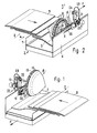
- FIG. 1 and 2 illustrate a device 1 for deflecting of printed products fed in a scale stream 2 3 by one through a feed device 4 (virtually present) and a Wegumbleorgan 5 formed angle, here 90 °.
- the arrows F indicate the direction of conveyance of the printed products.
- Zuier- (4) and away conveyor (5) are by rotating conveyor belts trained, which are not recognizable in the figures.
- the feeder 4 is effective across the width of the removal device 5.
- the removal device 5 is through two side walls 6, 7 designed as a conveyor channel, so that the supplied print products 3 reach the delivery channel via one step.
- the printed products 3 with fed open side and in a scaled Formation and with the head or foot edge through the conveyor 5 scaled with a 90 ° change of direction from the Diverted area.
- the axis of rotation of the Guide element 8 is at right angles to the conveying direction F of the conveying organ 5; however, it could also be a pointed or obtuse angle with the conveying direction F of the conveying member 5 form.
- the rotating body 10 are on the base of the conical Guide organ 8 strung together along the base circumference and freely rotatable about a perpendicular to the axis of rotation of the Axis 8 arranged axis mounted (see also Fig. 3, 4th and 5).
- the rotating body 10 are spherical and have a bore 11 through which a concentric to Rotation axis of the guide member 8 clamped ring 12 made of steel runs.
- the ring 12 is connected to the guide element 8 screwable ring-shaped holding element 13 in between spoke-like ribs 28 on the base of the guide member 8 trained recess 14 arranged.
- a plurality of spherical rotary bodies 10 are mounted in a row on the ring 12.
- the rotating bodies 10 could also be barrel-shaped with an outward curvature, so that they leave no traces or markings on the printed products 3 or that a rolling effect can occur on the printed products 3 when the guide member 8 is rotated.
- the rotary body 10 are surrounded by a projecting annular bead 15, which is formed, for example, from an O-ring and has favorable friction properties with regard to transport of the printed products 3 when deflecting or. Transporting the printed products 3 in the deflection area.
- the guide element 8 is driven via the rotary body 10.
- the surface of the rotating body 10 could be provided with a rubber-containing layer, which favors the deflection process.
- the rotating bodies are advantageously made of plastic, but could also be made of a metallic or other, preferably dirt-repellent material.
- the guide element 8 is advantageously hollow and has an inner hub 16 in which a shaft 17 is fastened. The end of the shaft 17 protruding from the guide element 8 is mounted in an axially immovable and freely rotatable manner in a bearing housing 18 fastened to the free end of the pivotable lever 9 and arranged in the pivot axis of the lever 9.
- the design of the mounting of the bearing housing 18 can be seen in FIG. 4 and, since it is known, does not require any additional explanations.
- the pivot axis of the lever 9 is formed by a hub 26, on which a lever arm 19 projects radially to the pivot axis.
- the hub 26 can be firmly connected to the holder 21 by the clamping lever 24.
- a pneumatically actuated piston-cylinder unit 20 (air spring) is articulated on one side on the lever arm 19.
- the opposite end of the piston-cylinder unit 20 is pivotally connected to a holder 21 fastened to the side wall 6.
- the piston-cylinder unit 20 is connected to a compressed air source which cannot be seen and can be acted upon by an adjustable gas pressure by means of a manually operated reducing valve 22 in the compressed air line 23.
- the contact force of the guide element 8 on the scale flow can be set, for example, depending on the product via the reducing valve 22.
- FIGS. 1, 2 and 3 show a slot 25 in the side wall 6, which runs parallel to the conveying direction F of the conveying member 5 and is penetrated by a rod 27 receiving the hub 26.
- the rod 27 is fixedly connected to the holder 21 designed for one-sided fastening of the piston-cylinder unit 20.
- the guide element 8 can be displaced across the width of the feed element 4.
- the guide element 8 is positioned in an abutting manner on the printed products 3, that is to say is used on the section trailing in the direction of conveyance F in the deflection area (FIG. 1).
- the radius of the guide member 8 is greater than the depth of the channel of the removal member 5 or the tip of the conical guide member 8 projects beyond the step formed between the feed member 4 and the removal member 5.
Landscapes
- Engineering & Computer Science (AREA)
- Mechanical Engineering (AREA)
- Separation, Sorting, Adjustment, Or Bending Of Sheets To Be Conveyed (AREA)
- Printers Or Recording Devices Using Electromagnetic And Radiation Means (AREA)
- Discharge By Other Means (AREA)
- Framework For Endless Conveyors (AREA)
Abstract
Description
- Fig. 1
- eine räumliche Darstellung der erfindungsgemässen Einrichtung,
- Fig. 2
- eine räumliche Darstellung der Einrichtung gemäss Fig. 1 von der Rückseite,
- Fig. 3
- eine auszugsweise Ansicht des Leitorgans der Einrichtung nach den Fig. 1 und 2,
- Fig. 4
- einen Querschnitt durch das Leitorgan gemäss Fig. 3 und
- Fig. 5
- eine Ansicht des Leitorgans an der Rückseite.
Beim dargestellten Ausführungsbeispiel sind die Rotationskörper 10 von einem vorstehenden Ringwulst 15 umgeben, der beispielsweise aus einem O-Ring gebildet ist und günstige Reibungseigenschaften hinsichtlich Transport der Druckprodukte 3 beim Umlenken resp. Transportieren der Druckprodukte 3 im Umlenkbereich aufweist. Der Antrieb des Leitorgans 8 erfolgt über die Rotationskörper 10.
Alternativ könnte anstelle eines Wulstes die Oberfläche der Rotationskörper 10 mit einer gummihaltigen Schicht versehen sein, die den Umlenkvorgang begünstigt.
Die Rotationskörper sind vorteilhaft aus Kunststoff gebildet, könnten jedoch auch aus einem metallischen oder anderen, vorzugsweise schmutzabweisenden Material hergestellt sein.
Das Leitorgan 8 ist vorteilhaft hohl ausgebildet und weist eine innere Nabe 16 auf, in der eine Welle 17 befestigt ist. Das aus dem Leitorgan 8 herausragende Ende der Welle 17 ist in einem an den freien Ende des schwenkbaren Hebels 9 befestigten in der Schwenkachse des Hebels 9 angeordneten Lagergehäuse 18 axial unverschiebbar und frei drehbar gelagert. Die Ausbildung der Lagerung des Lagergehäuses 18 ist der Fig. 4 entnehmbar und braucht -da bekannt- keine zusätzlichen Erklärungen. Die Schwenkachse des Hebels 9 ist durch eine Nabe 26 ausgebildet, an der ein Hebelarm 19 radial zur Schwenkachse absteht. Die Nabe 26 kann durch den Klemmhebel 24 mit dem Halter 21 fest verbunden werden. An dem Hebelarm 19 ist eine pneumatisch betätigbare Kolben-Zylinder-Einheit 20 (Luftfeder) einseitig angelenkt. Das gegenüberliegende Ende der Kolben-Zylinder-Einheit 20 ist schwenkbar mit einem an der Seitenwand 6 befestigten Halter 21 verbunden. Die Kolben-Zylinder-Einheit 20 ist an eine nicht ersichtliche Druckluftquelle angeschlossen und kann durch ein manuell betätigbares Reduzierventil 22 in der Druckluftleitung 23 mit einem einstellbaren Gasdruck beaufschlagt werden. Die Auflagekraft des Leitorgans 8 auf den Schuppenstrom kann bspw. produkteabhängig über das Reduzierventil 22 eingestellt werden. D.h. das Leitorgan 8 kann ausser Betrieb genommen werden. Die Abstandslage des Leitorgans 8 wird gegenüber dem Schuppenstrom automatisch eingestellt. Die Anordnungs- und Gebrauchsweise ist den Fig. 1, 2 und 3 entnehmbar. Diese Figuren zeigen ein parallel zur Förderrichtung F des Wegförderorgans 5 verlaufender Schlitz 25 in der Seitenwand 6, der von einer die Nabe 26 aufnehmenden Stange 27 durchsetzt wird. Die Stange 27 ist mit dem zur einseitigen Befestigung der Kolben-Zylinder-Einheit 20 ausgebildeten Halter 21 fest verbunden. Durch Lösen der Klemmverbindung kann das Leitorgan 8 über die Breite des Zuförderorgans 4 versetzt werden. Erfahrungsgemäss ist es vorteilhaft, wenn das Leitorgan 8 stossend auf die Druckprodukte 3 einwirkend positioniert wird, also auf den in Förderrichtung F im Umlenkbereich nachlaufenden Abschnitt (Fig. 1) einwirkend eingesetzt wird.
Der Halbmesser des Leitorgans 8 ist grösser als die Tiefe des Kanals des Wegförderorgans 5 ausgebildet bzw. die Spitze des kegelförmigen Leitorgans 8 überragt die zwischen Zuförderorgan 4 und Wegförderorgan 5 gebildete Stufe.
Claims (14)
- Einrichtung (1) zum Umlenken von in einem Schuppenstrom zugeführten Druckprodukten (3) um einen durch ein Zuförderorgan (4) und ein Wegförderorgan (5) gebildeten Winkel, wobei das Zuförderorgan (4) wenigstens annähernd über die Breite des Wegförderorgans (5) förderwirksam ist und gegenüberliegend zum Förderende des Zuförderorgans (4), oberhalb des Wegförderorgans (5) wenigstens ein diesem zugeordnetes, kegelförmiges Leitorgan (8) angeordnet ist, das gleichsinnig mit der Förderrichtung (F) des Wegförderorgans (5) drehend einen Förderspalt bildet, dadurch gekennzeichnet, dass das Leitorgan (8) am Basisumfang diesen überstehende Rotationskörper (10) aufweist, die um eine senkrecht zur Drehachse des Leitorgans (8) angeordnete Achse frei drehbar gelagert sind.
- Einrichtung nach Anspruch 1, dadurch gekennzeichnet, dass die Rotationskörper (10) in einer Reihe nebeneinander angeordnet sind.
- Einrichtung nach Anspruch 1 oder 2, dadurch gekennzeichnet, dass die Rotationskörper (10) an einem an der Stirnseite des Leitorgans (8) lösbar befestigten Ring (12) aus Rundstahl gelagert sind.
- Einrichtung nach einem der Ansprüche 1 bis 3, dadurch gekennzeichnet, dass die Rotationskörper (10) kugelförmig ausgebildet sind.
- Einrichtung nach einem der Ansprüche 1 bis 3, dadurch gekennzeichnet, dass die Rotationskörper (10) durch eine fassförmige Wölbung ausgebildet sind.
- Einrichtung nach einem der Ansprüche 1 bis 5, dadurch gekennzeichnet, dass die Rotationskörper (10) an der Oberfläche eine die förderwirksame Reibung begünstigende Rauheit aufweisen.
- Einrichtung nach Anspruch 6, dadurch gekennzeichnet, dass die Rotationskörper (10) einen den Umfang überstehenden Gummiring aufweisen.
- Einrichtung nach einem der Ansprüche 1 bis 7, dadurch gekennzeichnet, dass das Leitorgan (8) im Näherungsbereich des Basisumfangs durch einen steileren Kegelmantel ausgebildet ist.
- Einrichtung nach einem der Ansprüche 1 bis 8, dadurch gekennzeichnet, dass das Leitorgan (8) an der Rückseite in den Umlenkbereich der Druckprodukte (3) ragend an einer Seitenwand des Wegförderorgans (5) befestigt ist.
- Einrichtung nach einem der Ansprüche 1 bis 9, dadurch gekennzeichnet, dass das Leitorgan (8) über die Breite des Zuführorgans (4) entlang der Seitenwand des Wegförderorgans (5) verstellbar befestigt ist.
- Einrichtung nach einem der Ansprüche 1 bis 10, dadurch gekennzeichnet, dass das Leitorgan (8) hohl ausgebildet ist und eine innere Nabe (16) aufweist.
- Einrichtung nach einem der Ansprüche 1 bis 11, dadurch gekennzeichnet, dass das Leitorgan (8) an einem gegen das Eigengewicht beaufschlagten Hebel (9) gelagert ist.
- Einrichtung nach Anspruch 12, dadurch gekennzeichnet, dass der Hebel (9) mit einer gestellseitig abgestützten, einstellbaren pneumatischen Kolben-Zylinder-Einheit (20) verbunden ist.
- Einrichtung nach einem der Ansprüche 9 bis 13, wobei die Druckprodukte (3) über eine eine Stufe bildende Seitenwand (7) des Wegförderers (5) diesem zugeführt werden, dadurch gekennzeichnet, dass der Halbmesser des Leitorgans (8) die durch die Seitenwand (7) gebildete Stufe übersteht.
Priority Applications (3)
| Application Number | Priority Date | Filing Date | Title |
|---|---|---|---|
| EP02405522A EP1375404B1 (de) | 2002-06-24 | 2002-06-24 | Einrichtung zum Umlenken von in einem Schuppenstrom zugeführten Druckprodukte |
| DE50207001T DE50207001D1 (de) | 2002-06-24 | 2002-06-24 | Einrichtung zum Umlenken von in einem Schuppenstrom zugeführten Druckprodukte |
| AT02405522T ATE327958T1 (de) | 2002-06-24 | 2002-06-24 | Einrichtung zum umlenken von in einem schuppenstrom zugeführten druckprodukte |
Applications Claiming Priority (1)
| Application Number | Priority Date | Filing Date | Title |
|---|---|---|---|
| EP02405522A EP1375404B1 (de) | 2002-06-24 | 2002-06-24 | Einrichtung zum Umlenken von in einem Schuppenstrom zugeführten Druckprodukte |
Publications (2)
| Publication Number | Publication Date |
|---|---|
| EP1375404A1 true EP1375404A1 (de) | 2004-01-02 |
| EP1375404B1 EP1375404B1 (de) | 2006-05-31 |
Family
ID=29716995
Family Applications (1)
| Application Number | Title | Priority Date | Filing Date |
|---|---|---|---|
| EP02405522A Expired - Lifetime EP1375404B1 (de) | 2002-06-24 | 2002-06-24 | Einrichtung zum Umlenken von in einem Schuppenstrom zugeführten Druckprodukte |
Country Status (3)
| Country | Link |
|---|---|
| EP (1) | EP1375404B1 (de) |
| AT (1) | ATE327958T1 (de) |
| DE (1) | DE50207001D1 (de) |
Cited By (3)
| Publication number | Priority date | Publication date | Assignee | Title |
|---|---|---|---|---|
| EP2055660A1 (de) * | 2007-11-01 | 2009-05-06 | Ferag AG | Vorrichtung zum getakteten Umlenken von flächigen Gegenständen |
| NL1034705C2 (nl) * | 2007-11-15 | 2009-05-18 | Buhrs Zaandam Bv | Inrichting en werkwijze voor het overbrengen van producten van een eerste op een tweede transporteur. |
| WO2010012609A3 (de) * | 2008-07-31 | 2010-03-25 | Windmöller & Hölscher Kg | Verfahren und vorrichtung zum transport von flachen werkstücken |
Families Citing this family (1)
| Publication number | Priority date | Publication date | Assignee | Title |
|---|---|---|---|---|
| CH702390A1 (de) | 2009-12-02 | 2011-06-15 | Ferag Ag | Verfahren und vorrichtung zum umlagern eines förderstroms aus flexiblen flachen gegenständen. |
Citations (1)
| Publication number | Priority date | Publication date | Assignee | Title |
|---|---|---|---|---|
| CH617408A5 (de) * | 1977-05-27 | 1980-05-30 | Ferag Ag |
-
2002
- 2002-06-24 AT AT02405522T patent/ATE327958T1/de not_active IP Right Cessation
- 2002-06-24 EP EP02405522A patent/EP1375404B1/de not_active Expired - Lifetime
- 2002-06-24 DE DE50207001T patent/DE50207001D1/de not_active Expired - Fee Related
Patent Citations (1)
| Publication number | Priority date | Publication date | Assignee | Title |
|---|---|---|---|---|
| CH617408A5 (de) * | 1977-05-27 | 1980-05-30 | Ferag Ag |
Cited By (5)
| Publication number | Priority date | Publication date | Assignee | Title |
|---|---|---|---|---|
| EP2055660A1 (de) * | 2007-11-01 | 2009-05-06 | Ferag AG | Vorrichtung zum getakteten Umlenken von flächigen Gegenständen |
| US7758043B2 (en) | 2007-11-01 | 2010-07-20 | Ferag Ag | Apparatus for the timed deflection of planar objects |
| NL1034705C2 (nl) * | 2007-11-15 | 2009-05-18 | Buhrs Zaandam Bv | Inrichting en werkwijze voor het overbrengen van producten van een eerste op een tweede transporteur. |
| WO2010012609A3 (de) * | 2008-07-31 | 2010-03-25 | Windmöller & Hölscher Kg | Verfahren und vorrichtung zum transport von flachen werkstücken |
| DE102009000893B4 (de) * | 2008-07-31 | 2015-03-19 | Windmöller & Hölscher Kg | Verfahren und Vorrichtung zum Transport von flachen Werkstücken |
Also Published As
| Publication number | Publication date |
|---|---|
| DE50207001D1 (de) | 2006-07-06 |
| EP1375404B1 (de) | 2006-05-31 |
| ATE327958T1 (de) | 2006-06-15 |
Similar Documents
| Publication | Publication Date | Title |
|---|---|---|
| EP1686084B1 (de) | Einrichtung zum Zusammentragen von Druckbogen an einer Förderstrecke einer umlaufenden Fördervorrichtung | |
| DE1486744B1 (de) | Zusammentragmaschine fuer Druckbogen | |
| DE3135588C2 (de) | Vorrichtung zum Vereinzeln von Bogen von einem Stapel, insbesondere für eine Zusammentragmaschine | |
| DE2838896C2 (de) | ||
| DE3511897A1 (de) | Vorrichtung zum seitlichen ausrichten von bogen | |
| DE3107551C2 (de) | Vorrichtung zum Stapeln von flachen Gegenständen | |
| EP1375404A1 (de) | Einrichtung zum Umlenken von in einem Schuppenstrom zugeführten Druckprodukte | |
| EP0771675A1 (de) | Vorrichtung zur Entnahme von rittlings transportierten Druckprodukten | |
| EP0755886A1 (de) | Vorrichtung zum Zubringen von Druckereiprodukten zu einer Weiterverarbeitungsstelle | |
| DE2162265C2 (de) | Vorrichtung zum Abziehen jeweils eines einzelnen dünnen flachen Gegenstandes, insbesondere einer Karte, von einem Stapel und zum Fördern des abgezogenen Gegenstandes im wesentlichen senkrecht zum Stapel | |
| EP2179952B1 (de) | Verfahren für das klebeweise Vereinen zweier flacher Produkte, insbesondere Druckerzeugnisse mit einem weiteren zugeführten Druckprodukt oder dgl. | |
| DE1254158B (de) | Vorrichtung zum Vereinzeln und Abtransportieren des jeweils vordersten Blattes eines Blattstapels | |
| DE2452052A1 (de) | Verfahren und vorrichtung zum loesen und trennen eines bogens vom anlegestapel von bogen-rotationsdruckmaschinen | |
| DE2818700C2 (de) | ||
| EP0721903A1 (de) | Vorrichtung zum Öffnen von Druckereiprodukten und Einrichtung zum Verarbeiten von Druckereiprodukten | |
| DE1205113B (de) | Vorrichtung zum Vereinzeln und Abfoerdern des jeweils untersten Bogens eines Bogenstapels | |
| EP0903308B1 (de) | Zellenrad zur Uebergabe von Gegenständen von einem ersten Fördermittel an ein zweites Fördermittel | |
| DE3917072A1 (de) | Vorrichtung zum fliessenden transport von bogen | |
| EP0887295A2 (de) | Vorrichtung zum Unterteilen einer Papierbahn | |
| DD146575A1 (de) | Vorrichtung zum transportieren und foerdern von profilierten werkstuecken | |
| DE19802085C2 (de) | Anlegetisch | |
| DE2425736C3 (de) | Vorrichtung zum aufeinanderfolgenden Zuführen von Aufzeichnungsblättern | |
| DE19954119B4 (de) | Bogenführungseinrichtung | |
| DE1054905B (de) | Foerdereinrichtung mit zwei in Foerderrichtung hintereinander geschalteten Foerderbaendern | |
| DE477607C (de) | Vorrichtung zur Herstellung wechselweise ineinandergreifender Schichten gefalteter Zigarettenpapierblaetter |
Legal Events
| Date | Code | Title | Description |
|---|---|---|---|
| PUAI | Public reference made under article 153(3) epc to a published international application that has entered the european phase |
Free format text: ORIGINAL CODE: 0009012 |
|
| AK | Designated contracting states |
Kind code of ref document: A1 Designated state(s): AT BE CH CY DE DK ES FI FR GB GR IE IT LI LU MC NL PT SE TR |
|
| AX | Request for extension of the european patent |
Extension state: AL LT LV MK RO SI |
|
| 17P | Request for examination filed |
Effective date: 20040608 |
|
| AKX | Designation fees paid |
Designated state(s): AT BE CH CY DE DK ES FI FR GB GR IE IT LI LU MC NL PT SE TR |
|
| GRAP | Despatch of communication of intention to grant a patent |
Free format text: ORIGINAL CODE: EPIDOSNIGR1 |
|
| GRAS | Grant fee paid |
Free format text: ORIGINAL CODE: EPIDOSNIGR3 |
|
| GRAA | (expected) grant |
Free format text: ORIGINAL CODE: 0009210 |
|
| AK | Designated contracting states |
Kind code of ref document: B1 Designated state(s): AT BE CH CY DE DK ES FI FR GB GR IE IT LI LU MC NL PT SE TR |
|
| PG25 | Lapsed in a contracting state [announced via postgrant information from national office to epo] |
Ref country code: IT Free format text: LAPSE BECAUSE OF FAILURE TO SUBMIT A TRANSLATION OF THE DESCRIPTION OR TO PAY THE FEE WITHIN THE PRESCRIBED TIME-LIMIT;WARNING: LAPSES OF ITALIAN PATENTS WITH EFFECTIVE DATE BEFORE 2007 MAY HAVE OCCURRED AT ANY TIME BEFORE 2007. THE CORRECT EFFECTIVE DATE MAY BE DIFFERENT FROM THE ONE RECORDED. Effective date: 20060531 Ref country code: IE Free format text: LAPSE BECAUSE OF FAILURE TO SUBMIT A TRANSLATION OF THE DESCRIPTION OR TO PAY THE FEE WITHIN THE PRESCRIBED TIME-LIMIT Effective date: 20060531 Ref country code: GB Free format text: LAPSE BECAUSE OF FAILURE TO SUBMIT A TRANSLATION OF THE DESCRIPTION OR TO PAY THE FEE WITHIN THE PRESCRIBED TIME-LIMIT Effective date: 20060531 Ref country code: NL Free format text: LAPSE BECAUSE OF FAILURE TO SUBMIT A TRANSLATION OF THE DESCRIPTION OR TO PAY THE FEE WITHIN THE PRESCRIBED TIME-LIMIT Effective date: 20060531 Ref country code: FI Free format text: LAPSE BECAUSE OF FAILURE TO SUBMIT A TRANSLATION OF THE DESCRIPTION OR TO PAY THE FEE WITHIN THE PRESCRIBED TIME-LIMIT Effective date: 20060531 |
|
| REG | Reference to a national code |
Ref country code: CH Ref legal event code: EP Ref country code: GB Ref legal event code: FG4D Free format text: NOT ENGLISH |
|
| REG | Reference to a national code |
Ref country code: IE Ref legal event code: FG4D Free format text: LANGUAGE OF EP DOCUMENT: GERMAN |
|
| PG25 | Lapsed in a contracting state [announced via postgrant information from national office to epo] |
Ref country code: BE Free format text: LAPSE BECAUSE OF NON-PAYMENT OF DUE FEES Effective date: 20060630 Ref country code: MC Free format text: LAPSE BECAUSE OF NON-PAYMENT OF DUE FEES Effective date: 20060630 Ref country code: CH Free format text: LAPSE BECAUSE OF NON-PAYMENT OF DUE FEES Effective date: 20060630 Ref country code: LI Free format text: LAPSE BECAUSE OF NON-PAYMENT OF DUE FEES Effective date: 20060630 |
|
| REF | Corresponds to: |
Ref document number: 50207001 Country of ref document: DE Date of ref document: 20060706 Kind code of ref document: P |
|
| PG25 | Lapsed in a contracting state [announced via postgrant information from national office to epo] |
Ref country code: DK Free format text: LAPSE BECAUSE OF FAILURE TO SUBMIT A TRANSLATION OF THE DESCRIPTION OR TO PAY THE FEE WITHIN THE PRESCRIBED TIME-LIMIT Effective date: 20060831 Ref country code: SE Free format text: LAPSE BECAUSE OF FAILURE TO SUBMIT A TRANSLATION OF THE DESCRIPTION OR TO PAY THE FEE WITHIN THE PRESCRIBED TIME-LIMIT Effective date: 20060831 |
|
| PG25 | Lapsed in a contracting state [announced via postgrant information from national office to epo] |
Ref country code: ES Free format text: LAPSE BECAUSE OF FAILURE TO SUBMIT A TRANSLATION OF THE DESCRIPTION OR TO PAY THE FEE WITHIN THE PRESCRIBED TIME-LIMIT Effective date: 20060911 |
|
| PG25 | Lapsed in a contracting state [announced via postgrant information from national office to epo] |
Ref country code: PT Free format text: LAPSE BECAUSE OF FAILURE TO SUBMIT A TRANSLATION OF THE DESCRIPTION OR TO PAY THE FEE WITHIN THE PRESCRIBED TIME-LIMIT Effective date: 20061031 |
|
| NLV1 | Nl: lapsed or annulled due to failure to fulfill the requirements of art. 29p and 29m of the patents act | ||
| GBV | Gb: ep patent (uk) treated as always having been void in accordance with gb section 77(7)/1977 [no translation filed] |
Effective date: 20060531 |
|
| PG25 | Lapsed in a contracting state [announced via postgrant information from national office to epo] |
Ref country code: DE Free format text: LAPSE BECAUSE OF NON-PAYMENT OF DUE FEES Effective date: 20070103 |
|
| REG | Reference to a national code |
Ref country code: CH Ref legal event code: PL |
|
| REG | Reference to a national code |
Ref country code: IE Ref legal event code: FD4D |
|
| PLBE | No opposition filed within time limit |
Free format text: ORIGINAL CODE: 0009261 |
|
| STAA | Information on the status of an ep patent application or granted ep patent |
Free format text: STATUS: NO OPPOSITION FILED WITHIN TIME LIMIT |
|
| EN | Fr: translation not filed | ||
| 26N | No opposition filed |
Effective date: 20070301 |
|
| PG25 | Lapsed in a contracting state [announced via postgrant information from national office to epo] |
Ref country code: AT Free format text: LAPSE BECAUSE OF NON-PAYMENT OF DUE FEES Effective date: 20060624 |
|
| BERE | Be: lapsed |
Owner name: MULLER MARTINI HOLDING A.G. Effective date: 20060630 |
|
| PG25 | Lapsed in a contracting state [announced via postgrant information from national office to epo] |
Ref country code: FR Free format text: LAPSE BECAUSE OF FAILURE TO SUBMIT A TRANSLATION OF THE DESCRIPTION OR TO PAY THE FEE WITHIN THE PRESCRIBED TIME-LIMIT Effective date: 20070309 Ref country code: GR Free format text: LAPSE BECAUSE OF FAILURE TO SUBMIT A TRANSLATION OF THE DESCRIPTION OR TO PAY THE FEE WITHIN THE PRESCRIBED TIME-LIMIT Effective date: 20060901 |
|
| PG25 | Lapsed in a contracting state [announced via postgrant information from national office to epo] |
Ref country code: TR Free format text: LAPSE BECAUSE OF FAILURE TO SUBMIT A TRANSLATION OF THE DESCRIPTION OR TO PAY THE FEE WITHIN THE PRESCRIBED TIME-LIMIT Effective date: 20060531 Ref country code: LU Free format text: LAPSE BECAUSE OF NON-PAYMENT OF DUE FEES Effective date: 20060624 |
|
| PG25 | Lapsed in a contracting state [announced via postgrant information from national office to epo] |
Ref country code: CY Free format text: LAPSE BECAUSE OF FAILURE TO SUBMIT A TRANSLATION OF THE DESCRIPTION OR TO PAY THE FEE WITHIN THE PRESCRIBED TIME-LIMIT Effective date: 20060531 Ref country code: FR Free format text: LAPSE BECAUSE OF FAILURE TO SUBMIT A TRANSLATION OF THE DESCRIPTION OR TO PAY THE FEE WITHIN THE PRESCRIBED TIME-LIMIT Effective date: 20060531 |