EP1369520A2 - Vorrichtung zur kontinuierlichen Nassbehandlung von Garnen - Google Patents
Vorrichtung zur kontinuierlichen Nassbehandlung von Garnen Download PDFInfo
- Publication number
- EP1369520A2 EP1369520A2 EP03076704A EP03076704A EP1369520A2 EP 1369520 A2 EP1369520 A2 EP 1369520A2 EP 03076704 A EP03076704 A EP 03076704A EP 03076704 A EP03076704 A EP 03076704A EP 1369520 A2 EP1369520 A2 EP 1369520A2
- Authority
- EP
- European Patent Office
- Prior art keywords
- yarns
- treatment
- yarn
- bundle
- reactor
- Prior art date
- Legal status (The legal status is an assumption and is not a legal conclusion. Google has not performed a legal analysis and makes no representation as to the accuracy of the status listed.)
- Withdrawn
Links
- 239000012530 fluid Substances 0.000 claims abstract description 32
- 238000000034 method Methods 0.000 claims abstract description 24
- 230000033001 locomotion Effects 0.000 claims description 9
- 230000004913 activation Effects 0.000 claims description 5
- 230000005540 biological transmission Effects 0.000 claims description 4
- 238000000151 deposition Methods 0.000 claims description 3
- 230000003213 activating effect Effects 0.000 claims description 2
- 230000000630 rising effect Effects 0.000 claims 1
- 238000007654 immersion Methods 0.000 abstract 1
- 239000000243 solution Substances 0.000 description 16
- 238000012545 processing Methods 0.000 description 11
- HEMHJVSKTPXQMS-UHFFFAOYSA-M Sodium hydroxide Chemical compound [OH-].[Na+] HEMHJVSKTPXQMS-UHFFFAOYSA-M 0.000 description 5
- 238000005517 mercerization Methods 0.000 description 5
- 229920000742 Cotton Polymers 0.000 description 4
- 241000196324 Embryophyta Species 0.000 description 3
- 239000007795 chemical reaction product Substances 0.000 description 3
- 238000002360 preparation method Methods 0.000 description 3
- 239000000047 product Substances 0.000 description 3
- 239000012670 alkaline solution Substances 0.000 description 2
- 239000003153 chemical reaction reagent Substances 0.000 description 2
- 238000004043 dyeing Methods 0.000 description 2
- 238000005516 engineering process Methods 0.000 description 2
- 230000007613 environmental effect Effects 0.000 description 2
- 238000004519 manufacturing process Methods 0.000 description 2
- 230000002093 peripheral effect Effects 0.000 description 2
- 230000001105 regulatory effect Effects 0.000 description 2
- 235000011121 sodium hydroxide Nutrition 0.000 description 2
- 239000004753 textile Substances 0.000 description 2
- 238000005406 washing Methods 0.000 description 2
- 239000002351 wastewater Substances 0.000 description 2
- XLYOFNOQVPJJNP-UHFFFAOYSA-N water Substances O XLYOFNOQVPJJNP-UHFFFAOYSA-N 0.000 description 2
- 238000004061 bleaching Methods 0.000 description 1
- 239000003518 caustics Substances 0.000 description 1
- 230000001427 coherent effect Effects 0.000 description 1
- 230000001419 dependent effect Effects 0.000 description 1
- 238000009826 distribution Methods 0.000 description 1
- 239000000975 dye Substances 0.000 description 1
- 239000004744 fabric Substances 0.000 description 1
- 150000004677 hydrates Chemical class 0.000 description 1
- 239000007788 liquid Substances 0.000 description 1
- 238000004904 shortening Methods 0.000 description 1
- 238000004513 sizing Methods 0.000 description 1
- 239000000126 substance Substances 0.000 description 1
- 210000003462 vein Anatomy 0.000 description 1
- 238000004804 winding Methods 0.000 description 1
- 210000002268 wool Anatomy 0.000 description 1
Images
Classifications
-
- D—TEXTILES; PAPER
- D06—TREATMENT OF TEXTILES OR THE LIKE; LAUNDERING; FLEXIBLE MATERIALS NOT OTHERWISE PROVIDED FOR
- D06B—TREATING TEXTILE MATERIALS USING LIQUIDS, GASES OR VAPOURS
- D06B17/00—Storing of textile materials in association with the treatment of the materials by liquids, gases or vapours
- D06B17/02—Storing of textile materials in association with the treatment of the materials by liquids, gases or vapours in superimposed, i.e. stack-packed, form; J-boxes
-
- B—PERFORMING OPERATIONS; TRANSPORTING
- B65—CONVEYING; PACKING; STORING; HANDLING THIN OR FILAMENTARY MATERIAL
- B65H—HANDLING THIN OR FILAMENTARY MATERIAL, e.g. SHEETS, WEBS, CABLES
- B65H54/00—Winding, coiling, or depositing filamentary material
- B65H54/76—Depositing materials in cans or receptacles
- B65H54/78—Apparatus in which the depositing device or the receptacle is reciprocated
-
- D—TEXTILES; PAPER
- D06—TREATMENT OF TEXTILES OR THE LIKE; LAUNDERING; FLEXIBLE MATERIALS NOT OTHERWISE PROVIDED FOR
- D06B—TREATING TEXTILE MATERIALS USING LIQUIDS, GASES OR VAPOURS
- D06B3/00—Passing of textile materials through liquids, gases or vapours to effect treatment, e.g. washing, dyeing, bleaching, sizing, impregnating
- D06B3/04—Passing of textile materials through liquids, gases or vapours to effect treatment, e.g. washing, dyeing, bleaching, sizing, impregnating of yarns, threads or filaments
-
- D—TEXTILES; PAPER
- D06—TREATMENT OF TEXTILES OR THE LIKE; LAUNDERING; FLEXIBLE MATERIALS NOT OTHERWISE PROVIDED FOR
- D06B—TREATING TEXTILE MATERIALS USING LIQUIDS, GASES OR VAPOURS
- D06B7/00—Mercerising, e.g. lustring by mercerising
- D06B7/04—Mercerising, e.g. lustring by mercerising of yarns, threads or filaments
-
- B—PERFORMING OPERATIONS; TRANSPORTING
- B65—CONVEYING; PACKING; STORING; HANDLING THIN OR FILAMENTARY MATERIAL
- B65H—HANDLING THIN OR FILAMENTARY MATERIAL, e.g. SHEETS, WEBS, CABLES
- B65H2701/00—Handled material; Storage means
- B65H2701/30—Handled filamentary material
- B65H2701/31—Textiles threads or artificial strands of filaments
Definitions
- the present invention relates to the treatment of yarns with process fluids to give them the desired characteristics before their final use for producing fabrics or other end-products.
- the treatment of yarn with fluids, or more specifically with process liquids such as dyes, bleaches, mercerizing solutions, sizes, etc. is adopted for a wide variety of processings, for different types of fibres such as cotton, wool, silk, linen, etc., which give the yarn the desired characteristics or remove undesired components that reduce their value and the possibility of use for producing end-products.
- this type of treatment can relate to dyeing, mercerizing, bleaching, washing, sizing and so forth.
- Batch processing on yarn is generally extremely onerous due to the considerable labour involved, the low performance of the process fluids, the high plant investments and finally for the environmental implications caused by the reagents discharged with the waste water which consequently require further costs in order to ensure that the drain water is within specification.
- Batch treatment also has the additional problem of quality constancy of the product for each processing batch, depending on the variability of the parameters of each single batch processing such as temperatures, times, concentrations, etc.
- mercerizing is typically effected on yarn in skeins, specifically prepared with a reeling step, subjected to batch mercerization, and subsequently drawn, washed, dried, reeled off and re-prepared in bobbins.
- mercerization consists in treating the yarn with alkaline solutions - typically caustic soda but possibly also with other alkaline hydrates - at a high concentration followed by drawing which basically enhances the yarn considerably, with respect to gloss, higher mechanical properties and improved dyeability, modifying the chemical characteristics and form of the single fibres which make up the yarn.
- the objective of the present invention is to produce a device for the continuous treatment of yarns with process fluids which overcomes the disadvantages of the known devices in the state of the art.
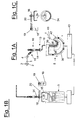
- Figures 1A, 1B and 1C illustrate the constructive and functional characteristics of an illustrative embodiment of the continuous treatment device according to the invention.
- Figure 1A represents a side view of the reactor and its service equipment, whereas figure 1B shows a view from the left and figure 1C the section of the reactor 5.
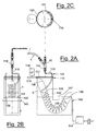
- Figures 2A, B, C illustrate an alternative embodiment of the device according to the invention.
- the treatment illustrated in the embodiments described hereunder can also be effected on a single thread, but for the industrial application of the invention, it is economically more interesting - for the productivity of the device - to operate on a series of threads, preferably joined in a bundle forming a group of threads, generally with from 20 to 200 threads or more also depending on the number of the yarn being processed.
- This expedient in the case of the breakage of one or more single threads 1, prevents them from not continuing their run through the overall machinery but, with continuous feeding, allows them to accumulate in one of the continuous processing machines.
- An alternative for increasing the adherence between the threads of the bundle 1 can be to apply a slight twisting to the bundle itself, a few twists per meter, assembling the creel of the bobbins from which the threads are sent individually, on a rotating support, according to the rope-making technique.
- the feeding of the bundle of threads 1 is obtained with a pair of guiding rolls 2, which rotate at a controlled rate and which determine the linear flow-rate of the bundle of threads 1 being treated, generally at a rate in the order of hundreds of m/minute, sending it to the mercerizing section.
- An important characteristic of the present invention consists in the structure of the reactor in which the treatment of the bundle of threads 1 is effected with the process fluid which, for example, consists of an alkaline solution of sodium hydrate at a high concentration.
- the process fluid which, for example, consists of an alkaline solution of sodium hydrate at a high concentration.
- This operation is carried out in a tank reactor, internally equipped with a saddle-shaped guiding surface of the layer of threads in swirls.
- the reactor 5 is tubular and has the form of a J or asymmetrical U, which means that the bundle of threads continuously moves first with a downward movement in which it is immersed in the bath, followed by an upward movement with emersion from the treatment bath.
- the bundle of threads 1 is deviated with the deviator roll 4 and introduced into the mercerizing reactor 5, by means of a Venturi nozzle 10 fed with a pressurized stream of the treatment fluid, for example the alkaline mercerizing solution.
- the bundle 1 is inserted in the Venturi through one of its side openings 11, in correspondence with the depression of the contracted vein of the driving fluid. The stream therefore sucks up the bundle of threads 1, released by the guiding rolls 2 and subsequently sent to the treatment reactor.
- the bundle of threads 1 is introduced, by means of a distributor 13, with a swirl configuration into the peripheral interspace of the reactor 5.
- the distributor 13 is connected to the final part of the Venturi 10, from which the treatment solution flows entraining with it the bundle of threads 1 at the rate allowed by the guiding rolls 2.
- the connection of the distributor 13 is effected with a vertical cylindrical joint 14, which ends with a deviator tube 15, having an eccentric terminal part capable of rotating around the axis of the cylindrical joint 14, depositing the yarn with swirls in the interspace 30 between the jacket of the reactor 5 and its central sheath.
- a pulley 16 is wedged on the initial cylindrical part of the tube 15, which is rotated by means of a motor 18, on whose axis a similar pulley 19 is assembled, which carries a transmission belt 20.
- the motor 18 is an electric motor piloted in an alternating controlled rotation frequency, clockwise and anticlockwise, according to ⁇ swing angles between 90° and 180°, for example with so-called brushless motors, or with step-by-step motors piloted in frequency by a processor which allows the thread to be deposited at a rate coherent with that of the rolls 2 and with a swirl form having an angular amplitude corresponding to the swing angles of the end of the tube 15.
- Both the Venturi 10 and the upper part of the reactor 5 are positioned with their axis in a vertical or subvertical position, i.e. deviated by a few degrees with respect to the vertical.
- the swirls of the bundle of threads 1 being treated are deposited as a layer 34 which slowly descends onto the saddle 35 of the concave part of an inaccessible sheath 36 and then rises up to the outlet section 38, pulled by the discharge rolls 40.
- Overflow mouths 42 are situated on the outlet edge of the jacket 41 of the treatment reactor, from which the treatment solution, for example the mercerizing solution, overflows into the underlying tank 43 from which the solution is then removed and reused.
- the type of contact and residence times of the yarn of the bundle 1 in the reactor 5 can be regulated and controlled according to a large quantity of variables, with the same linear flow-rate of the bundle of threads 1 being treated.
- the parameters can be - either jointly or separately - the variation of the ⁇ swing angle of the tube 15 of the distributor 13 or the swing frequency, by intervening on the piloting of the activation motor 18, or the delay or the pulling rate with the discharge rolls 40, by intervening on their activation.
- a saddle-shaped guiding surface 35 of the layer of threads in swirls inside the reactor there is a saddle-shaped guiding surface 35 of the layer of threads in swirls.
- it consists for example - but not necessarily - of an inaccessible metallic sheath 36, also J-shaped, which forms an interspace with a circular crown section, with an upper saddle 35 on which the yarn body positioned in swirls moves from the entrance to the exit, in contact with the caustic mercerizing solution which fills the interspace of the reactor up to its overflow level.
- This preferential structure allows the internal volume of the treatment reactor 5 to be reduced to the minimum, together with the quantity and residence time of the treatment solution.
- Said solution percolates in the bundle of threads which, deposited in swirls, for example, in a zigzag arrangement, on the external surface of the sheath 36, slowly moves along the J remaining in contact with the solution for the necessary time.
- the jacket of the reactor 5 is completely open in correspondence with the inlet of the treatment fluid together with the bundle of yarn 1 and the separate outlet of the bundle and solution from the overflow. In some processings, it is preferable to avoid any possible leakages and losses of treatment fluid at the inlet where there can be significant flow-rates.
- Figures 2A, 2B illustrate an alternative embodiment of the device according to the invention with a greater control and seal of the flow at the inlet, for example for the dyeing operations of the yarn.
- Figure 2A represents a side view of the reactor and its service equipment, whereas figure 2B shows its view from the left and figure 2C the upper view of the rotating distributor.
- the tank jacket of the reactor 5 is a casing and in the form of a J, or L, which means that the bundle of threads in continuous is first immersed in and then emerges from the treatment bath.
- the bundle of threads 1 is introduced, by means of a distributor 113, from the Venturi 10, again with a swirl configuration on the saddle-shaped surface inside the reactor 5.
- the reactor is equipped in the upper end of the inlet with a rotating lid 111 with respect to the jacket of the tank 5, which prevents the external leakage of fluid due to the movement of the distributor.
- the distributor 113 is connected to the final part of the Venturi 10 with a vertical cylindrical joint 114, which ends with a deviator tube 115, having an eccentric terminal part capable of rotating around the axis of the cylindrical joint 114, depositing the yarn with swirls.
- a further connection joint 116 is wedged with a circular rotating lid 111, coaxial with the cylindrical joint 114.
- This rotating lid is supported by the jacket with the interposition of low friction sliding devices, already known, and is moved in alternating and controlled rotation by a motor 118, by the interposition of a transmission of the type known in the art, for example a geared transmission 119 which fits into a corresponding toothed section 120 connected to the rotating lid 111.
- the alternating rotating motor can derive from the continuous rotating movement of a motor with the interposition of a classical cinematic connecting rod/handle system.
- the embodiment comprising activation of the distributor 113 with an electric motor 118 piloted in an alternating controlled rotation frequency, clockwise and anticlockwise, according to ⁇ swing angles between 90° and 180°, as described in the embodiment illustrated in figures 1A, B, C, is still useful.
- the swirls of the bundle 1 of threads being treated are deposited in the form of a layer 134 which is deposited in the interspace 130 between the jacket of the tank 5 and the internal surface 136 and which slowly descends onto the saddle 135 of the concave part of said internal surface 136.
- This surface can be either open or inaccessible, with a straight transversal or convex trend of the surface in contact with the layer 134 of yarn which runs along it and rises up to the exit section 138, by the pulling exerted by the discharge rolls 140.
- the surface 136 is shown with a straight transversal trend, whereas in figures 1, it is convex.
- one or more overflow mouths 142 are situated on the outlet edge of the jacket 141 of the treatment reactor, from which the treatment solution overflows into a peripheral channel 143 which collects the overflow fluid and sends it to the underlying tank 144 from which the solution is then removed with a relaunching pump.
- the treatment device of the yarns according to the present invention allows considerable advantages with respect to the known art. Among these special mention should be made to the following characteristics.
- the contact takes place, in fact, in two steps and ensures an effective treatment.
- the first step is effected inside the Venturi nozzle 10 and distributor 13 (or 113) at a high rate: in these devices there is a vortical flow and brusque involvement also of the threads situated inside the bundle 1.
- the second step takes place over a longer period of time and in the interspace of the reactor 5, on the bundle deposited in swirls with a flow in laminar regime in which the permeation and reaction of the solution inside the single threads are gradual and complete.
- the structure of the reaction device 5 also overcomes problems relating to the dimensional variations of the yarn subjected to treatment.
- These variations in length are entirely compensated with the distribution of the bundle 1 in swirls in the reactor with the distributor 13, and by activating the discharge rolls 40 at a linear rate corresponding to that of the initial rolls 2, thus calculating the variation in the shortening due to the mercerization.
- the treatment operations are effected in continuous, and not in small batches, without requiring previous preparation in bobbins or skeins followed by unwinding and re-preparation.
- the continuous processing of the yarn is consequently more economical, both due to the lesser amount of labour used, the high performance of the process fluids and washing water, the higher plant productivity and lower plant investments required with the same productive capacity, and finally fewer environmental problems as a result of the reduced quantity of reagents discharged with the waste water.
- the constancy of the product quality which is obtained with the continuous treatment system according to the present invention is considerably improved, due to the constancy of the parameters of each processing step which can be maintained at the desired temperature, time, concentration values, and so forth.
- the particular conformation of the treatment reactor with a relative double motion regime of the fluid and yarn, a Venturi nozzle and underlying tank, allows the process conditions and times to be regulated within a wide range without influencing the treatment capacity.
Landscapes
- Engineering & Computer Science (AREA)
- Textile Engineering (AREA)
- Chemical & Material Sciences (AREA)
- Materials Engineering (AREA)
- Treatment Of Fiber Materials (AREA)
- Yarns And Mechanical Finishing Of Yarns Or Ropes (AREA)
Applications Claiming Priority (2)
| Application Number | Priority Date | Filing Date | Title |
|---|---|---|---|
| IT2002MI001221A ITMI20021221A1 (it) | 2002-06-05 | 2002-06-05 | Dispositivo per il trattamento in continuo dei filati con fluidi di processo |
| ITMI20021221 | 2002-06-05 |
Publications (2)
| Publication Number | Publication Date |
|---|---|
| EP1369520A2 true EP1369520A2 (de) | 2003-12-10 |
| EP1369520A3 EP1369520A3 (de) | 2005-03-23 |
Family
ID=29434437
Family Applications (1)
| Application Number | Title | Priority Date | Filing Date |
|---|---|---|---|
| EP03076704A Withdrawn EP1369520A3 (de) | 2002-06-05 | 2003-06-02 | Vorrichtung zur kontinuierlichen Nassbehandlung von Garnen |
Country Status (4)
| Country | Link |
|---|---|
| US (1) | US7140207B2 (de) |
| EP (1) | EP1369520A3 (de) |
| CN (1) | CN1287033C (de) |
| IT (1) | ITMI20021221A1 (de) |
Cited By (2)
| Publication number | Priority date | Publication date | Assignee | Title |
|---|---|---|---|---|
| EP1900864A2 (de) | 2006-09-15 | 2008-03-19 | SAVIO MACCHINE TESSILI S.p.A. | Verfahren und Vorrichtung zum kontinuierlichen Mercerisieren von Textilgarnen |
| EP3415674A1 (de) * | 2017-06-13 | 2018-12-19 | Fong's Europe GmbH | Vorrichtung zum abgetafelten ablegen eines laufenden textilwarenstrangs |
Families Citing this family (2)
| Publication number | Priority date | Publication date | Assignee | Title |
|---|---|---|---|---|
| DE102004039674A1 (de) | 2004-08-16 | 2005-11-10 | Siemens Ag | Anordnung zur Signalübertragung zwischen einer ersten Basisstation und einem Funkkommunikationsendgerät |
| US9970141B2 (en) * | 2015-02-18 | 2018-05-15 | Morrison Textile Machinery Company | Apparatus and method for washing an elongate textile article |
Citations (5)
| Publication number | Priority date | Publication date | Assignee | Title |
|---|---|---|---|---|
| US1665624A (en) * | 1926-04-05 | 1928-04-10 | William L Conrad | Processing apparatus |
| US3330134A (en) * | 1965-09-28 | 1967-07-11 | Burlington Industries Inc | Apparatus for the fluid treatment of textiles |
| US3587256A (en) * | 1968-08-16 | 1971-06-28 | Avesta Jernverks Ab | Machine for dyeing textile material |
| US4041559A (en) * | 1973-08-23 | 1977-08-16 | Hoechst Aktiengesellschaft | Process for the continuous wet treatment of textile material in rope form |
| GB2004927A (en) * | 1977-09-30 | 1979-04-11 | Mezzera Spa | Jet dyeing apparatus |
Family Cites Families (55)
| Publication number | Priority date | Publication date | Assignee | Title |
|---|---|---|---|---|
| US42782A (en) * | 1864-05-17 | Improved apparatus for bleaching | ||
| US1371055A (en) * | 1920-12-14 | 1921-03-08 | Robertson Bleachery & Dye Work | Piling device |
| FR543256A (fr) * | 1921-11-07 | 1922-08-30 | Perfectionnements dans la fabrication des fils ou filaments artificiels | |
| DE385158C (de) * | 1922-01-14 | 1923-12-05 | William Porter Dreaper | Vorrichtung zur Herstellung von Stapelfaser nach dem Schleuderspinnverfahren |
| US1555864A (en) * | 1923-04-21 | 1925-10-06 | Coit Johnson F | Machine for mercerizing yarn |
| US1691701A (en) * | 1927-05-17 | 1928-11-13 | Edwin E Carlson | Method of dyeing yarn |
| US1858073A (en) * | 1930-09-15 | 1932-05-10 | Rotary Printing Company | Paper delivery mechanism |
| US1955719A (en) * | 1931-03-21 | 1934-04-17 | American Bemberg Corp | Filament winding and treating |
| FR805799A (fr) | 1936-04-09 | 1936-11-28 | Procédé et dispositif pour le lavage, la désulfuration, le blanchiment et la teinture de filés artificiels | |
| US2725276A (en) * | 1949-10-20 | 1955-11-29 | American Enka Corp | Process and apparatus for treating threads in tubes |
| US2581018A (en) * | 1950-04-28 | 1952-01-01 | E Z Mills Inc | Apparatus for treating textile fabrics |
| US2947595A (en) * | 1955-01-24 | 1960-08-02 | Celanese Corp | Treatment of filamentary materials |
| NL122666C (de) * | 1960-03-11 | |||
| US3064328A (en) * | 1960-09-08 | 1962-11-20 | Lees & Sons Co James | Yarn feeding and storage apparatus |
| US3234627A (en) * | 1962-07-31 | 1966-02-15 | Bancroft & Sons Co J | Dye package |
| US3281913A (en) * | 1964-08-10 | 1966-11-01 | Eastman Kodak Co | Apparatus and method for handling yarn bundles |
| FR1441502A (fr) * | 1965-02-19 | 1966-06-10 | Crylor | Procédé et appareil pour le bambanage de câbles de filaments continus ou de rubans de fibres discontinues |
| US3378898A (en) * | 1965-03-05 | 1968-04-23 | Du Pont | Textile package laydown device |
| US3397437A (en) * | 1966-11-08 | 1968-08-20 | Mcneill Spinning Company Inc | Method and apparatus for conveying yarn |
| GB1199781A (en) | 1967-01-13 | 1970-07-22 | Masao Masuda | Method and Apparatus for Treating Knitted or Woven Material |
| FR1584999A (de) | 1968-03-20 | 1970-01-09 | ||
| DE1913826A1 (de) * | 1968-03-20 | 1969-10-16 | Jean Amengual | Verfahren und Vorrichtung zur automatischen,kontinuierlichen Einfaerbung von Textilfaeden |
| DE1926280A1 (de) * | 1968-05-29 | 1969-12-04 | Masao Masuda | Verfahren und Vorrichtung zum Faerben von textilen Stoffbahnen |
| DE1801976A1 (de) | 1968-10-09 | 1970-05-27 | Glanzstoff Ag | Verfahren und Vorrichtung zum kontinuierlichen,spannungsfreien Fixieren und Schrumpfen von Kabeln aus ungekraeuselten Faeden |
| US3580445A (en) * | 1969-06-16 | 1971-05-25 | Eastman Kodak Co | Guiding apparatus for eliminating entanglement and twist in puddled multifilament yarn |
| US3616663A (en) * | 1969-11-08 | 1971-11-02 | Goro Matsuda | Apparatus for dyeing cloth |
| US3781951A (en) * | 1971-08-30 | 1974-01-01 | Textured Yarn Co | Method and apparatus for compressively crimping textile strands |
| US3767360A (en) * | 1971-11-17 | 1973-10-23 | Du Pont | Process for washing solvent laden filaments |
| BE790904A (fr) * | 1971-11-29 | 1973-03-01 | Corbiere Claude | Procede et dispositif de stockage de fils textiles |
| US3782138A (en) * | 1971-12-29 | 1974-01-01 | Sakai Textile Mfg Co Ltd | Apparatus for treating cloth with liquid |
| US3887347A (en) * | 1974-04-01 | 1975-06-03 | Ppg Industries Inc | Method of packaging glass strand |
| DE2459363C2 (de) | 1974-12-16 | 1983-08-18 | Alfred 4420 Coesfeld Thies Jun. | Vorrichtung zum Naßbehandeln eines strangförmigen textilen Flächengebildes |
| DE2616922A1 (de) | 1976-04-15 | 1977-10-27 | Hacoba Textilmaschinen | Vorrichtung zum behandeln von textilem fadenmaterial, insbesondere mit dampf |
| FR2371539A1 (fr) | 1976-11-19 | 1978-06-16 | Cdb Europ | Procede et dispositif de teinture d'elements filiformes |
| US4074901A (en) * | 1977-03-31 | 1978-02-21 | Frank Catallo | Folder for web materials |
| US4080772A (en) * | 1977-05-06 | 1978-03-28 | Champion International Corporation | Apparatus for depositing materials in a container |
| US4120143A (en) * | 1977-10-25 | 1978-10-17 | Champion International Corporation | Fluid self-twist spinning apparatus |
| DE3013747A1 (de) * | 1980-04-10 | 1981-10-15 | H. Krantz Gmbh & Co, 5100 Aachen | Vorrichtung zur nassbehandlung, insbesondere zum faerben von kontinuierlichen im kreislauf gefuehrtem strangfroemigem textilgut |
| GB2074132A (en) * | 1980-04-17 | 1981-10-28 | Aei | Coiling strand material into packages |
| US4408378A (en) * | 1980-11-21 | 1983-10-11 | Associated Electrical Industries Limited | Apparatus for forming a filament coil of figure of eight conformation |
| SE441683B (sv) * | 1983-03-18 | 1985-10-28 | Adcon Ab | Forfarande vid fergbehandling av textila material samt anvendning av en anordning for genomforande av forfarandet |
| US4654910A (en) * | 1984-09-28 | 1987-04-07 | Ube Industries, Ltd. | Spun yarn piling and cleaning method |
| JPS6183310A (ja) * | 1984-09-28 | 1986-04-26 | Ube Ind Ltd | 湿式紡糸における製品引取り方法 |
| JPS61124479A (ja) * | 1984-11-19 | 1986-06-12 | Teijin Ltd | 糸条の容器への収容方法及び装置 |
| US4837903A (en) * | 1985-01-30 | 1989-06-13 | Mitsubishi Rayon Company Ltd. | Method and apparatus for producing slub yarn |
| IT1205003B (it) * | 1987-05-07 | 1989-03-10 | Mcs Off Mecc Spa | Procedimento e macchina per il trattamento,in particolare la tintura discontinua,di tessuti in falde |
| DE3724075A1 (de) * | 1987-07-21 | 1989-02-02 | Hoechst Ag | Verfahren zum behandeln von textilgut in jet-faerbemaschinen sowie vorrichtung zur durchfuehrung desselben |
| JPH01118662A (ja) | 1987-10-27 | 1989-05-11 | Yoshida Kogyo Kk <Ykk> | テープ堆積循環型染色機 |
| JPH01321972A (ja) * | 1988-06-20 | 1989-12-27 | Toray Ind Inc | 布帛の流体処理方法およびその装置 |
| JP2673701B2 (ja) * | 1988-06-29 | 1997-11-05 | 東洋紡績株式会社 | 繊維品の処理装置 |
| US5046209A (en) * | 1990-04-20 | 1991-09-10 | Keiltex Corporation | Batch dyeing and washing apparatus and method |
| US5621937A (en) * | 1994-04-04 | 1997-04-22 | S. Sclavos, S.A. | Jet dyeing apparatus and method |
| WO1997011886A1 (en) * | 1995-09-27 | 1997-04-03 | Tubular Textile Machinery Corporation | Fabric distributor |
| JP3872899B2 (ja) * | 1997-12-25 | 2007-01-24 | 出光興産株式会社 | テープ類の梱包方法 |
| TW420771B (en) * | 1999-08-14 | 2001-02-01 | Ibm | Electronic control system for controlling the function of a processing system and method for managing system fault situations of the electronic control system |
-
2002
- 2002-06-05 IT IT2002MI001221A patent/ITMI20021221A1/it unknown
-
2003
- 2003-05-28 US US10/446,905 patent/US7140207B2/en not_active Expired - Fee Related
- 2003-06-02 EP EP03076704A patent/EP1369520A3/de not_active Withdrawn
- 2003-06-05 CN CNB031411851A patent/CN1287033C/zh not_active Expired - Fee Related
Patent Citations (5)
| Publication number | Priority date | Publication date | Assignee | Title |
|---|---|---|---|---|
| US1665624A (en) * | 1926-04-05 | 1928-04-10 | William L Conrad | Processing apparatus |
| US3330134A (en) * | 1965-09-28 | 1967-07-11 | Burlington Industries Inc | Apparatus for the fluid treatment of textiles |
| US3587256A (en) * | 1968-08-16 | 1971-06-28 | Avesta Jernverks Ab | Machine for dyeing textile material |
| US4041559A (en) * | 1973-08-23 | 1977-08-16 | Hoechst Aktiengesellschaft | Process for the continuous wet treatment of textile material in rope form |
| GB2004927A (en) * | 1977-09-30 | 1979-04-11 | Mezzera Spa | Jet dyeing apparatus |
Cited By (2)
| Publication number | Priority date | Publication date | Assignee | Title |
|---|---|---|---|---|
| EP1900864A2 (de) | 2006-09-15 | 2008-03-19 | SAVIO MACCHINE TESSILI S.p.A. | Verfahren und Vorrichtung zum kontinuierlichen Mercerisieren von Textilgarnen |
| EP3415674A1 (de) * | 2017-06-13 | 2018-12-19 | Fong's Europe GmbH | Vorrichtung zum abgetafelten ablegen eines laufenden textilwarenstrangs |
Also Published As
| Publication number | Publication date |
|---|---|
| EP1369520A3 (de) | 2005-03-23 |
| US20030226381A1 (en) | 2003-12-11 |
| CN1287033C (zh) | 2006-11-29 |
| US7140207B2 (en) | 2006-11-28 |
| ITMI20021221A1 (it) | 2003-12-05 |
| CN1469000A (zh) | 2004-01-21 |
Similar Documents
| Publication | Publication Date | Title |
|---|---|---|
| IL44523A (en) | Machines for continously spinning and treating rayon-viscose filaments and yarns | |
| US2002996A (en) | Continue process and apparatus | |
| US3510251A (en) | Method and apparatus for treating textile material with liquid | |
| US4153961A (en) | Method and apparatus for randomly dyeing textile yarns in a continuous system | |
| KR20180027412A (ko) | 섬유 기재의 처리 방법 및 상기 방법을 실현하기 위한 장치 | |
| US7140207B2 (en) | Device for the continuous treatment of yarns with process fluids | |
| JP2005501985A (ja) | 布地一般の仕上げ処理装置および方法 | |
| US7090702B2 (en) | Continuous treatment system of yarns with process fluids, particularly for their mercerization under tension | |
| EP1369521B1 (de) | Verfahren zur kontinuierlichen Merzerisierung von Textilgarnen | |
| JP2779899B2 (ja) | スライバーの連続マーセル加工方法及び加工装置 | |
| KR100550686B1 (ko) | 연속 성형체의 생성 방법 및 장치 | |
| EP1900864B1 (de) | Verfahren und Vorrichtung zum kontinuierlichen Mercerisieren von Textilgarnen | |
| US3766581A (en) | Process for continuously treating thread | |
| US5359743A (en) | Continuous process and installation for treating textile fabric webs | |
| US2974363A (en) | Method of and apparatus for the continuous production of synthetic fibers | |
| US3605146A (en) | Process and apparatus for automatically and continuously dyeing a textile thread | |
| GB2092191A (en) | Wet-heat treating textiles | |
| GB936758A (en) | Method and apparatus for wet spinning polyacrylonitrile filaments | |
| US3983722A (en) | Apparatus for the continuous treatment of threads | |
| US241464A (en) | wilkinson | |
| US3024493A (en) | Adjustably shielded suction drum for circulating bath liquid | |
| US1494841A (en) | Manufacturing artificial silk threads | |
| CN221276058U (zh) | 一种退浆清洗装置 | |
| US977863A (en) | Apparatus for the manufacture of artificial silk. | |
| CN215713925U (zh) | 一种环保型面料生产试剂循环处理装置 |
Legal Events
| Date | Code | Title | Description |
|---|---|---|---|
| PUAI | Public reference made under article 153(3) epc to a published international application that has entered the european phase |
Free format text: ORIGINAL CODE: 0009012 |
|
| AK | Designated contracting states |
Kind code of ref document: A2 Designated state(s): AT BE BG CH CY CZ DE DK EE ES FI FR GB GR HU IE IT LI LU MC NL PT RO SE SI SK TR |
|
| AX | Request for extension of the european patent |
Extension state: AL LT LV MK |
|
| PUAL | Search report despatched |
Free format text: ORIGINAL CODE: 0009013 |
|
| AK | Designated contracting states |
Kind code of ref document: A3 Designated state(s): AT BE BG CH CY CZ DE DK EE ES FI FR GB GR HU IE IT LI LU MC NL PT RO SE SI SK TR |
|
| AX | Request for extension of the european patent |
Extension state: AL LT LV MK |
|
| RIC1 | Information provided on ipc code assigned before grant |
Ipc: 7D 06B 7/04 B Ipc: 7D 06B 17/02 B Ipc: 7D 06B 3/04 A |
|
| 17P | Request for examination filed |
Effective date: 20050509 |
|
| AKX | Designation fees paid |
Designated state(s): AT BE BG CH CY CZ DE DK EE ES FI FR GB GR HU IE IT LI LU MC NL PT RO SE SI SK TR |
|
| 17Q | First examination report despatched |
Effective date: 20060704 |
|
| GRAP | Despatch of communication of intention to grant a patent |
Free format text: ORIGINAL CODE: EPIDOSNIGR1 |
|
| STAA | Information on the status of an ep patent application or granted ep patent |
Free format text: STATUS: THE APPLICATION IS DEEMED TO BE WITHDRAWN |
|
| 18D | Application deemed to be withdrawn |
Effective date: 20070613 |