EP1369211B2 - Vorrichtung zum Führen und Zurückholen eines Schlauches eines Industrieroboters - Google Patents
Vorrichtung zum Führen und Zurückholen eines Schlauches eines Industrieroboters Download PDFInfo
- Publication number
- EP1369211B2 EP1369211B2 EP03011402.9A EP03011402A EP1369211B2 EP 1369211 B2 EP1369211 B2 EP 1369211B2 EP 03011402 A EP03011402 A EP 03011402A EP 1369211 B2 EP1369211 B2 EP 1369211B2
- Authority
- EP
- European Patent Office
- Prior art keywords
- hose
- channel
- guiding
- tension spring
- holder
- Prior art date
- Legal status (The legal status is an assumption and is not a legal conclusion. Google has not performed a legal analysis and makes no representation as to the accuracy of the status listed.)
- Expired - Lifetime
Links
- 230000007704 transition Effects 0.000 claims description 3
- 230000001681 protective effect Effects 0.000 description 21
- 238000013459 approach Methods 0.000 description 3
- 239000012530 fluid Substances 0.000 description 2
- 238000005452 bending Methods 0.000 description 1
- 238000001816 cooling Methods 0.000 description 1
- 239000012809 cooling fluid Substances 0.000 description 1
- 230000006735 deficit Effects 0.000 description 1
- 239000007787 solid Substances 0.000 description 1
Images


Classifications
-
- B—PERFORMING OPERATIONS; TRANSPORTING
- B25—HAND TOOLS; PORTABLE POWER-DRIVEN TOOLS; MANIPULATORS
- B25J—MANIPULATORS; CHAMBERS PROVIDED WITH MANIPULATION DEVICES
- B25J19/00—Accessories fitted to manipulators, e.g. for monitoring, for viewing; Safety devices combined with or specially adapted for use in connection with manipulators
- B25J19/0025—Means for supplying energy to the end effector
-
- F—MECHANICAL ENGINEERING; LIGHTING; HEATING; WEAPONS; BLASTING
- F16—ENGINEERING ELEMENTS AND UNITS; GENERAL MEASURES FOR PRODUCING AND MAINTAINING EFFECTIVE FUNCTIONING OF MACHINES OR INSTALLATIONS; THERMAL INSULATION IN GENERAL
- F16L—PIPES; JOINTS OR FITTINGS FOR PIPES; SUPPORTS FOR PIPES, CABLES OR PROTECTIVE TUBING; MEANS FOR THERMAL INSULATION IN GENERAL
- F16L3/00—Supports for pipes, cables or protective tubing, e.g. hangers, holders, clamps, cleats, clips, brackets
- F16L3/26—Supports for pipes, cables or protective tubing, e.g. hangers, holders, clamps, cleats, clips, brackets specially adapted for supporting the pipes all along their length, e.g. pipe channels or ducts
-
- H—ELECTRICITY
- H02—GENERATION; CONVERSION OR DISTRIBUTION OF ELECTRIC POWER
- H02G—INSTALLATION OF ELECTRIC CABLES OR LINES, OR OF COMBINED OPTICAL AND ELECTRIC CABLES OR LINES
- H02G11/00—Arrangements of electric cables or lines between relatively-movable parts
-
- H—ELECTRICITY
- H02—GENERATION; CONVERSION OR DISTRIBUTION OF ELECTRIC POWER
- H02G—INSTALLATION OF ELECTRIC CABLES OR LINES, OR OF COMBINED OPTICAL AND ELECTRIC CABLES OR LINES
- H02G3/00—Installations of electric cables or lines or protective tubing therefor in or on buildings, equivalent structures or vehicles
- H02G3/02—Details
- H02G3/04—Protective tubing or conduits, e.g. cable ladders or cable troughs
- H02G3/0462—Tubings, i.e. having a closed section
- H02G3/0481—Tubings, i.e. having a closed section with a circular cross-section
-
- Y—GENERAL TAGGING OF NEW TECHNOLOGICAL DEVELOPMENTS; GENERAL TAGGING OF CROSS-SECTIONAL TECHNOLOGIES SPANNING OVER SEVERAL SECTIONS OF THE IPC; TECHNICAL SUBJECTS COVERED BY FORMER USPC CROSS-REFERENCE ART COLLECTIONS [XRACs] AND DIGESTS
- Y10—TECHNICAL SUBJECTS COVERED BY FORMER USPC
- Y10T—TECHNICAL SUBJECTS COVERED BY FORMER US CLASSIFICATION
- Y10T74/00—Machine element or mechanism
- Y10T74/20—Control lever and linkage systems
- Y10T74/20207—Multiple controlling elements for single controlled element
- Y10T74/20305—Robotic arm
- Y10T74/20311—Robotic arm including power cable or connector
Definitions
- the invention relates to a device for guiding and retrieving at least one hose of an industrial robot.
- Such devices for guiding a hose are provided in machines, systems, but especially robots, for guiding a protective tube in the supply lines, such as power and control cables, fluids, such as cooling fluids or gaseous fluids to produce an over- or a negative pressure are.
- the invention finds here its preferred field of application.
- Such hoses are guided, for example, in a robot along the parts of the robot, as along the robot arm and along the rocker. Due to the movements of the robot, in particular the robot hand, which usually carries a tool that is supplied by the supply line, the supply lines and the protective tube must be able to perform length compensation movements.
- the protective tube is surrounded by a helical tension spring, which on the one hand finds a solid part on an abutment on the protective tube itself, on the other hand on a robot.
- the guide is either via a separate slide or more bearings that are pipe-shaped and in which or along which the protective hose can slide.
- the DE 201 12 491 U1 shows an industrial robot with a generic wiring, in which a protective tube is surrounded by a coil spring, on the one hand finds an abutment on a robot-fixed part, on the other hand on a ring attached to the hose.
- the FR 2 778 449 shows an elongated cable nut with side receptacles for individual cables. This serves only for the extended support of the cable, on which no train or the like is exercised.
- the invention has for its object to provide a device for guiding and length compensation of a hose of an industrial robot in a compact and simple design that allows a far-reaching accurate guiding and retrieving the hose in a small space.
- the object is achieved with a device for guiding and retrieving at least one hose of an industrial robot, which has the features of claim 1.
- the width of the lateral opening is such that it exceeds, preferably significantly exceeds, the transverse dimension of the supply lines routed through the protective tube, in order to prevent the supply lines from bending over.
- the channel has a circular cross-section.
- the invention further provides that the channel is provided in the region of its longitudinal opening with laterally extending longitudinal approaches, in particular, the longitudinal approaches in the region of their free longitudinal edges have a greater relative distance than in their transition region to the channel.
- the protective tube for exerting a bias against movement of the part to which it leads the supply line is surrounded by a spring
- an abutment for a spring surrounding the hose is connected to the channel, in particular the abutment is formed as a circumferential groove, into which engages an end of the spring.
- Another abutment is the spring on a side facing away from the tool region of the protective tube, for example by there is a wear ring is placed.
- trumpet-like support for the hose is provided according to the invention, which is designed according to the invention as a hinged clamp, so that the hose can be inserted laterally in the unfolded clamp and is completely surrounded by this after closing.
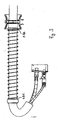
- FIG. 1 shows parts of a robot 1, namely a rocker 1.1, a robot arm 1.2 and a robot hand 1.3.
- This carries a in the illustrated embodiment motor with a hollow axle for the last hand axis, wherein the flange 1.4.1 a tool is attached.
- the hand 1.3 could alternatively hold a tool immediately.
- the supply of the motor 1.4 or a tool, such as electrical energy supply, supply of media, such as cooling media, but also "supply" with negative pressure, so exerting a vacuum of existing on a tool 1.4 suction cups, via supply lines 1.5, in a protective 1.6 are guided.
- the supply lines 1.5 open in a connection plate 1.7, which are fixed on the robot arm 1.2 and connections 1.7.1 for connection to the base (not shown) of the robot 1 further supply lines along the rocker 1.1.
- the - partially - shown robot is a Palletierroboter.
- the invention can also be used in other conventional industrial robots.
- a device 2 for guiding the hose 1.6 is arranged on the upper side 1.2.1 of the robot arm 1.2.
- This has two fixed to the top 1.2.1 of the robot arm 1.2 webs 2.1, which carry a support plate 2.2, on which in turn is provided with a lateral longitudinal opening 2.3 channel 2.4 is held.
- the channel 2.4 is provided at its edges delimiting the openings with lateral longitudinal projections which expand outward, ie have a greater relative distance at their free outer edge than at their transition region to the actual channel 2.4.
- the protective tube 1.6 is surrounded by a helical tension spring 1.8.
- the tool 1.4 facing away from the rear end, it is provided with a wear ring 1.9, where the tension spring 1.8 finds one of its abutment.
- a trumpet-like clamp 2.6 At the front end of the support plate 2.2 is connected to this a trumpet-like clamp 2.6, through which the protective tube 1.6 is led out to the tool 1.4 of the channel 2.4.
- a fixed abutment for the tension spring 1.8 is formed, for example in the form of an annular groove in which the clamp 2.6 facing the end of the spring engages 1.8 and thus held laterally.
- the supply lines run after the end of the protective tube and thereby change their radius of curvature between the outlet of the protective tube 1.6 and the connection plate 1.7.
- the supply lines 1.5 move back to the end of the protective tube 1.6 and return to their original curvature.
- the respective last end-side turn 1.8.1, 1.8.2 of the tension spring 1.8 is formed in each case in an axially perpendicular plane, so that the end turn 1.8.1 rests almost vollringförmig the wear ring 1.9.
- the opposite end turn 1.8.2 of the tension spring 1.8 is located in an annular groove 2.7.1 of an insert part 2.7 of the clamp 2.6, in which the tension spring 1.8 passes over a recess 2.7.2 and is engaged in the end turn 1.8.2.
- the insert 2.7 is held in the central region 2.6.1 of the clamp 2.6 by this (after closing the same) at least in the axial direction positively.
- the invention provides a compact device, designed in a unit, for guiding a hose, such as here a protective hose for supply lines of a robot, which enables precise guiding of the hose and retrieval in a small space requirement.
Landscapes
- Engineering & Computer Science (AREA)
- Mechanical Engineering (AREA)
- General Engineering & Computer Science (AREA)
- Robotics (AREA)
- Architecture (AREA)
- Civil Engineering (AREA)
- Structural Engineering (AREA)
- Manipulator (AREA)
- Supports For Pipes And Cables (AREA)
Description
- Die Erfindung betrifft eine Vorrichtung zum Führen und Zurückholen mindestens eines Schlauches eines Industrieroboters.
- Derartige Vorrichtungen zum Führen eines Schlauches werden bei Maschinen, Anlagen, insbesondere aber Robotern, zum Führen eines Schutzschlauches vorgesehen, in dem Versorgungsleitungen, wie Energie- und Steuerkabel, Fluide, wie Kühlflüssigkeiten oder aber gasförmige Fluide zur Erzeugung eines Über- oder auch eines Unterdrucks geführt sind. Die Erfindung findet hier ihr bevorzugtes Anwendungsgebiet.
- Derartige Schläuche sind beispielsweise bei einem Roboter entlang der Teile des Roboters, wie entlang des Roboterarms und entlang der Schwinge, geführt. Aufgrund der Bewegungen des Roboters, insbesondere auch der Roboterhand, die in der Regel ein Werkzeug trägt, das durch die Versorgungsleitung versorgt ist, müssen die Versorgungsleitungen und der Schutzschlauch Längenausgleichsbewegungen durchführen können. Üblicherweise ist der Schutzschlauch durch eine schraubenartige Spannfeder umgeben, die einerseits an einem Widerlager am Schutzschlauch selbst, andererseits an einem Roboter festen Teil findet. Die Führung erfolgt entweder über einen separaten Schlitten oder mehrere Lagerstellen, die rohrstutzenförmig ausgebildet sind und in denen oder entlang derer der Schutzschlauch gleiten kann.
- Nachteilig ist bei derartigen Führungsvorrichtungen, dass die Schlittenführungen aufwendig sind und die mehrfache Lagerungen ungenau sind, d.h. sie ermöglichen dem Führungsschlauch und damit den Versorgungsleitungen relativ große Ausweichbewegungen und hierdurch ist eine Beschädigungsgefahr für den Schlauch und auch die Versorgungsleitung gegeben. Darüber hinaus sind beide Ausgestaltungen teuer und sperrig.
- Die
DE 201 12 491 U1 zeigt einen Industrieroboter mit einer gattungsgemäßen Leitungsführung, bei der ein Schutzschlauch von einer Schraubenfeder umgeben ist, die einerseits ein Widerlager an einem roboterfesten Teil findet, anderseits an einer an dem Schlauch befestigten Ring. Es besteht die Gefahr, dass nach Herausziehen des Schlauches und Komprimierung der Feder bei Entlastung bzw. Nachgeben dann, wenn das Zurückführen des Schlauches in irgendeiner Weise behindert wird, dieser und die ihn umgebende Schraubenfeder seitlich ausbricht, was zu Beschädigungen und sonstigen Beeinträchtigungen führen kann. - Die
FR 2 778 449 - Der Erfindung liegt die Aufgabe zugrunde, eine Vorrichtung zum Führen und zum Längenausgleich eines Schlauches eines Industrieroboters in kompakter und einfacher Ausgestaltung zu schaffen, die ein weitgehendes genaues Führen und Zurückholen des Schlauches in kleinem Raum ermöglicht.
- Erfindungsgemäß wird die genannte Aufgabe mit einer Vorrichtung zum Führen und Zurückholen mindestens eines Schlauches eines Industrieroboters gelöst, die die Merkmale des Anspruchs 1 aufweist.
- Die Breite der seitlichen Öffnung ist aber dennoch derart, dass sie die Querabmessung der durch den Schutzschlauch geführten Versorgungsleitungen übersteigt, vorzugsweise deutlich übersteigt, um ein Umbiegen der Versorgungsleitungen zu vermeiden. Erfindungsgemäß weist die Rinne einen kreisförmigen Querschnitt auf.
- Um die Gefahr eines Beschädigens der seitlich durch die seitliche Längsöffnung herausgeführten Versorgungsleitungen und/oder eines diesen in diesem Bereich umgebenden, also mit seitlich aus der Rinne herausgeführten Schutzschlauches (soweit dieser von einer Feder umgeben ist, damit er im die Feder umgebenden Bereich nicht aus der Rinne herausgedrückt wird) zu verringern, sieht die Erfindung weiterhin vor, dass die Rinne im Bereich ihrer Längsöffnung mit seitlich erstreckenden Längsansätzen versehen ist, wobei insbesondere die Längsansätze im Bereich ihrer freien Längskanten einen größeren Relativabstand aufweisen als in ihrem Übergangsbereich zur Rinne.
- Wenn der Schutzschlauch zur Ausübung einer Vorspannung entgegen der Bewegung des Teils, zu dem er die Versorgungsleitung führt, mit einer Feder umgeben ist, so sieht eine bevorzugte Ausgestaltung vor, dass ein Widerlager für eine den Schlauch umgebende Feder mit der Rinne verbunden ist, wobei insbesondere das Widerlager als Umfangsnut ausgebildet ist, in die ein Ende der Feder eingreift. Ein weiteres Widerlager findet die Feder an einem dem Werkzeug abgewandten Bereich des Schutzschlauches, beispielsweise indem dort ein Verschleißring aufgesetzt ist.
- Auf der dem Werkzeug zugewandten Seite der Rinne ist erfindungsgemäß eine trompetenartige Halterung für den Schlauch vorgesehen, die erfindungsgemäß als aufklappbare Schelle ausgebildet ist, so dass der Schlauch bei aufgeklappter Schelle seitlich in dieser eingelegt werden kann und nach Schließen vollständig von dieser umgeben ist.
- Weitere Vorteile und Merkmale der Erfindung ergeben sich aus den Ansprüchen und aus der nachfolgenden Beschreibung, in der ein Ausführungsbeispiel der Erfindung unter Bezugnahme auf die Zeichnung im einzelnen erläutert ist. Dabei zeigt:
- Fig. 1
- eine an einem Roboter (teilweise dargestellt) angeordnete Vorrichtung zum Führen eines Schlauches;
- Fig. 2
- eine vergrößerte Darstellung der erfindungsgemäßen Vorrichtung zum Führen eines Schlauches mit einem in dieser angeordneten Schutzschlauch für Kabel;
- Fig. 3
- einen Schnitt durch die Rinne der erfindungsgemäßen Vorrichtung zum Führen des Schlauches mit eingelegtem Schlauch; und
- Fig. 4a, 4b
- Detaildarstellung der End- und Anlagebereiche der Spannfeder der
Fig. 1 bis 3 . - Die
Figur 1 zeigt Teile eines Roboters 1, nämlich eine Schwinge 1.1, einen Roboterarm 1.2 und eine Roboterhand 1.3. Diese trägt einen in der dargestellten Ausführungsform Motor mit Hohlachse für die letzte Handachse, wobei am Flansch 1.4.1 ein Werkzeug anbringbar ist. Die Hand 1.3 könnte alternativ unmittelbar ein Werkzeug halten. Die Versorgung des Motors 1.4 oder einem Werkzeug, wie elektrische Energieversorgung, Versorgung mit Medien, wie Kühlmedien, aber auch "Versorgung" mit Unterdruck, also Ausübung eines Unterdrucks von an einem Werkzeug 1.4 vorhandenen Saugnäpfen, erfolgt über Versorgungsleitungen 1.5, die in einem Schutzschlauch 1.6 geführt sind. An ihrem dem Motor 1.4 abgewandten Ende münden die Versorgungsleitungen 1.5 in einer Anschlussplatte 1.7, die am Roboterarm 1.2 festgelegt sind und Anschlüsse 1.7.1 zum Anschluss an entlang der Schwinge 1.1 zum Sockel (nicht dargestellt) des Roboters 1 weitergeführten Versorgungsleitungen aufweist. - Der - teilweise - dargestellte Roboter ist ein Palletierroboter. Die Erfindung ist auch bei anderen üblichen Industrierobotern einsetzbar.
- Auf der Oberseite 1.2.1 des Roboterarms 1.2 ist eine Vorrichtung 2 zum Führen des Schlauches 1.6 angeordnet. Diese weist zwei auf der Oberseite 1.2.1 des Roboterarms 1.2 befestigte Stege 2.1 auf, die eine Tragplatte 2.2 tragen, auf der wiederum eine mit einer seitlichen Längsöffnung 2.3 versehene Rinne 2.4 gehalten ist. Die Rinne 2.4 ist an ihrem die Öffnungen begrenzenden Kanten mit seitlichen Längsansätzen versehen, die sich nach außen hin erweitern, also einen größeren Relativabstand an ihrer freien Außenkante aufweisen als an ihrem Übergangsbereich zur eigentlichen Rinne 2.4.
- Der Schutzschlauch 1.6 ist von einer schraubenförmigen Spannfeder 1.8 umgeben. An seinem freien, dem Werkzeug 1.4 abgewandten rückwärtigen Ende ist er mit einem Verschleißring 1.9 versehen, an dem die Spannfeder 1.8 eines ihrer Widerlager findet.
- Am vorderen Ende der Tragplatte 2.2 ist mit dieser eine trompetenartig ausgebildete Schelle 2.6 verbunden, durch die der Schutzschlauch 1.6 zum Werkzeug 1.4 der Rinne 2.4 herausgeführt ist. An dieser Schelle 2.6 ist ein Fest-Widerlager für die Spannfeder 1.8 ausgebildet, beispielsweise in Form einer ringförmigen Nut, in der das der Schelle 2.6 zugewandte Ende der Feder 1.8 eingreift und damit seitlich gehalten ist.
- Bewegt sich nun die Roboterhand 1.3 mit dem Werkzeug 1.4, beispielsweise mit ihrer Unterseite auf die Schwinge 1.1 zu, so zieht sie den Schutzschlauch 1.6 und die Versorgungsleitung 1.5 gegen die Wirkung der Spannfeder 1.8 nach, während in einer entgegengesetzten Bewegung von Roboterhand 1.3 und Werkzeug 1.4 Schutzschlauch 1.6 und Versorgungsleitung 1.5 freigegeben werden und daher der Schutzschlauch 1.6 mit seinem der Roboterhand 1.3 abgewandten Ende unter der Wirkung der Spannfeder 1.8 weiter nach hinten der Vorrichtung 2 bewegt werden kann. Entsprechendes gilt bei Verschwenken von Roboterhand 1.3 und/oder Werkzeug 1.4 um die Symmetrieachse von Werkzeug 1.4/Roboterhand 1.3.
- Bei den genannten Bewegungen laufen die Versorgungsleitungen dem Ende des Schutzschlauches nach und ändern dabei ihren Krümmungsradius zwischen Austritt aus dem Schutzschlauch 1.6 und der Anschlussplatte 1.7. Bei Entlastung bewegen sich die Versorgungsleitungen 1.5 mit dem Ende des Schutzschlauches 1.6 zurück und nehmen ihre ursprüngliche Krümmung wieder an.
- Wie insbesondere den
Figuren 4a und4b zu entnehmen ist, ist die jeweilige letzte endseitigen Windung 1.8.1, 1.8.2 der Spannfeder 1.8 jeweils in eine achssenkrechte Ebene ausgebildet, so dass die End-Windung 1.8.1 nahezu vollringförmig am Verschleißring 1.9 anliegt. Die gegenüberliegende End-Windung 1.8.2 der Spannfeder 1.8 liegt in einer Ringnut 2.7.1 eines Einsatzteils 2.7 der Schelle 2.6, in welche die Spannfeder 1.8 über eine Ausnehmung 2.7.2 übertritt und in deie End-Windung 1.8.2 eingerastet ist. Das Einsatzteil 2.7 ist im Mittelbereich 2.6.1 der Schelle 2.6 durch diese (nach Schließen derselben) zumindest in axialer Richtung formschlüssig gehalten. - Durch die Erfindung wird eine in einer Einheit ausgebildete kompakte Vorrichtung zum Führen eines Schlauches, wie hier eines Schutzschlauches für Versorgungsleitungen eines Roboters, geschaffen, die ein exaktes Führen des Schlauches und Zurückholen bei geringem Platzbedarf ermöglicht.
-
- 1
- Roboter
- 1.1
- Schwinge
- 1.2
- Roboterarm
- 1.2.1
- Oberseite des Roboterarms
- 1.3
- Roboterhand
- 1.4
- Werkzeug
- 1.5
- Versorgungsleitungen
- 1.6
- Schutzschlauch
- 1.7
- Anschlussplatte
- 1.7.1
- Anschlüsse
- 1.8
- Spannfeder
- 1.8.1
- Endwindung (von 1.8)
- 1.8.2
- Endwindung (von 1.8)
- 1.9
- Verschleißring
- 2
- Vorrichtung zum Führen des Schlauchs
- 2.1
- Stege
- 2.2
- Tragplatte
- 2.3
- Längsöffnung
- 2.4
- Rinne
- 2.5
- Längsansätze
- 2.6
- Schelle
- 2.6.1
- Mittelbereich (von 2.6)
- 2.7
- Einsatzteil
- 2.7.1
- Ringnut
- 2.7.2
- Ausnehmung
Claims (4)
- Vorrichtung zum Führen und Zurückholen mindestens eines Schlauchs (1.6) eines Industrieroboters, mit einer Rinne (2.4) mit seitlicher Längsöffnung (2.3) und mit einer den Schlauch (1.6) umgebenden Spannfeder (1.8), wobei die Breite der seitlichen Öffnung (2.3) der Rinne (2.4) geringer als die Abmessung der den Schlauch umgebenden Spannfeder (1.3) ist, dadurch gekennzeichnet, dass die Rinne (2.4) einen kreisförmigen Querschnitt aufweist, weiter gekennzeichnet durch eine trompetenartige Halterung (2.6) für den Schlauch (1.6), die als aufklappbare Schelle ausgebildet ist, und ein Einsatzteil (2.7) mit einer Ringnut (2.7.1), in welche die Spannfeder (1.8) über eine Ausnehmung (2.7.2) übertritt und in die eine Endwindung (1.8.2) eingerastet ist, wobei das Einsatzteil (2.7) in einem Mittelbereich (2.6.1) der Schelle (2.6) durch diese nach Schließen derselben zumindest in axialer Richtung formschlüssig gehalten ist.
- Vorrichtung nach Anspruch 1, dadurch gekennzeichnet, dass die Rinne (2.4) im Bereich ihrer Längsöffnung (2.3) mit seitlich erstreckenden Längsansätzen (2.5) versehen ist.
- Vorrichtung nach Anspruch 2, dadurch gekennzeichnet, dass die Längsansätze (2.5) im Bereich ihrer freien Längskanten einen größeren Relativabstand aufweisen als in ihrem Übergangsbereich zur Rinne (2.4).
- Vorrichtung nach einem der vorangehenden Ansprüche, dadurch gekennzeichnet, dass die Rinne (2.4) / oder die Halterung (2.6) und eine Halteschiene (2.2) durch Stege (2.1) festgelegt sind.
Applications Claiming Priority (2)
| Application Number | Priority Date | Filing Date | Title |
|---|---|---|---|
| DE10224858 | 2002-06-05 | ||
| DE10224858A DE10224858B4 (de) | 2002-06-05 | 2002-06-05 | Vorrichtung zum Führen eines Schlauches |
Publications (3)
| Publication Number | Publication Date |
|---|---|
| EP1369211A1 EP1369211A1 (de) | 2003-12-10 |
| EP1369211B1 EP1369211B1 (de) | 2007-10-03 |
| EP1369211B2 true EP1369211B2 (de) | 2015-10-21 |
Family
ID=29432642
Family Applications (1)
| Application Number | Title | Priority Date | Filing Date |
|---|---|---|---|
| EP03011402.9A Expired - Lifetime EP1369211B2 (de) | 2002-06-05 | 2003-05-20 | Vorrichtung zum Führen und Zurückholen eines Schlauches eines Industrieroboters |
Country Status (3)
| Country | Link |
|---|---|
| US (1) | US6811124B2 (de) |
| EP (1) | EP1369211B2 (de) |
| DE (2) | DE10224858B4 (de) |
Families Citing this family (47)
| Publication number | Priority date | Publication date | Assignee | Title |
|---|---|---|---|---|
| SE0303539D0 (sv) * | 2003-12-22 | 2003-12-22 | Abb Ab | Anordning för en industrirobot |
| FR2865956B1 (fr) * | 2004-02-11 | 2006-04-14 | Cimlec Ind | Systeme de guidage des moyens d'alimentation d'un robot. |
| DE102004018213A1 (de) * | 2004-04-15 | 2005-11-17 | Leoni Ag | Verfahren zur Überwachung der Verformung einer Versorgungsleitung sowie Versorgungsleitung und Vorrichtung mit einer Versorgungsleitung |
| DE102004019838C5 (de) * | 2004-04-23 | 2013-07-25 | Kuka Roboter Gmbh | Vorrichtung zum geführten Ein- und Ausfahren von Energieleitern |
| JP4168008B2 (ja) * | 2004-06-04 | 2008-10-22 | ファナック株式会社 | 産業用ロボットの線条体処理構造 |
| DE102004028577A1 (de) * | 2004-06-15 | 2005-12-29 | Leoni Elocab Gmbh | Führungsvorrichtung zum Führen eines Schlauches |
| ATE410274T1 (de) * | 2005-02-01 | 2008-10-15 | Leoni Kabel Holding Gmbh & Co | Leitungsführungseinrichtung und industrieroboter mit einer solchen einrichtung |
| WO2006085823A1 (en) * | 2005-02-11 | 2006-08-17 | Abb Ab | A method and a contact panel having contacts protruding through an opening in a cover forming part of an industrial robot |
| KR100743612B1 (ko) * | 2006-03-28 | 2007-08-01 | 최광술 | 산업용 로봇의 케이블 조절장치 |
| BRPI0622037B1 (pt) * | 2006-09-27 | 2018-11-06 | Leoni Protec Cable Systems Gmbh | dispositivo para guiar uma mangueira que apresenta pelo menos uma linha de alimentação |
| DE102007009850A1 (de) | 2007-02-28 | 2008-09-04 | Kuka Roboter Gmbh | Roboterarm für einen Industrieroboter |
| DE102007018543B4 (de) | 2007-04-17 | 2009-02-26 | Philipp, Steffen | Vorrichtung zum Führen von Versorgungsleitungen entlang der Struktur eines Industrieroboters |
| DE102008011383A1 (de) | 2008-02-27 | 2009-09-10 | Kuka Roboter Gmbh | Energiezuführungsvorrichtung für Industrieroboter und Industrieroboter mit einer solchen Energiezuführungsvorrichtung |
| DE102008051477A1 (de) | 2008-04-16 | 2009-10-22 | Philipp, Steffen | Vorrichtung zum Führen von Versorgungsleitungen entlang der Struktur eines Industrieroboters |
| DE102008045553A1 (de) | 2008-09-03 | 2010-03-04 | Dürr Systems GmbH | Lackiereinrichtung und zugehöriges Verfahren |
| DE102008051628A1 (de) | 2008-10-19 | 2010-04-22 | Philipp, Steffen | Vorrichtung und Verfahren zum Führen von Versorgungsleitungen entlang der Struktur eines Industrieroboters |
| CN101774178A (zh) * | 2009-01-09 | 2010-07-14 | 鸿富锦精密工业(深圳)有限公司 | 机械手臂 |
| WO2010086016A1 (en) * | 2009-01-28 | 2010-08-05 | Abb Technology Ab | A device for locking a helical element |
| DE102009010953A1 (de) * | 2009-02-27 | 2010-09-02 | Dürr Systems GmbH | Roboter, insbesondere Lackierroboter |
| DE102009031192A1 (de) * | 2009-06-29 | 2010-12-30 | Murrplastik Systemtechnik Gmbh | Murrplastik Systemtechnik GmbH |
| DE102009037515B4 (de) | 2009-08-17 | 2022-03-10 | Steffen Philipp | Vorrichtung und Verfahren zum Führen von Versorgungsleitungen an einem Gelenkroboter |
| DE102009037516A1 (de) | 2009-08-17 | 2011-03-03 | Steffen Philipp | Vorrichtung und Verfahren zum Führen von Versorungsleitungen an einem Gelenkroboter |
| DE102009037517A1 (de) | 2009-08-17 | 2011-03-03 | Steffen Philipp | Vorrichtung und Verfahren zum Führen von Versorgungsleitungen an einem Industrieroboter |
| DE102009043448A1 (de) * | 2009-09-29 | 2011-04-07 | Siemens Aktiengesellschaft | Roboteranordnung |
| DE102010019269A1 (de) | 2010-05-04 | 2011-11-10 | Steffen Philipp | Vorrichtung und Verfahren zum Führen von Versorgungsleitungen an einem Industrieroboter |
| USD656000S1 (en) | 2010-06-14 | 2012-03-20 | Cooley Wire Products | Hose guide |
| CN102380877B (zh) * | 2010-08-30 | 2014-07-09 | 鸿富锦精密工业(深圳)有限公司 | 机器人及机器人臂部件 |
| JP5201186B2 (ja) * | 2010-09-16 | 2013-06-05 | 株式会社安川電機 | ロボット |
| USD663610S1 (en) | 2010-12-17 | 2012-07-17 | Duane Halleck | Hose guide |
| DE102011011589A1 (de) | 2011-02-17 | 2012-08-23 | Steffen Philipp | Vorrichtung zum Führen von Versorgungsleitungen an einem Gelenkroboter |
| JP5809957B2 (ja) * | 2011-12-20 | 2015-11-11 | 株式会社アマダホールディングス | コイルチューブ支持構造 |
| FR2990426A1 (fr) * | 2012-05-14 | 2013-11-15 | Jamel Nasser Chebah | Dispositif de protection pour un bras de chargement de camion citerne |
| DE102012010000A1 (de) | 2012-05-22 | 2013-11-28 | Steffen Philipp | Gelenkroboter und Vorrichtung zum Führen von Versorgungsleitungen an einem Gelenkroboter |
| DE202012011535U1 (de) | 2012-11-29 | 2013-01-09 | Kuka Roboter Gmbh | Haltevorrichtung für wenigstens eine Leitung in einem Manipulatorarm und Manipulatorarm mit einer solchen Haltevorrichtung |
| JP2014111294A (ja) * | 2012-12-05 | 2014-06-19 | Asahi Kasei Fibers Corp | 伸縮性伝送路を備えたロボット |
| FR3001176B1 (fr) * | 2013-01-18 | 2015-02-27 | Leoni Cia Cable Systems | Dispositif de guidage et de rappel |
| WO2015131288A1 (en) * | 2014-03-06 | 2015-09-11 | Drossbach North America Incorporated | Cable management system and devices |
| CN104235500B (zh) * | 2014-10-14 | 2016-02-10 | 国家电网公司 | 可滑移的高压电缆浮动组合固定装置 |
| JP2016132076A (ja) * | 2015-01-21 | 2016-07-25 | 川崎重工業株式会社 | 産業用ロボット |
| DE102015210570A1 (de) | 2015-06-09 | 2016-12-15 | Kuka Roboter Gmbh | Leitungsführungsvorrichtung eines Industrieroboters |
| JP6572270B2 (ja) | 2017-09-08 | 2019-09-04 | ファナック株式会社 | 中空の手首要素を備えるロボット |
| DE102018002026B4 (de) | 2018-03-14 | 2025-08-14 | Mercedes-Benz Group AG | Zuführvorrichtung für einen zumindest ein Gelenk aufweisenden Manipulatorarm und Versteifungseinrichtung für eine solche Zuführvorrichtung |
| JP6933616B2 (ja) * | 2018-08-29 | 2021-09-08 | 矢崎総業株式会社 | 外装体付きワイヤーハーネス及びその配索構造 |
| JP6693546B2 (ja) * | 2018-09-14 | 2020-05-13 | 株式会社安川電機 | 艤装装置およびロボット |
| CN110549320B (zh) * | 2019-09-26 | 2024-08-13 | 芜湖博士联合智能装备有限公司 | 一种四自由度的混联机器人 |
| US12226907B2 (en) * | 2021-04-06 | 2025-02-18 | Mujin, Inc. | Robotic systems with mass detection, and related systems and methods |
| CN114436111A (zh) * | 2022-02-16 | 2022-05-06 | 惠民县汇宏新材料有限公司 | 电解铝多功能机组喷料橡胶管防摆动装置 |
Citations (6)
| Publication number | Priority date | Publication date | Assignee | Title |
|---|---|---|---|---|
| DE3434899A1 (de) † | 1983-10-19 | 1985-05-23 | Kuka Schweissanlagen + Roboter Gmbh, 8900 Augsburg | Vorrichtung zum aussenseitigen halten und fuehren von versorgungsleitungen zu bewegten werkzeugen von manipulatoren |
| WO1998019090A1 (en) † | 1996-10-14 | 1998-05-07 | Asea Brown Boveri Ab | Cable assembly holder for an industrial robot |
| DE29803637U1 (de) † | 1998-03-03 | 1999-07-15 | KUKA Schweissanlagen GmbH, 86165 Augsburg | Leitungsführung für einen mehrachsigen Industrieroboter |
| DE29908623U1 (de) † | 1999-05-15 | 1999-07-29 | Kuka Roboter GmbH, 86165 Augsburg | Haltearm für Energiezuführung |
| DE20014649U1 (de) † | 2000-08-24 | 2001-09-27 | Kuka Roboter GmbH, 86165 Augsburg | Vorrichtung zum Festlegen eines Kabelführungsschlauchs |
| JP2002067828A (ja) † | 2000-08-31 | 2002-03-08 | Yazaki Corp | ハーネス出し入れ収容装置 |
Family Cites Families (17)
| Publication number | Priority date | Publication date | Assignee | Title |
|---|---|---|---|---|
| DE3619399C2 (de) * | 1986-06-09 | 1994-03-17 | Festo Kg | Halteband |
| CA1277302C (en) * | 1989-01-30 | 1990-12-04 | Daniel Phillip Horvath | Hose and cable support |
| JPH04347085A (ja) * | 1991-05-22 | 1992-12-02 | Misawa Homes Co Ltd | 配管支持具 |
| EP0724101B1 (de) * | 1991-11-26 | 2000-02-02 | Kabelschlepp Gesellschaft mit beschränkter Haftung | Leitungsführungsanordnung mit Nutgrundverbreiterung |
| AU4109193A (en) * | 1992-07-17 | 1994-02-14 | Niagara Mohawk Power Corporation | Centralizer for internal pipe inspection device |
| DE9210074U1 (de) * | 1992-07-27 | 1993-12-02 | W.L. Gore & Associates Gmbh, 85640 Putzbrunn | Schleppkettenersatz mit Feder |
| DE9406405U1 (de) * | 1994-04-20 | 1995-08-24 | KUKA Schweissanlagen GmbH, 86165 Augsburg | Vorrichtung zum Führen einer Leitung |
| JPH10175188A (ja) * | 1996-12-17 | 1998-06-30 | Fanuc Ltd | ロボットの構造 |
| DE19728224C1 (de) * | 1997-07-02 | 1998-11-19 | Bettermann Obo Gmbh & Co Kg | Kabelverlegesystem |
| US6073891A (en) * | 1998-01-12 | 2000-06-13 | Ips Corporation | Snap lock pipe mounting clamp |
| US5967194A (en) * | 1998-01-23 | 1999-10-19 | Federal-Mogul Systems Protection Group, Inc. | Self-sealing tubing |
| DE19817607A1 (de) * | 1998-04-17 | 1999-10-21 | Kuka Roboter Gmbh | Roboterarm |
| FR2778449B1 (fr) | 1998-05-07 | 2000-06-09 | Amco | Support de maintien de canalisations souples |
| JP4193089B2 (ja) * | 2000-02-09 | 2008-12-10 | 株式会社安川電機 | ケーブル保護バネ、ケーブル保護バネの固定方法およびケーブル保護バネを備えたロボット |
| DE10018773A1 (de) * | 2000-04-15 | 2001-10-25 | Kuka Roboter Gmbh | Roboter |
| FR2814290B1 (fr) * | 2000-09-15 | 2003-02-07 | Sylea | Gaine pour la protection et la pose de faisceaux de cablages electriques |
| DE20112491U1 (de) | 2001-07-28 | 2001-10-18 | LEONI Protec Cable Systems GmbH, 98574 Schmalkalden | Leitungsführung bei einem mehrachsigen Industrieroboter |
-
2002
- 2002-06-05 DE DE10224858A patent/DE10224858B4/de not_active Revoked
-
2003
- 2003-05-20 EP EP03011402.9A patent/EP1369211B2/de not_active Expired - Lifetime
- 2003-05-20 DE DE50308304T patent/DE50308304D1/de not_active Expired - Lifetime
- 2003-05-28 US US10/446,350 patent/US6811124B2/en not_active Expired - Lifetime
Patent Citations (7)
| Publication number | Priority date | Publication date | Assignee | Title |
|---|---|---|---|---|
| DE3434899A1 (de) † | 1983-10-19 | 1985-05-23 | Kuka Schweissanlagen + Roboter Gmbh, 8900 Augsburg | Vorrichtung zum aussenseitigen halten und fuehren von versorgungsleitungen zu bewegten werkzeugen von manipulatoren |
| EP0144602A1 (de) † | 1983-10-19 | 1985-06-19 | KUKA Schweissanlagen GmbH | Haltevorrichtung für Versorgungsleitungen bei Manipulatoren |
| WO1998019090A1 (en) † | 1996-10-14 | 1998-05-07 | Asea Brown Boveri Ab | Cable assembly holder for an industrial robot |
| DE29803637U1 (de) † | 1998-03-03 | 1999-07-15 | KUKA Schweissanlagen GmbH, 86165 Augsburg | Leitungsführung für einen mehrachsigen Industrieroboter |
| DE29908623U1 (de) † | 1999-05-15 | 1999-07-29 | Kuka Roboter GmbH, 86165 Augsburg | Haltearm für Energiezuführung |
| DE20014649U1 (de) † | 2000-08-24 | 2001-09-27 | Kuka Roboter GmbH, 86165 Augsburg | Vorrichtung zum Festlegen eines Kabelführungsschlauchs |
| JP2002067828A (ja) † | 2000-08-31 | 2002-03-08 | Yazaki Corp | ハーネス出し入れ収容装置 |
Non-Patent Citations (1)
| Title |
|---|
| Europäische Norm EN ISO 8373 † |
Also Published As
| Publication number | Publication date |
|---|---|
| DE10224858A1 (de) | 2004-01-15 |
| EP1369211B1 (de) | 2007-10-03 |
| DE10224858B4 (de) | 2005-07-14 |
| EP1369211A1 (de) | 2003-12-10 |
| DE50308304D1 (de) | 2007-11-15 |
| US6811124B2 (en) | 2004-11-02 |
| US20030226940A1 (en) | 2003-12-11 |
Similar Documents
| Publication | Publication Date | Title |
|---|---|---|
| EP1369211B2 (de) | Vorrichtung zum Führen und Zurückholen eines Schlauches eines Industrieroboters | |
| EP2226164B1 (de) | Roboter mit einer Leitungsführungseinrichtung | |
| EP1761364B1 (de) | Vorrichtung zum führen eines schlauches | |
| EP2069113B1 (de) | Vorrichtung zum führen eines zumindest eine versorgungsleitung aufweisenden schlauches | |
| EP2913162B1 (de) | Leitungs-rückzugsystem | |
| DE3631024C2 (de) | ||
| DD227376A5 (de) | Vorrichtung zum aussenseitigen halten und fuehren von versorgungsleitungen zu bewegten werkzeugen von manipulatoren | |
| DE3916975A1 (de) | Geraetetraeger | |
| DE69718186T2 (de) | Kabelhalterungsvorrichtung für einen industriellen roboter | |
| DE202012011535U1 (de) | Haltevorrichtung für wenigstens eine Leitung in einem Manipulatorarm und Manipulatorarm mit einer solchen Haltevorrichtung | |
| DE102014200870A1 (de) | Vorrichtung zur Führung von zumindest einer Leitung eines Gelenkarmroboters sowie Gelenkarmroboter | |
| DE202014100931U1 (de) | Leitungs-Rückzugsystem | |
| DE102007018483B4 (de) | Träger zum Positionieren von Objekten gegenüber Laborartikeln | |
| DE9406405U1 (de) | Vorrichtung zum Führen einer Leitung | |
| AT391525B (de) | Vorrichtung zum befestigen von biegsamen leitungen, insbesondere von bowdenzuegen | |
| EP2857153B1 (de) | Ausgleichseinheit und Ausgleichssystem | |
| EP0202476B1 (de) | Zahnärztliches Gerät mit an Versorgungsleitungen gebundenen Handstücken | |
| DE202010016228U1 (de) | Vorrichtung zum automatischen Werkzeugwechsel | |
| DE102011015984A1 (de) | Vorrichtung zum Führen von Versorgungsleitungen an einem Gelenkroboter | |
| DE20221807U1 (de) | Vorrichtung zum Führen eines Schlauches | |
| DE29703680U1 (de) | Vorrichtung zum Haltern und Führen von Energie- oder Steuer-Leitungen bei Robotern | |
| EP1350581B1 (de) | Vorrichtung zum Formen von Draht insbesondere Federwinde - und Biegemaschine | |
| DE102014204353A1 (de) | Vorrichtung zur Führung von Kabeln und/oder Schläuchen | |
| DE20321427U1 (de) | Vorrichtung zum Führen eines Schlauches | |
| DE102012025303A1 (de) | Schlauchhalter für Roboter |
Legal Events
| Date | Code | Title | Description |
|---|---|---|---|
| PUAI | Public reference made under article 153(3) epc to a published international application that has entered the european phase |
Free format text: ORIGINAL CODE: 0009012 |
|
| AK | Designated contracting states |
Kind code of ref document: A1 Designated state(s): AT BE BG CH CY CZ DE DK EE ES FI FR GB GR HU IE IT LI LU MC NL PT RO SE SI SK TR |
|
| AX | Request for extension of the european patent |
Extension state: AL LT LV MK |
|
| 17P | Request for examination filed |
Effective date: 20040317 |
|
| AKX | Designation fees paid |
Designated state(s): DE FR GB IT SE |
|
| GRAP | Despatch of communication of intention to grant a patent |
Free format text: ORIGINAL CODE: EPIDOSNIGR1 |
|
| RTI1 | Title (correction) |
Free format text: DEVICE FOR GUIDING AND RETRACTING THE HOSE OF AN INDUSTRIAL ROBOT |
|
| GRAS | Grant fee paid |
Free format text: ORIGINAL CODE: EPIDOSNIGR3 |
|
| GRAA | (expected) grant |
Free format text: ORIGINAL CODE: 0009210 |
|
| AK | Designated contracting states |
Kind code of ref document: B1 Designated state(s): DE FR GB IT SE |
|
| REG | Reference to a national code |
Ref country code: GB Ref legal event code: FG4D Free format text: NOT ENGLISH |
|
| REF | Corresponds to: |
Ref document number: 50308304 Country of ref document: DE Date of ref document: 20071115 Kind code of ref document: P |
|
| PLBI | Opposition filed |
Free format text: ORIGINAL CODE: 0009260 |
|
| REG | Reference to a national code |
Ref country code: SE Ref legal event code: TRGR |
|
| 26 | Opposition filed |
Opponent name: LEONI PROTEC CABLE SYSTEMS GMBH Effective date: 20071126 |
|
| GBT | Gb: translation of ep patent filed (gb section 77(6)(a)/1977) |
Effective date: 20071220 |
|
| ET | Fr: translation filed | ||
| PLBI | Opposition filed |
Free format text: ORIGINAL CODE: 0009260 |
|
| PLAX | Notice of opposition and request to file observation + time limit sent |
Free format text: ORIGINAL CODE: EPIDOSNOBS2 |
|
| 26 | Opposition filed |
Opponent name: ABB AB Effective date: 20080630 Opponent name: LEONI PROTEC CABLE SYSTEMS GMBH Effective date: 20071126 |
|
| PLAF | Information modified related to communication of a notice of opposition and request to file observations + time limit |
Free format text: ORIGINAL CODE: EPIDOSCOBS2 |
|
| PLBB | Reply of patent proprietor to notice(s) of opposition received |
Free format text: ORIGINAL CODE: EPIDOSNOBS3 |
|
| PLAB | Opposition data, opponent's data or that of the opponent's representative modified |
Free format text: ORIGINAL CODE: 0009299OPPO |
|
| R26 | Opposition filed (corrected) |
Opponent name: LEONI PROTEC CABLE SYSTEMS GMBH Effective date: 20071126 Opponent name: ABB AB Effective date: 20080630 |
|
| TPAC | Observations filed by third parties |
Free format text: ORIGINAL CODE: EPIDOSNTIPA |
|
| APAH | Appeal reference modified |
Free format text: ORIGINAL CODE: EPIDOSCREFNO |
|
| APBM | Appeal reference recorded |
Free format text: ORIGINAL CODE: EPIDOSNREFNO |
|
| APBP | Date of receipt of notice of appeal recorded |
Free format text: ORIGINAL CODE: EPIDOSNNOA2O |
|
| APBQ | Date of receipt of statement of grounds of appeal recorded |
Free format text: ORIGINAL CODE: EPIDOSNNOA3O |
|
| APBU | Appeal procedure closed |
Free format text: ORIGINAL CODE: EPIDOSNNOA9O |
|
| REG | Reference to a national code |
Ref country code: DE Ref legal event code: R082 Ref document number: 50308304 Country of ref document: DE Representative=s name: WALLINGER RICKER SCHLOTTER TOSTMANN PATENT- UN, DE Ref country code: DE |
|
| REG | Reference to a national code |
Ref country code: FR Ref legal event code: PLFP Year of fee payment: 13 |
|
| PLAB | Opposition data, opponent's data or that of the opponent's representative modified |
Free format text: ORIGINAL CODE: 0009299OPPO |
|
| R26 | Opposition filed (corrected) |
Opponent name: LEONI PROTEC CABLE SYSTEMS GMBH Effective date: 20071126 |
|
| PUAH | Patent maintained in amended form |
Free format text: ORIGINAL CODE: 0009272 |
|
| STAA | Information on the status of an ep patent application or granted ep patent |
Free format text: STATUS: PATENT MAINTAINED AS AMENDED |
|
| 27A | Patent maintained in amended form |
Effective date: 20151021 |
|
| AK | Designated contracting states |
Kind code of ref document: B2 Designated state(s): DE FR GB IT SE |
|
| REG | Reference to a national code |
Ref country code: DE Ref legal event code: R102 Ref document number: 50308304 Country of ref document: DE |
|
| REG | Reference to a national code |
Ref country code: SE Ref legal event code: RPEO |
|
| REG | Reference to a national code |
Ref country code: DE Ref legal event code: R082 Ref document number: 50308304 Country of ref document: DE Representative=s name: WALLINGER RICKER SCHLOTTER TOSTMANN PATENT- UN, DE |
|
| REG | Reference to a national code |
Ref country code: FR Ref legal event code: PLFP Year of fee payment: 14 |
|
| REG | Reference to a national code |
Ref country code: FR Ref legal event code: PLFP Year of fee payment: 15 |
|
| REG | Reference to a national code |
Ref country code: FR Ref legal event code: PLFP Year of fee payment: 16 |
|
| REG | Reference to a national code |
Ref country code: DE Ref legal event code: R082 Ref document number: 50308304 Country of ref document: DE Representative=s name: WALLINGER RICKER SCHLOTTER TOSTMANN PATENT- UN, DE Ref country code: DE Ref legal event code: R081 Ref document number: 50308304 Country of ref document: DE Owner name: KUKA DEUTSCHLAND GMBH, DE Free format text: FORMER OWNER: KUKA ROBOTER GMBH, 86165 AUGSBURG, DE |
|
| PGFP | Annual fee paid to national office [announced via postgrant information from national office to epo] |
Ref country code: DE Payment date: 20190508 Year of fee payment: 17 Ref country code: IT Payment date: 20190527 Year of fee payment: 17 |
|
| PGFP | Annual fee paid to national office [announced via postgrant information from national office to epo] |
Ref country code: SE Payment date: 20190513 Year of fee payment: 17 Ref country code: FR Payment date: 20190410 Year of fee payment: 17 |
|
| PGFP | Annual fee paid to national office [announced via postgrant information from national office to epo] |
Ref country code: GB Payment date: 20190515 Year of fee payment: 17 |
|
| REG | Reference to a national code |
Ref country code: DE Ref legal event code: R119 Ref document number: 50308304 Country of ref document: DE |
|
| PG25 | Lapsed in a contracting state [announced via postgrant information from national office to epo] |
Ref country code: SE Free format text: LAPSE BECAUSE OF NON-PAYMENT OF DUE FEES Effective date: 20200521 |
|
| GBPC | Gb: european patent ceased through non-payment of renewal fee |
Effective date: 20200520 |
|
| PG25 | Lapsed in a contracting state [announced via postgrant information from national office to epo] |
Ref country code: FR Free format text: LAPSE BECAUSE OF NON-PAYMENT OF DUE FEES Effective date: 20200531 Ref country code: GB Free format text: LAPSE BECAUSE OF NON-PAYMENT OF DUE FEES Effective date: 20200520 |
|
| PG25 | Lapsed in a contracting state [announced via postgrant information from national office to epo] |
Ref country code: DE Free format text: LAPSE BECAUSE OF NON-PAYMENT OF DUE FEES Effective date: 20201201 |
|
| PG25 | Lapsed in a contracting state [announced via postgrant information from national office to epo] |
Ref country code: IT Free format text: LAPSE BECAUSE OF NON-PAYMENT OF DUE FEES Effective date: 20200520 |