EP1366807A2 - Vorrichtung zum Belüften von Wasser - Google Patents
Vorrichtung zum Belüften von Wasser Download PDFInfo
- Publication number
- EP1366807A2 EP1366807A2 EP03011960A EP03011960A EP1366807A2 EP 1366807 A2 EP1366807 A2 EP 1366807A2 EP 03011960 A EP03011960 A EP 03011960A EP 03011960 A EP03011960 A EP 03011960A EP 1366807 A2 EP1366807 A2 EP 1366807A2
- Authority
- EP
- European Patent Office
- Prior art keywords
- hose
- pipe socket
- water
- air
- pipe
- Prior art date
- Legal status (The legal status is an assumption and is not a legal conclusion. Google has not performed a legal analysis and makes no representation as to the accuracy of the status listed.)
- Withdrawn
Links
Images

Classifications
-
- B—PERFORMING OPERATIONS; TRANSPORTING
- B01—PHYSICAL OR CHEMICAL PROCESSES OR APPARATUS IN GENERAL
- B01F—MIXING, e.g. DISSOLVING, EMULSIFYING OR DISPERSING
- B01F23/00—Mixing according to the phases to be mixed, e.g. dispersing or emulsifying
- B01F23/20—Mixing gases with liquids
- B01F23/23—Mixing gases with liquids by introducing gases into liquid media, e.g. for producing aerated liquids
- B01F23/231—Mixing gases with liquids by introducing gases into liquid media, e.g. for producing aerated liquids by bubbling
- B01F23/23105—Arrangement or manipulation of the gas bubbling devices
- B01F23/2312—Diffusers
- B01F23/23124—Diffusers consisting of flexible porous or perforated material, e.g. fabric
- B01F23/231241—Diffusers consisting of flexible porous or perforated material, e.g. fabric the outlets being in the form of perforations
- B01F23/231242—Diffusers consisting of flexible porous or perforated material, e.g. fabric the outlets being in the form of perforations in the form of slits or cut-out openings
-
- B—PERFORMING OPERATIONS; TRANSPORTING
- B01—PHYSICAL OR CHEMICAL PROCESSES OR APPARATUS IN GENERAL
- B01F—MIXING, e.g. DISSOLVING, EMULSIFYING OR DISPERSING
- B01F2215/00—Auxiliary or complementary information in relation with mixing
- B01F2215/04—Technical information in relation with mixing
- B01F2215/0413—Numerical information
- B01F2215/0418—Geometrical information
- B01F2215/0431—Numerical size values, e.g. diameter of a hole or conduit, area, volume, length, width, or ratios thereof
-
- B—PERFORMING OPERATIONS; TRANSPORTING
- B01—PHYSICAL OR CHEMICAL PROCESSES OR APPARATUS IN GENERAL
- B01F—MIXING, e.g. DISSOLVING, EMULSIFYING OR DISPERSING
- B01F23/00—Mixing according to the phases to be mixed, e.g. dispersing or emulsifying
- B01F23/20—Mixing gases with liquids
- B01F23/23—Mixing gases with liquids by introducing gases into liquid media, e.g. for producing aerated liquids
- B01F23/231—Mixing gases with liquids by introducing gases into liquid media, e.g. for producing aerated liquids by bubbling
- B01F23/23105—Arrangement or manipulation of the gas bubbling devices
- B01F23/2312—Diffusers
- B01F23/23124—Diffusers consisting of flexible porous or perforated material, e.g. fabric
- B01F23/231244—Dissolving, hollow fiber membranes
-
- B—PERFORMING OPERATIONS; TRANSPORTING
- B01—PHYSICAL OR CHEMICAL PROCESSES OR APPARATUS IN GENERAL
- B01F—MIXING, e.g. DISSOLVING, EMULSIFYING OR DISPERSING
- B01F23/00—Mixing according to the phases to be mixed, e.g. dispersing or emulsifying
- B01F23/20—Mixing gases with liquids
- B01F23/23—Mixing gases with liquids by introducing gases into liquid media, e.g. for producing aerated liquids
- B01F23/231—Mixing gases with liquids by introducing gases into liquid media, e.g. for producing aerated liquids by bubbling
- B01F23/23105—Arrangement or manipulation of the gas bubbling devices
- B01F23/2312—Diffusers
- B01F23/23125—Diffusers characterised by the way in which they are assembled or mounted; Fabricating the parts of the diffusers
Definitions
- the invention relates to a device for venting Water with a flexible rubber hose or a rubber-like material that can be placed in water and the wall is perforated, fine slits, Breakthroughs or the like. Via which the air in the Water can leak, entering one end of the hose Pipe socket is inserted through which the hose is air can be supplied.
- the hose In water aerators of a known, frequently used type the hose is arranged on a support tube (e.g. DE 37 00 038 C2).
- the hose has a slightly larger one Diameter than the support tube. The air gets between that Support tube and the hose passed. It inflates the hose and lifts it off the support tube. The open up Slits in the hose and the air escapes into the water. When the device is at rest and not the hose is supported by compressed air Pipe off and the slots are closed again.
- stiffening element can be on the outside of the hose attached, e.g. a profile.
- the stiffening element can but also be arranged within the hose, being Circumference, in contrast to the support tube described above, however, is significantly smaller than the circumference of the hose.
- Such an element can e.g. B. be a round bar.
- a stiffening element is particularly advantageous a solid but flexible material in the form of a sword or a slat with a flat rectangular cross section proven that is arranged within the hose that the longer sides of the cross section are vertical. This Element offers high rigidity against deformation Buoyancy forces, but leaves horizontal movements and Deformation of the hose as a result of water flows, without a sharp kink. With these Ventilation elements, the hose is at rest when it is not fed with compressed air due to the pressure of the surrounding water pressed flat together and thereby against penetrating water completed.
- the invention has for its object in a Device of the type mentioned the connection for the Air supply in one for the construction without support tube to form a suitable shape.
- the pipe socket can easily be made from a pipe be produced, the end of which is plastically deformed is pressed flat. Has proven to be particularly advantageous proven to only carry out the plastic deformation to the extent that a slot to accommodate the stiffening element remains. A slat-like can then be inserted into this slot Support body are introduced. Become support body and Screwed pipe sockets together or z. B. by gluing otherwise firmly connected, a connection is obtained of the elements, which are twisting or tilting of the elements to each other prevented, but at least made difficult.
- the rod is inserted into the vertical slot of the bottom Pipe socket introduced.
- the rod can also be connected to the nozzle screwed, glued or in any other way firmly to the Connecting piece.
- the rod is preferably made of Metal or glass fiber reinforced plastic (GRP).
- Diameter of the pipe socket less than the diameter of the Hose, and the hose is by means of an as Spacer serving ring attached to the pipe socket.
- This embodiment is advantageous because it is flat pressed end of the pipe socket has a width that is larger is than the diameter of the pipe.
- the hose can be without Deformation will be carried across this broad end and fixed well and securely at a distance from the wide end become.
- This embodiment is also advantageous because because the pipe socket with a longer section in it Be inserted. Because the end of the pipe socket due to its flat training essentially is closed, the air is transported via the Openings in the wall of the pipe socket. For longer Section of the pipe socket can be many Openings can be arranged, making a good one low flow resistance air supply to the Ventilation element is made possible.
- the water aerator 1 consists essentially of a Hose 2, which is arranged in the liquid to be gassed can be.
- the hose 2 consists of an elastic Material, especially rubber or a rubber-like Plastic. It is provided with fine slits for a section of its surface is indicated at 3.
- Brackets 4 are used to attach the water aerator 1 on Bottom of a basin that contains the liquid to be fumigated picks up, or on carriers or the like, which in the liquid can be introduced, or also for the attachment of Float when the water aerator 1 floats freely in the water should be arranged.
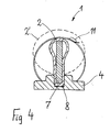
- the water aerator 1 can be biased via a line 5 Air can be supplied. Inflates under the influence of compressed air the hose 2 becomes a substantially cylindrical Body on which in Fig. 4 by a dashed line 2 ' is shown. The slits open and the air can emerge into the environment. The slots are only on the lateral areas of the hose 2 arranged during the top and bottom area of the hose free of slits is.
- the hose can be of great length, possibly several meters exhibit.
- a stiffening Element 7 arranged which is a flat, substantially has rectangular cross section and thus the shape of a Latte, a sword or a stiff band and that made of a solid but somewhat flexible material, e.g. B. Plastic.
- the stiffening element 7 extends over the entire length of the hose 2.
- Hoses 2 can have several elements 7 in a row be arranged. The element 7 is seen in cross section stand upright and is placed together with the hose 1 held by clamping in grooves 8 of the bracket 4 (Fig. 4).
- the pipe socket 6 For the connection between the feed line 5 and the hose 2 serves a pipe socket 6, which in one end of the hose 2nd is inserted. The opposite end, not shown the hose 2 is sealed airtight.
- the pipe socket 6 consists of a tube made of metal or plastic.
- the Diameter of the pipe socket 6 is significantly smaller than that Diameter of the hose 2. In one embodiment the invention, the diameter of the hose was 75 mm and the diameter of the pipe socket 65 mm.
- the hose 2 is with attached to the end of the pipe socket 6, between which Hose 2 and pipe socket 6, however, a ring 10 as Spacer is inserted.
- the pipe socket 6, the ring 10 and the hose 2 are arranged concentrically to one another.
- the end of the hose 2 is by means of a clamp 11 Clamp held on the ring 10. If the clamping force of the Clamp 11 is not sufficient, the entire connection to seal, especially between the pipe socket 6 and Ring 10 sealant arranged or an adhesive, welding or other connection may be provided.
- a relatively long and over a large part of its length cylindrical section 12 of the pipe socket 6 is located inside the hose 2 and is through the ring 10 after limited outside.
- Section 12 has openings 13 provided, via which the air from the supply line 5 in the Hose 2 can get. Due to the great length of the Section 12 can have many openings 13 and thus one large overall cross-section for overflowing the air be provided.
- the one surrounding section 12 Longitudinal section of the hose 2 has no slits to to avoid direct overflow of air.
- the flat section 9 of the pipe socket 6 is vertical arranged. Its internal dimensions correspond approximately to that outer dimensions of the sword or stiffening Element 7. The flat section 9 is thus a smooth transition to sword 7 created.
- the sword 7 and the pipe socket 6 are so together connected that the sword 7 with its at the front end in the flattened section 9 of the pipe socket 6 extends into it.
- the sword 7 and the pipe socket 6 are with the screw 15 connected.
- a connection of the sword 7 with the pipe socket 6 can also be done by gluing, riveting, using a pen or similar are made.
- the sword 7 can as stiffening element can also be used a rod 16, such as is shown in dashed lines in Fig. 2. Not from the staff 16 filled area of the flattened section 9 is in used in this case for the supply of air.
- hose 2 is shown in the form he will take approximately in operation. If at rest the Decreases air pressure, the hose 2 by the pressure of the surrounding water flat against the sword or stiffening Element 7 pressed, as shown in Fig. 4 by the solid Line is shown. The hose 2 also puts on the pipe socket 6, due to the smooth transitions sharp kinks and high strains can be avoided. In this Context, it should be noted that it is on the ring 10, as can be seen in particular in FIG. 3, to a kink of the hose, but it is too small to Impairment, and further because the hose 2 is not slotted in this area anyway, none Sealing problems caused.
Landscapes
- Chemical & Material Sciences (AREA)
- Chemical Kinetics & Catalysis (AREA)
- Rigid Pipes And Flexible Pipes (AREA)
Abstract
Description
- Fig. 1
- einen Wasserbelüfter in schematischer Darstellung,
- Fig. 2
- einen Längsschnitt durch einen Abschnitt einer erfindungsgemäß Vorrichtung (Sicht von der Seite),
- Fig. 3
- die Vorrichtung gemäß Fig. 2 im Längsschnitt in gegenüber Fig. 2 um 90° um die Längsachse gedrehter Darstellung und (Sicht von oben, Darstellung des Rohrstutzens im Schnitt)
- Fig. 4
- einen Querschnitt entlang der Linie IV - IV aus Fig. 2.
Claims (10)
- Vorrichtung zum Belüften von Wasser mit einem biegsamen Schlauch aus Gummi oder einem gummiähnlichen Werkstoff, der im Wasser angeordnet werden kann und dessen Wandung eine Perforation, feine Schlitze, Durchbrechungen oder dgl. aufweist, über die die Luft in das Wasser austreten kann, wobei in ein Ende des Schlauches ein Rohrstutzen eingeführt ist, über den dem Schlauch Luft zugeführt werden kann, dadurch gekennzeichnet, dass das dem Inneren des Schlauches (2) zugewandte Ende (9) des Rohrstutzens (6) flächenhaft ausgebildet ist und in Richtung der Längsachse des Schlauches (2) verläuft, und dass die Wandungen des Rohrstutzens (6) Durchbrechungen (13) zum Durchtritt der Luft aufweisen.
- Vorrichtung nach Anspruch 1, dadurch gekennzeichnet, dass der Rohrstutzen (6) aus einem Rohr besteht, dessen Ende (9) abgeflacht ist.
- Vorrichtung nach Anspruch 1, dadurch gekennzeichnet, dass der Außendurchmesser des Rohrstutzens (6) geringer ist als der Innendurchmesser des Schlauches (2), und dass der Schlauch (2) außen an einem Ring (10) befestigt ist, der den Rohrstutzen (6) umschließt.
- Vorrichtung nach Anspruch 3, dadurch gekennzeichnet, dass der Innendurchmesser des Schlauches größer ist als der Außendurchmesser des Rohrendes.
- Vorrichtung nach Anspruch 3, dadurch gekennzeichnet, dass der Schlauch durch eine Rohrschelle gegen den Ring gepresst wird.
- Vorrichtung nach Anspruch 1, dadurch gekennzeichnet, dass das flache Ende (9) des Rohrstutzens (6) senkrecht angeordnet ist.
- Vorrichtung nach Anspruch 1, dadurch gekennzeichnet, dass in dem Schlauch (6) ein versteifendes Element (7) angeordnet ist, das in Richtung der Längsachse (14) des Schlauches (2) verläuft und das einen flachen Querschnitt aufweist, wobei das versteifende Element (7) und das flache Ende (9) des Rohrstutzens (6) in einer Ebene und zueinander fluchtend angeordnet sind.
- Vorrichtung nach Anspruch 7, dadurch gekennzeichnet, dass das flachen Ende (9) des Rohrstutzens (6) zur Aufnahme des versteifenden Elementes (7, 16) verformt ist.
- Vorrichtung nach Anspruch 7, dadurch gekennzeichnet, dass das versteifende Element (7, 16) in den Rohrstutzen (6) hineinragt.
- Vorrichtung nach Anspruch 8, dadurch gekennzeichnet, dass das versteifende Element (7, 16) mit dem Rohrstutzen durch Schrauben (15) oder in sonstiger Weise verbunden ist.
Applications Claiming Priority (2)
| Application Number | Priority Date | Filing Date | Title |
|---|---|---|---|
| DE10223805A DE10223805A1 (de) | 2002-05-28 | 2002-05-28 | Vorrichtung zum Belüften von Wasser |
| DE10223805 | 2002-05-28 |
Publications (2)
| Publication Number | Publication Date |
|---|---|
| EP1366807A2 true EP1366807A2 (de) | 2003-12-03 |
| EP1366807A3 EP1366807A3 (de) | 2004-01-07 |
Family
ID=29414238
Family Applications (1)
| Application Number | Title | Priority Date | Filing Date |
|---|---|---|---|
| EP03011960A Withdrawn EP1366807A3 (de) | 2002-05-28 | 2003-05-27 | Vorrichtung zum Belüften von Wasser |
Country Status (3)
| Country | Link |
|---|---|
| US (1) | US6880815B2 (de) |
| EP (1) | EP1366807A3 (de) |
| DE (1) | DE10223805A1 (de) |
Families Citing this family (19)
| Publication number | Priority date | Publication date | Assignee | Title |
|---|---|---|---|---|
| USRE43350E1 (en) | 1995-05-05 | 2012-05-08 | Think Village-Kerfoot, Llc | Microporous diffusion apparatus |
| US5855775A (en) | 1995-05-05 | 1999-01-05 | Kerfoot; William B. | Microporous diffusion apparatus |
| US6436285B1 (en) | 1999-12-22 | 2002-08-20 | William B. Kerfoot | Laminated microporous diffuser |
| US8557110B2 (en) | 2000-07-06 | 2013-10-15 | Thinkvillage-Kerfoot, Llc | Groundwater and subsurface remediation |
| US6582611B1 (en) | 2000-07-06 | 2003-06-24 | William B. Kerfoot | Groundwater and subsurface remediation |
| US7666316B2 (en) | 2004-07-20 | 2010-02-23 | Thinkvillage-Kerfoot, Llc | Permanganate-coated ozone for groundwater and soil treatment with in-situ oxidation |
| US8302939B2 (en) | 2003-02-12 | 2012-11-06 | Thinkvillage-Kerfoot, Llc | Soil and water remediation system and method |
| US7442313B2 (en) | 2003-08-27 | 2008-10-28 | Thinkvillage-Kerfoot, Llc | Environmental remediation method and system |
| US6913251B2 (en) | 2003-02-12 | 2005-07-05 | William B. Kerfoot | Deep well sparging |
| US7401767B2 (en) | 2003-12-24 | 2008-07-22 | Kerfoot William B | Directional microporous diffuser and directional sparging |
| US7621696B2 (en) | 2006-07-12 | 2009-11-24 | Thinkvillage-Kerfoot, Llc | Directional microporous diffuser and directional sparging |
| US7651611B2 (en) | 2006-07-12 | 2010-01-26 | Thinkvillage-Kerfoot, Llc | Directional microporous diffuser and directional sparging |
| US8771507B2 (en) | 2003-12-24 | 2014-07-08 | Thinkvillage-Kerfoot, Llc | Directional microporous diffuser and directional sparging |
| US7569140B2 (en) | 2005-11-10 | 2009-08-04 | Thinkvillage-Kerfoot, Llc | Directional spargewell system |
| DE102004036678A1 (de) * | 2004-07-28 | 2006-03-23 | Gummi-Jäger GmbH | Vorrichtung zum Belüften von Wasser |
| DE102010002959A1 (de) * | 2010-03-17 | 2011-09-22 | Invent Umwelt-Und Verfahrenstechnik Ag | Vorrichtung zum Begasen einer in einem Behandlungsbecken aufgenommenen Suspension |
| US9694401B2 (en) | 2013-03-04 | 2017-07-04 | Kerfoot Technologies, Inc. | Method and apparatus for treating perfluoroalkyl compounds |
| CN106966517A (zh) * | 2017-05-22 | 2017-07-21 | 北京得世达环保科技有限公司 | 一种用于充氧曝气的tpu薄壁软管及开孔方式 |
| CN113710268B (zh) * | 2019-03-29 | 2025-07-22 | 国立研究开发法人科学技术振兴机构 | 药物递送组合物 |
Family Cites Families (33)
| Publication number | Priority date | Publication date | Assignee | Title |
|---|---|---|---|---|
| US2415048A (en) * | 1943-04-19 | 1947-01-28 | Sharp William | Equipment for treating sewage |
| US2502187A (en) * | 1947-01-09 | 1950-03-28 | Cardox Corp | Diffuser apparatus for treating liquids with a gaseous medium |
| US2978234A (en) * | 1951-01-16 | 1961-04-04 | Fmc Corp | Diffuser tube |
| US2815943A (en) * | 1951-01-16 | 1957-12-10 | Chicago Pump Co | Diffuser tube |
| US2769760A (en) * | 1953-09-11 | 1956-11-06 | Pure Oil Co | Production of sweet naphthas from hydrocarbon mixtures by hydrofining the hydrocarbon mixture followed by contacting the hydrocarbon product with a composition containing cobalt and molybdenum |
| US2781310A (en) * | 1956-02-06 | 1957-02-12 | Gerson L Ram | Sewage treatment apparatus and method |
| DE1071054B (de) * | 1957-10-02 | 1959-12-17 | The Distillers Company Limited, Epsomi, Surrey (Großbritannien) | Verteilervorrichtung zur Dispersion von äsen in Flüssigkeiten |
| US3219520A (en) * | 1960-10-21 | 1965-11-23 | Hawley Products Co | Paper making apparatus and aerating device with electrical cleaning means |
| US3080124A (en) * | 1960-10-24 | 1963-03-05 | William G Rathmann | Soaker |
| US3206178A (en) * | 1960-11-16 | 1965-09-14 | Fmc Corp | Diffuser tube |
| NL276740A (de) * | 1961-04-06 | |||
| BE625074A (de) * | 1961-11-24 | |||
| US3186644A (en) * | 1963-02-06 | 1965-06-01 | Amcodyne Corp | Diffuser head |
| US3315895A (en) * | 1965-02-05 | 1967-04-25 | Fmc Corp | Diffuser tube |
| NL6602260A (de) * | 1965-02-23 | 1966-08-24 | ||
| US3413307A (en) * | 1965-05-10 | 1968-11-26 | Exxon Research Engineering Co | Desulfurization process |
| US3490752A (en) * | 1966-09-02 | 1970-01-20 | Martin Danjes | Aeration device for sewage plants with biological purification |
| US3432154A (en) * | 1967-11-29 | 1969-03-11 | Martin Hermann Danjes | Sewage water aeration device |
| DE1784398B1 (de) * | 1968-08-03 | 1970-12-10 | Danjes Dipl Ing Martin | Einrichtung zum feinblasigen Belueften von Abwasser |
| US3551328A (en) * | 1968-11-26 | 1970-12-29 | Texaco Inc | Desulfurization of a heavy hydrocarbon fraction |
| US3603509A (en) * | 1970-02-24 | 1971-09-07 | Fmc Corp | Gas dispersing apparatus |
| US3880965A (en) * | 1972-11-24 | 1975-04-29 | Charles G Dudis | Apparatus for aerating a liquid |
| US3841997A (en) * | 1973-04-02 | 1974-10-15 | A Mcgee | Dual aeration and filtration system with recycling |
| DE2513547C3 (de) * | 1975-03-26 | 1978-06-08 | August Dr.-Ing. 3000 Hannover Schreiber | Einrichtung zum intermittierenden Belüften von Abwasser |
| US4118447A (en) * | 1977-06-20 | 1978-10-03 | Xodar Corporation | Aerator containing a ballast charge |
| US4243616A (en) * | 1979-02-15 | 1981-01-06 | Ronald Wyss | Air diffuser |
| US4379750A (en) * | 1981-09-04 | 1983-04-12 | Tigg Corporation | Fluid-solids contact device and improved fluid distributor |
| DE3639473C2 (de) * | 1986-11-18 | 1996-07-11 | Jaeger Arnold | Vorrichtung zum Begasen einer Flüssigkeit |
| DE3700038C2 (de) * | 1987-01-02 | 1998-02-05 | Jaeger Arnold | Zum Belüften von Wasser dienende Vorrichtung |
| US4960546B1 (en) * | 1989-04-19 | 1996-04-09 | Environmental Dynamics Inc | Diffuser mounting arrangement for waste water aeration systems |
| US5032325A (en) * | 1989-11-02 | 1991-07-16 | Environmental Dynamics, Inc. | Plastic coarse bubble diffuser for waste water aeration systems |
| DE10055785A1 (de) * | 2000-11-10 | 2002-06-06 | Gummi Jaeger Kg Gmbh & Cie | Vorrichtung zum Belüften von Wasser |
| DE10203780A1 (de) * | 2002-01-30 | 2003-09-04 | Gummi Jaeger Kg Gmbh & Cie | Vorrichtung zum Belüften von Wasser |
-
2002
- 2002-05-28 DE DE10223805A patent/DE10223805A1/de not_active Withdrawn
-
2003
- 2003-05-27 EP EP03011960A patent/EP1366807A3/de not_active Withdrawn
- 2003-05-28 US US10/446,255 patent/US6880815B2/en not_active Expired - Fee Related
Also Published As
| Publication number | Publication date |
|---|---|
| DE10223805A1 (de) | 2003-12-11 |
| EP1366807A3 (de) | 2004-01-07 |
| US20030222359A1 (en) | 2003-12-04 |
| US6880815B2 (en) | 2005-04-19 |
Similar Documents
| Publication | Publication Date | Title |
|---|---|---|
| EP1366807A2 (de) | Vorrichtung zum Belüften von Wasser | |
| DE2318914C3 (de) | ||
| DE2513547A1 (de) | Einrichtung zum belueften von abwasser | |
| EP1214968A2 (de) | Vorrichtung zum Belüften von Wasser | |
| DE4001201C1 (de) | ||
| DE1229333B (de) | Rueckentragbares Spruehgeraet fuer die Schaedlingsbekaempfung | |
| DE102012005472A1 (de) | Vorrichtung zum Belüften von Wasser, insbesondere Abwasser | |
| DE2201845A1 (de) | Spannvorrichtung fuer an Tragkonstruktionen zu befestigende Abdeckbahn,insbesondere Kunststoffolienbahn | |
| DE10203780A1 (de) | Vorrichtung zum Belüften von Wasser | |
| DE9114013U1 (de) | Vorrichtung zum Begasen von Flüssigkeiten | |
| EP1302235A1 (de) | Halterung für ein Belüftungssystem | |
| DE19621116C2 (de) | Boden-Verteiler zur Beaufschlagung elastischer Schläuche mit Gas | |
| EP0839710A2 (de) | Zusatzeinrichtung für aufblasbare Rettungsflösse | |
| DE3731998A1 (de) | Vorrichtung zur wasserbelueftung | |
| DE10305203A1 (de) | Vorrichtung zum Belüften von Wasser | |
| EP1136448B1 (de) | Vorrichtung zum Belüften von Wasser | |
| DE19540945A1 (de) | Flächenbelüfter mit Hebevorrichtung | |
| DE102008029273B4 (de) | Vorrichtung zum Begasen einer Flüssigkeit, insbesondere zum Belüften von Abwasser, sowie Klärbecken | |
| DE102018129749B3 (de) | Belüftungssystem zum Belüften einer Flüssigkeit, insbesondere Abwasser, und Flüssigkeitsbehälter | |
| DE8426854U1 (de) | Vorrichtung zur Belüftung von Abwasser oder dgl. Medien in Belüftungsbecken | |
| DE102005011527A1 (de) | Vorrichtung zum Belüften von Wasser | |
| AT403684B (de) | Verfahren zum einbringen von hohlraumschutz sowie autokarosserie mit hohlräumen | |
| EP1293483A1 (de) | Abwasserreinigungsanlage mit Belüftungseinrichtung sowie Belüftungselement hierfür | |
| DE1528645C3 (de) | Einrichtung zur Herstellung der Druckstutzenflanschverbindung fur ein Tauchpumpenaggregat | |
| DE102009037760A1 (de) | Kupplungselement zum Anschluss eines Belüftungskörpers einer Gewässer-Belüftungseinrichtung |
Legal Events
| Date | Code | Title | Description |
|---|---|---|---|
| PUAI | Public reference made under article 153(3) epc to a published international application that has entered the european phase |
Free format text: ORIGINAL CODE: 0009012 |
|
| PUAL | Search report despatched |
Free format text: ORIGINAL CODE: 0009013 |
|
| AK | Designated contracting states |
Kind code of ref document: A2 Designated state(s): AT BE BG CH CY CZ DE DK EE ES FI FR GB GR HU IE IT LI LU MC NL PT RO SE SI SK TR |
|
| AX | Request for extension of the european patent |
Extension state: AL LT LV MK |
|
| AK | Designated contracting states |
Kind code of ref document: A3 Designated state(s): AT BE BG CH CY CZ DE DK EE ES FI FR GB GR HU IE IT LI LU MC NL PT RO SE SI SK TR |
|
| AX | Request for extension of the european patent |
Extension state: AL LT LV MK |
|
| 17P | Request for examination filed |
Effective date: 20040705 |
|
| AKX | Designation fees paid |
Designated state(s): AT BE BG CH CY CZ DE DK EE ES FI FR GB GR HU IE IT LI LU MC NL PT RO SE SI SK TR |
|
| STAA | Information on the status of an ep patent application or granted ep patent |
Free format text: STATUS: THE APPLICATION IS DEEMED TO BE WITHDRAWN |
|
| 18D | Application deemed to be withdrawn |
Effective date: 20051201 |