EP1366807A2 - Apparatus for the aeration of water - Google Patents
Apparatus for the aeration of water Download PDFInfo
- Publication number
- EP1366807A2 EP1366807A2 EP03011960A EP03011960A EP1366807A2 EP 1366807 A2 EP1366807 A2 EP 1366807A2 EP 03011960 A EP03011960 A EP 03011960A EP 03011960 A EP03011960 A EP 03011960A EP 1366807 A2 EP1366807 A2 EP 1366807A2
- Authority
- EP
- European Patent Office
- Prior art keywords
- hose
- pipe socket
- air
- water
- pipe
- Prior art date
- Legal status (The legal status is an assumption and is not a legal conclusion. Google has not performed a legal analysis and makes no representation as to the accuracy of the status listed.)
- Withdrawn
Links
- XLYOFNOQVPJJNP-UHFFFAOYSA-N water Substances O XLYOFNOQVPJJNP-UHFFFAOYSA-N 0.000 title claims abstract description 26
- 238000005273 aeration Methods 0.000 title 1
- 239000000463 material Substances 0.000 claims abstract description 5
- 238000005276 aerator Methods 0.000 description 9
- 230000007704 transition Effects 0.000 description 6
- 239000007788 liquid Substances 0.000 description 5
- 239000004033 plastic Substances 0.000 description 4
- 229920003023 plastic Polymers 0.000 description 4
- 238000009423 ventilation Methods 0.000 description 4
- 238000004026 adhesive bonding Methods 0.000 description 2
- 230000006735 deficit Effects 0.000 description 2
- 239000011152 fibreglass Substances 0.000 description 2
- 239000002184 metal Substances 0.000 description 2
- 239000007787 solid Substances 0.000 description 2
- 125000006850 spacer group Chemical group 0.000 description 2
- 239000000853 adhesive Substances 0.000 description 1
- 230000001070 adhesive effect Effects 0.000 description 1
- QVGXLLKOCUKJST-UHFFFAOYSA-N atomic oxygen Chemical compound [O] QVGXLLKOCUKJST-UHFFFAOYSA-N 0.000 description 1
- 235000015115 caffè latte Nutrition 0.000 description 1
- 239000000969 carrier Substances 0.000 description 1
- 230000006835 compression Effects 0.000 description 1
- 238000007906 compression Methods 0.000 description 1
- 238000010276 construction Methods 0.000 description 1
- 230000007423 decrease Effects 0.000 description 1
- 239000013013 elastic material Substances 0.000 description 1
- 238000003958 fumigation Methods 0.000 description 1
- 239000007789 gas Substances 0.000 description 1
- 230000001788 irregular Effects 0.000 description 1
- 239000008239 natural water Substances 0.000 description 1
- 239000001301 oxygen Substances 0.000 description 1
- 229910052760 oxygen Inorganic materials 0.000 description 1
- 230000000149 penetrating effect Effects 0.000 description 1
- 239000000565 sealant Substances 0.000 description 1
- 238000007789 sealing Methods 0.000 description 1
- 238000013022 venting Methods 0.000 description 1
- 238000003466 welding Methods 0.000 description 1
Images

Classifications
-
- B—PERFORMING OPERATIONS; TRANSPORTING
- B01—PHYSICAL OR CHEMICAL PROCESSES OR APPARATUS IN GENERAL
- B01F—MIXING, e.g. DISSOLVING, EMULSIFYING OR DISPERSING
- B01F23/00—Mixing according to the phases to be mixed, e.g. dispersing or emulsifying
- B01F23/20—Mixing gases with liquids
- B01F23/23—Mixing gases with liquids by introducing gases into liquid media, e.g. for producing aerated liquids
- B01F23/231—Mixing gases with liquids by introducing gases into liquid media, e.g. for producing aerated liquids by bubbling
- B01F23/23105—Arrangement or manipulation of the gas bubbling devices
- B01F23/2312—Diffusers
- B01F23/23124—Diffusers consisting of flexible porous or perforated material, e.g. fabric
- B01F23/231241—Diffusers consisting of flexible porous or perforated material, e.g. fabric the outlets being in the form of perforations
- B01F23/231242—Diffusers consisting of flexible porous or perforated material, e.g. fabric the outlets being in the form of perforations in the form of slits or cut-out openings
-
- B—PERFORMING OPERATIONS; TRANSPORTING
- B01—PHYSICAL OR CHEMICAL PROCESSES OR APPARATUS IN GENERAL
- B01F—MIXING, e.g. DISSOLVING, EMULSIFYING OR DISPERSING
- B01F2215/00—Auxiliary or complementary information in relation with mixing
- B01F2215/04—Technical information in relation with mixing
- B01F2215/0413—Numerical information
- B01F2215/0418—Geometrical information
- B01F2215/0431—Numerical size values, e.g. diameter of a hole or conduit, area, volume, length, width, or ratios thereof
-
- B—PERFORMING OPERATIONS; TRANSPORTING
- B01—PHYSICAL OR CHEMICAL PROCESSES OR APPARATUS IN GENERAL
- B01F—MIXING, e.g. DISSOLVING, EMULSIFYING OR DISPERSING
- B01F23/00—Mixing according to the phases to be mixed, e.g. dispersing or emulsifying
- B01F23/20—Mixing gases with liquids
- B01F23/23—Mixing gases with liquids by introducing gases into liquid media, e.g. for producing aerated liquids
- B01F23/231—Mixing gases with liquids by introducing gases into liquid media, e.g. for producing aerated liquids by bubbling
- B01F23/23105—Arrangement or manipulation of the gas bubbling devices
- B01F23/2312—Diffusers
- B01F23/23124—Diffusers consisting of flexible porous or perforated material, e.g. fabric
- B01F23/231244—Dissolving, hollow fiber membranes
-
- B—PERFORMING OPERATIONS; TRANSPORTING
- B01—PHYSICAL OR CHEMICAL PROCESSES OR APPARATUS IN GENERAL
- B01F—MIXING, e.g. DISSOLVING, EMULSIFYING OR DISPERSING
- B01F23/00—Mixing according to the phases to be mixed, e.g. dispersing or emulsifying
- B01F23/20—Mixing gases with liquids
- B01F23/23—Mixing gases with liquids by introducing gases into liquid media, e.g. for producing aerated liquids
- B01F23/231—Mixing gases with liquids by introducing gases into liquid media, e.g. for producing aerated liquids by bubbling
- B01F23/23105—Arrangement or manipulation of the gas bubbling devices
- B01F23/2312—Diffusers
- B01F23/23125—Diffusers characterised by the way in which they are assembled or mounted; Fabricating the parts of the diffusers
Definitions
- the invention relates to a device for venting Water with a flexible rubber hose or a rubber-like material that can be placed in water and the wall is perforated, fine slits, Breakthroughs or the like. Via which the air in the Water can leak, entering one end of the hose Pipe socket is inserted through which the hose is air can be supplied.
- the hose In water aerators of a known, frequently used type the hose is arranged on a support tube (e.g. DE 37 00 038 C2).
- the hose has a slightly larger one Diameter than the support tube. The air gets between that Support tube and the hose passed. It inflates the hose and lifts it off the support tube. The open up Slits in the hose and the air escapes into the water. When the device is at rest and not the hose is supported by compressed air Pipe off and the slots are closed again.
- stiffening element can be on the outside of the hose attached, e.g. a profile.
- the stiffening element can but also be arranged within the hose, being Circumference, in contrast to the support tube described above, however, is significantly smaller than the circumference of the hose.
- Such an element can e.g. B. be a round bar.
- a stiffening element is particularly advantageous a solid but flexible material in the form of a sword or a slat with a flat rectangular cross section proven that is arranged within the hose that the longer sides of the cross section are vertical. This Element offers high rigidity against deformation Buoyancy forces, but leaves horizontal movements and Deformation of the hose as a result of water flows, without a sharp kink. With these Ventilation elements, the hose is at rest when it is not fed with compressed air due to the pressure of the surrounding water pressed flat together and thereby against penetrating water completed.
- the invention has for its object in a Device of the type mentioned the connection for the Air supply in one for the construction without support tube to form a suitable shape.
- the pipe socket can easily be made from a pipe be produced, the end of which is plastically deformed is pressed flat. Has proven to be particularly advantageous proven to only carry out the plastic deformation to the extent that a slot to accommodate the stiffening element remains. A slat-like can then be inserted into this slot Support body are introduced. Become support body and Screwed pipe sockets together or z. B. by gluing otherwise firmly connected, a connection is obtained of the elements, which are twisting or tilting of the elements to each other prevented, but at least made difficult.
- the rod is inserted into the vertical slot of the bottom Pipe socket introduced.
- the rod can also be connected to the nozzle screwed, glued or in any other way firmly to the Connecting piece.
- the rod is preferably made of Metal or glass fiber reinforced plastic (GRP).
- Diameter of the pipe socket less than the diameter of the Hose, and the hose is by means of an as Spacer serving ring attached to the pipe socket.
- This embodiment is advantageous because it is flat pressed end of the pipe socket has a width that is larger is than the diameter of the pipe.
- the hose can be without Deformation will be carried across this broad end and fixed well and securely at a distance from the wide end become.
- This embodiment is also advantageous because because the pipe socket with a longer section in it Be inserted. Because the end of the pipe socket due to its flat training essentially is closed, the air is transported via the Openings in the wall of the pipe socket. For longer Section of the pipe socket can be many Openings can be arranged, making a good one low flow resistance air supply to the Ventilation element is made possible.
- the water aerator 1 consists essentially of a Hose 2, which is arranged in the liquid to be gassed can be.
- the hose 2 consists of an elastic Material, especially rubber or a rubber-like Plastic. It is provided with fine slits for a section of its surface is indicated at 3.
- Brackets 4 are used to attach the water aerator 1 on Bottom of a basin that contains the liquid to be fumigated picks up, or on carriers or the like, which in the liquid can be introduced, or also for the attachment of Float when the water aerator 1 floats freely in the water should be arranged.
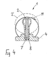
- the water aerator 1 can be biased via a line 5 Air can be supplied. Inflates under the influence of compressed air the hose 2 becomes a substantially cylindrical Body on which in Fig. 4 by a dashed line 2 ' is shown. The slits open and the air can emerge into the environment. The slots are only on the lateral areas of the hose 2 arranged during the top and bottom area of the hose free of slits is.
- the hose can be of great length, possibly several meters exhibit.
- a stiffening Element 7 arranged which is a flat, substantially has rectangular cross section and thus the shape of a Latte, a sword or a stiff band and that made of a solid but somewhat flexible material, e.g. B. Plastic.
- the stiffening element 7 extends over the entire length of the hose 2.
- Hoses 2 can have several elements 7 in a row be arranged. The element 7 is seen in cross section stand upright and is placed together with the hose 1 held by clamping in grooves 8 of the bracket 4 (Fig. 4).
- the pipe socket 6 For the connection between the feed line 5 and the hose 2 serves a pipe socket 6, which in one end of the hose 2nd is inserted. The opposite end, not shown the hose 2 is sealed airtight.
- the pipe socket 6 consists of a tube made of metal or plastic.
- the Diameter of the pipe socket 6 is significantly smaller than that Diameter of the hose 2. In one embodiment the invention, the diameter of the hose was 75 mm and the diameter of the pipe socket 65 mm.
- the hose 2 is with attached to the end of the pipe socket 6, between which Hose 2 and pipe socket 6, however, a ring 10 as Spacer is inserted.
- the pipe socket 6, the ring 10 and the hose 2 are arranged concentrically to one another.
- the end of the hose 2 is by means of a clamp 11 Clamp held on the ring 10. If the clamping force of the Clamp 11 is not sufficient, the entire connection to seal, especially between the pipe socket 6 and Ring 10 sealant arranged or an adhesive, welding or other connection may be provided.
- a relatively long and over a large part of its length cylindrical section 12 of the pipe socket 6 is located inside the hose 2 and is through the ring 10 after limited outside.
- Section 12 has openings 13 provided, via which the air from the supply line 5 in the Hose 2 can get. Due to the great length of the Section 12 can have many openings 13 and thus one large overall cross-section for overflowing the air be provided.
- the one surrounding section 12 Longitudinal section of the hose 2 has no slits to to avoid direct overflow of air.
- the flat section 9 of the pipe socket 6 is vertical arranged. Its internal dimensions correspond approximately to that outer dimensions of the sword or stiffening Element 7. The flat section 9 is thus a smooth transition to sword 7 created.
- the sword 7 and the pipe socket 6 are so together connected that the sword 7 with its at the front end in the flattened section 9 of the pipe socket 6 extends into it.
- the sword 7 and the pipe socket 6 are with the screw 15 connected.
- a connection of the sword 7 with the pipe socket 6 can also be done by gluing, riveting, using a pen or similar are made.
- the sword 7 can as stiffening element can also be used a rod 16, such as is shown in dashed lines in Fig. 2. Not from the staff 16 filled area of the flattened section 9 is in used in this case for the supply of air.
- hose 2 is shown in the form he will take approximately in operation. If at rest the Decreases air pressure, the hose 2 by the pressure of the surrounding water flat against the sword or stiffening Element 7 pressed, as shown in Fig. 4 by the solid Line is shown. The hose 2 also puts on the pipe socket 6, due to the smooth transitions sharp kinks and high strains can be avoided. In this Context, it should be noted that it is on the ring 10, as can be seen in particular in FIG. 3, to a kink of the hose, but it is too small to Impairment, and further because the hose 2 is not slotted in this area anyway, none Sealing problems caused.
Landscapes
- Chemical & Material Sciences (AREA)
- Chemical Kinetics & Catalysis (AREA)
- Rigid Pipes And Flexible Pipes (AREA)
Abstract
Description
Die Erfindung betrifft eine Vorrichtung zum Belüften von Wasser mit einem biegsamen Schlauch aus Gummi oder einem gummiähnlichen Werkstoff, der im Wasser angeordnet werden kann und dessen Wandung eine Perforation, feine Schlitze, Durchbrechungen oder dgl. aufweist, über die die Luft in das Wasser austreten kann, wobei in ein Ende des Schlauches ein Rohrstutzen eingeführt ist, über den dem Schlauch Luft zugeführt werden kann.The invention relates to a device for venting Water with a flexible rubber hose or a rubber-like material that can be placed in water and the wall is perforated, fine slits, Breakthroughs or the like. Via which the air in the Water can leak, entering one end of the hose Pipe socket is inserted through which the hose is air can be supplied.
Bei Wasserbelüftern eines bekannten, häufig verwendeten Typs ist der Schlauch auf einem Stützrohr angeordnet (z.B. DE 37 00 038 C2). Der Schlauch hat einen geringfügig größeren Durchmesser als das Stützrohr. Die Luft wird zwischen das Stützrohr und den Schlauch geleitet. Sie bläht den Schlauch auf und hebt ihn vom Stützrohr ab. Dabei öffnen sich die Schlitze im Schlauch, und die Luft tritt in das Wasser aus. Wenn sich die Vorrichtung im Ruhezustand befindet und nicht mit Druckluft beschickt wird, stützt sich der Schlauch auf dem Rohr ab und die Schlitze sind wieder geschlossen.In water aerators of a known, frequently used type the hose is arranged on a support tube (e.g. DE 37 00 038 C2). The hose has a slightly larger one Diameter than the support tube. The air gets between that Support tube and the hose passed. It inflates the hose and lifts it off the support tube. The open up Slits in the hose and the air escapes into the water. When the device is at rest and not the hose is supported by compressed air Pipe off and the slots are closed again.
Um den Aufbau der Wasserbelüfter noch deutlich zu vereinfachen, aber auch, um flexibler beim Einbau der Wasserbelüfter in der zu begasenden Umgebung sein zu können - diese kann beispielsweise ein Klärbecken, aber auch ein offenes, natürliches Gewässer mit unregelmäßigen, "weichen" Begrenzungen sein - und schließlich auch, um den Strömungswiderstand der Luft innerhalb der Belüfter zu verringern, sind Vorrichtungen der eingangs genannten Art vorgeschlagen worden, bei denen auf ein Stützrohr verzichtet wird (zum Zeitpunkt dieser Anmeldung noch nicht veröffentlichten Patentanmeldung DE 102 03 780.9). Auch bei diesen Vorrichtungen wird dem Schlauch ein parallel verlaufendes, versteifendes Element zugeordnet, durch das eine zu starke Verformung, insb. ein Abknicken des Schlauches in Folge von Wasserströmungen und Auftrieb und eine damit verbundene Beeinträchtigung der Begasung verhindert wird. Ein derartiges versteifendes Element kann außen am Schlauch befestigt sein, z.B. ein Profil. Das versteifende Element kann aber auch innerhalb des Schlauches angeordnet sein, wobei sein Umfang, im Gegensatz zu dem oben beschriebenen Stützrohr, jedoch deutlich geringer ist als der Umfang des Schlauches. Ein derartiges Element kann z. B. ein Rundstab sein. Als besonders vorteilhaft hat sich ein versteifendes Element aus einem festen, aber flexiblen Werkstoff in Form eines Schwertes oder einer Latte mit einem flach rechteckigen Querschnitt erwiesen, das so innerhalb des Schlauches angeordnet ist, dass die längeren Seiten des Querschnittes senkrecht stehen. Dieses Element bietet hohe Steifigkeit gegen Verformungen durch Auftriebskräften, lässt aber waagerechte Bewegungen und Verformungen des Schlauches in Folge von Wasserströmungen zu, ohne dass es zu einem scharfen Abknicken kommt. Bei diesen Belüftungselementen wird der Schlauch im Ruhezustand, wenn er nicht mit Druckluft beschickt wird, durch den Druck des umgebenden Wassers flach zusammen gepresst und dadurch gegen eindringendes Wasser abgeschlossen.To the structure of the water aerator still significantly simplify, but also to be more flexible when installing the Water aerators must be in the area to be fumigated can - this can be, for example, a clarifier, but also a open, natural water with irregular, "soft" Be limitations - and finally, around that Flow resistance of the air inside the aerator increases reduce, are devices of the type mentioned have been proposed in which there is no support tube not (at the time of this registration published patent application DE 102 03 780.9). Also at These devices become parallel to the hose associated, stiffening element, by the one excessive deformation, especially kinking of the hose in Sequence of water currents and buoyancy and one with it associated impairment of fumigation is prevented. On such stiffening element can be on the outside of the hose attached, e.g. a profile. The stiffening element can but also be arranged within the hose, being Circumference, in contrast to the support tube described above, however, is significantly smaller than the circumference of the hose. Such an element can e.g. B. be a round bar. As A stiffening element is particularly advantageous a solid but flexible material in the form of a sword or a slat with a flat rectangular cross section proven that is arranged within the hose that the longer sides of the cross section are vertical. This Element offers high rigidity against deformation Buoyancy forces, but leaves horizontal movements and Deformation of the hose as a result of water flows, without a sharp kink. With these Ventilation elements, the hose is at rest when it is not fed with compressed air due to the pressure of the surrounding water pressed flat together and thereby against penetrating water completed.
Bei den oben beschriebenen Vorrichtung mit Stützrohr erfolgt die Luftzufuhr über einen Rohrstutzen, der in das offene Ende des Schlauches eingesetzt ist, wobei der Rohrstutzen und das Stützrohr den gleiche Durchmesser aufweisen und der Schlauch mittels einer Schelle auf dem Stutzen festgeklemmt ist (DE 37 00 038 C2). Eine entsprechende Bauweise würde bei einer Vorrichtung ohne Stützrohr wegen des flache Zusammenpressens des Schlauches im Ruhezustand zu Problemen führen. Es würde sich ein Übergangsbereich zwischen dem von dem Rohrstutzen gebildeten zylindrischen Bereich und dem flachen Bereich herausbilden, in dem der Schlauch stellenweise hohen mechanischen Belastungen ausgesetzt ist, insb. durch Abknicken an den Kanten des Rohrstutzens. Ferner fehlt in diesem Übergangsbereich eine Abdichtung im Ruhezustand, so dass er frei von Schlitzen bleiben muss und somit für die Belüftung nicht nutzbar ist.In the device described above with a support tube the air supply through a pipe socket that goes into the open end of the hose is used, the pipe socket and the Support tube have the same diameter and the hose is clamped on the nozzle by means of a clamp (DE 37 00 038 C2). A corresponding design would be used for a Device without support tube due to the flat compression lead to problems when the hose is idle. It would there is a transition area between that of the pipe socket formed cylindrical area and the flat area form in which the hose is high in places is exposed to mechanical loads, especially by kinking on the edges of the pipe socket. Furthermore, this is missing Transition area a seal at rest so that he must remain free of slits and therefore for ventilation is not usable.
Der Erfindung liegt die Aufgabe zugrunde, bei einer Vorrichtung der eingangs genannten Art den Anschluss für die Luftversorgung in einer für die Bauweise ohne Stützrohr geeigneten Form auszubilden.The invention has for its object in a Device of the type mentioned the connection for the Air supply in one for the construction without support tube to form a suitable shape.
Diese Aufgabe wird erfindungsgemäß dadurch gelöst, dass das dem Inneren des Schlauches zugewandte Ende des Rohrstutzens flächenhaft ausgebildet ist und in Richtung der Längsachse des Schlauches verläuft, und dass die Wandungen des Rohrstutzens Durchbrechungen zum Durchtritt der Luft aufweisen.This object is achieved in that the end of the pipe socket facing the inside of the hose is flat and in the direction of the longitudinal axis of the Hose runs, and that the walls of the pipe socket Have openings for air to pass through.
Somit ist der Übergang von der zylindrischen zu flachen Form am Rohrstutzen selbst ausgebildet. Im Ruhezustand legen sich die Wandungen des Schlauches teils auf den Rohrstutzen, teils auf den Stützkörper und/oder gegen gegenüberliegende Wandungsteile, ohne dass es zu einem scharfen Abknicken an einer Kante kommt. Vorzugsweise wird bei der erfindungsgemäßen Vorrichtung der Rohrstutzen so angeordnet, dass sein flaches Ende senkrecht steht. In besonders vorteilhafter Weise wird der Rohrstutzen zusammen mit einem im Schlauch angeordneten flachen, lattenartigen Stützkörper verwendet, da durch diesen Stützkörper die Form des Schlauches im drucklosen Zustand vorgegeben wird, so dass unerwünschte Verwerfungen im Übergangsbereich vermieden werden können.So the transition from cylindrical to flat shape trained on the pipe socket itself. Lie down in the idle state the walls of the hose partly on the pipe socket, partly on the support body and / or opposite Wall parts without causing a sharp kink an edge is coming. Preferably in the invention Device of the pipe socket arranged so that its flat End is vertical. In a particularly advantageous manner the pipe socket together with one arranged in the hose flat, slat-like support body used because of this Support body the shape of the hose when depressurized is specified so that undesirable faults in the Transition area can be avoided.
Der Rohrstutzen kann in einfacher Weise aus einem Rohr hergestellt werden, dessen Ende unter plastischer Verformung flach gedrückt wird. Als besonders vorteilhaft hat sich erwiesen, die plastische Verformung nur soweit durchzuführen, dass ein Schlitz zur Aufnahme des versteifenden Elementes verbleibt. In diesen Schlitz kann dann ein lattenartiger Stützkörper eingeführt werden. Werden Stützkörper und Rohrstutzen miteinander verschraubt oder z. B. durch Verkleben in sonstiger Weise fest verbunden, erhält man eine Verbindung der Elemente, welche ein Verdrehen oder Verkanten der Elemente zueinander verhindert, zumindest aber erschwert.The pipe socket can easily be made from a pipe be produced, the end of which is plastically deformed is pressed flat. Has proven to be particularly advantageous proven to only carry out the plastic deformation to the extent that a slot to accommodate the stiffening element remains. A slat-like can then be inserted into this slot Support body are introduced. Become support body and Screwed pipe sockets together or z. B. by gluing otherwise firmly connected, a connection is obtained of the elements, which are twisting or tilting of the elements to each other prevented, but at least made difficult.
Auch die Verwendung eines runden Stabes statt des vorerwähnten lattenartigen Stützkörpers als versteifendes Element hat sich als eine vorteilhafte Ausführung der Erfindung erwiesen. Der Stab wird unten in den senkrecht stehenden Schlitz des Rohrstutzens eingeführt. Auch der Stab kann mit dem Stutzen verschraubt, verklebt oder in sonstiger Weise fest mit dem Stutzen verbunden werden. Der Stab besteht vorzugsweise aus Metall oder glasfaserverstärktem Kunststoff (GfK). Also the use of a round bar instead of the aforementioned slat-like support body as a stiffening element has proven as an advantageous embodiment of the invention. The The rod is inserted into the vertical slot of the bottom Pipe socket introduced. The rod can also be connected to the nozzle screwed, glued or in any other way firmly to the Connecting piece. The rod is preferably made of Metal or glass fiber reinforced plastic (GRP).
Nach einer vorteilhaften Ausführungsform der Erfindung ist der Durchmesser des Rohrstutzens geringer als der Durchmesser des Schlauches, und der Schlauch ist mittels eines als Abstandhalter dienenden Ringes auf dem Rohrstutzen befestigt. Diese Ausführungsform ist deswegen vorteilhaft, weil das flach gepresste Ende des Rohrstutzens eine Breite hat, die größer ist als der Durchmesser des Rohres. Der Schlauch kann ohne Deformation über dieses breite Ende hinweg geführt werden und im Abstand von dem breiten Ende gut und sicher befestigt werden. Diese Ausführungsform ist zudem deswegen vorteilhaft, weil der Rohrstutzen mit einem längeren Abschnitt in das Schlauchende eingeschoben werden. Da das Ende des Rohrstutzens aufgrund seiner flachen Ausbildung im wesentlichen verschlossen ist, erfolgt der Lufttransport über die Durchbrechungen in der Wandung des Rohrstutzens. Auf längeren Abschnitt des Rohrstutzens können entsprechend viele Durchbrechungen angeordnet sein, wodurch eine gute, einen geringen Strömungswiderstand aufweisende Luftzufuhr zum Belüftungselement ermöglicht wird.According to an advantageous embodiment of the invention Diameter of the pipe socket less than the diameter of the Hose, and the hose is by means of an as Spacer serving ring attached to the pipe socket. This embodiment is advantageous because it is flat pressed end of the pipe socket has a width that is larger is than the diameter of the pipe. The hose can be without Deformation will be carried across this broad end and fixed well and securely at a distance from the wide end become. This embodiment is also advantageous because because the pipe socket with a longer section in it Be inserted. Because the end of the pipe socket due to its flat training essentially is closed, the air is transported via the Openings in the wall of the pipe socket. For longer Section of the pipe socket can be many Openings can be arranged, making a good one low flow resistance air supply to the Ventilation element is made possible.
Es liegt im Rahmen der Erfindung, mehrere Belüftungselemente in Verbindung miteinander, z. B. parallel zueinander anzuordnen. Es versteht sich ferner, dass die Vorrichtung, auch wenn vorgehend stets von Luft und Wasser die Rede war, auch zum Transport von anderen Gasen, z. B. von Sauerstoff, geeignet ist, und dass mit ihr nicht nur Wasser, sondern auch andere flüssige oder im wesentlichen flüssige Medien begast werden können.It is within the scope of the invention, several ventilation elements in connection with each other, e.g. B. parallel to each other to arrange. It is further understood that the device even if there was always talk of air and water, also for the transport of other gases, e.g. B. of oxygen, is suitable, and that with it not only water, but also fumigates other liquid or essentially liquid media can be.
Weitere Einzelheiten der Erfindung werden anhand der Zeichnung erläutert, in der ein Ausführungsbeispiel der Erfindung dargestellt ist. Es zeigen:
- Fig. 1
- einen Wasserbelüfter in schematischer Darstellung,
- Fig. 2
- einen Längsschnitt durch einen Abschnitt einer erfindungsgemäß Vorrichtung (Sicht von der Seite),
- Fig. 3
- die Vorrichtung gemäß Fig. 2 im Längsschnitt in gegenüber Fig. 2 um 90° um die Längsachse gedrehter Darstellung und (Sicht von oben, Darstellung des Rohrstutzens im Schnitt)
- Fig. 4
- einen Querschnitt entlang der Linie IV - IV aus Fig. 2.
- Fig. 1
- a water aerator in a schematic representation,
- Fig. 2
- 2 shows a longitudinal section through a section of a device according to the invention (view from the side),
- Fig. 3
- 2 in longitudinal section in comparison with FIG. 2 rotated by 90 ° about the longitudinal axis and (view from above, representation of the pipe socket in section)
- Fig. 4
- 3 shows a cross section along the line IV-IV from FIG. 2.
Der Wasserbelüfter 1 besteht im wesentlichen aus einem
Schlauch 2, der in der zu begasenden Flüssigkeit angeordnet
werden kann. Der Schlauch 2 besteht aus einem elastischen
Werkstoff, insb. aus Gummi oder einem gummiähnlichen
Kunststoff. Er ist mit feinen Schlitzen versehen ist, die für
einen Ausschnitt seiner Oberfläche bei 3 angedeutet sind.
Halterungen 4 dienen zur Befestigung des Wasserbelüfters 1 am
Boden eines Beckens, das die zu begasende Flüssigkeit
aufnimmt, oder an Trägern oder dgl., die in die Flüssigkeit
eingebracht werden können, oder auch zur Anbringung von
Schwimmern, wenn der Wasserbelüfter 1 im Wasser frei schwebend
angeordnet sein soll.The
Über eine Leitung 5 kann dem Wasserbelüfter 1 vorgespannte
Luft zugeführt werden. Unter dem Einfluss der Druckluft bläht
sich der Schlauch 2 zu einem im wesentlichen zylindrischen
Körper auf, der in Fig. 4 durch eine gestrichelte Linie 2'
dargestellt ist. Die Schlitze öffnen sich, und die Luft kann
in die Umgebung austreten. Die Schlitze sind dabei nur an den
seitlichen Bereichen des Schlauches 2 angeordnet, während der
oberste und unterste Bereich des Schlauches von Schlitzen frei
ist.The
Der Schlauch kann eine große Länge, evtl. von mehreren Metern
aufweisen. Im Inneren des Schlauches 2 ist ein versteifendes
Element 7 angeordnet, das einen flachen, im wesentlichen
rechteckigen Querschnitt aufweist und somit die Form einer
Latte, eines Schwertes oder eines steifen Bandes hat und das
aus einem festen, aber etwas flexiblem Material, z. B.
Kunststoff, besteht. Das versteifende Element 7 erstreckt sich
über die gesamte Länge des Schlauches 2. Bei sehr langen
Schläuchen 2 können mehrere Elemente 7 hintereinander
angeordnet sein. Das Element 7 ist im Querschnitt gesehen
aufrecht stehen angeordnet und wird zusammen mit dem Schlauch
1 durch Klemmung in Nuten 8 der Halterung 4 gehalten (Fig. 4).The hose can be of great length, possibly several meters
exhibit. Inside the
Zur Verbindung zwischen der Zuleitung 5 und dem Schlauch 2
dient ein Rohrstutzen 6, der in ein Ende des Schlauches 2
eingeschoben ist. Das nicht dargestellte entgegengesetzte Ende
des Schlauches 2 ist luftdicht verschlossen. Der Rohrstutzen 6
besteht aus einem Rohr aus Metall oder Kunststoff. Der
Durchmesser des Rohrstutzens 6 ist deutlich geringer als der
Durchmesser des Schlauches 2. Bei einem Ausführungsbeispiel
der Erfindung betrug der Durchmesser des Schlauches 75 mm und
der Durchmesser des Rohrstutzens 65 mm. Der Schlauch 2 ist mit
seinem Ende auf dem Rohrstutzen 6 befestigt, wozu zwischen
Schlauch 2 und Rohrstutzen 6 jedoch noch ein Ring 10 als
Abstandhalter eingefügt ist. Der Rohrstutzen 6, der Ring 10
und der Schlauch 2 sind konzentrisch zueinander angeordnet.
Das Ende des Schlauches 2 ist mittels einer Schelle 11 durch
Klemmung auf dem Ring 10 gehalten. Falls die Klemmkraft der
Schelle 11 nicht ausreicht, die gesamte Verbindung
abzudichten, kann insb. zwischen dem Rohrstutzen 6 und dem
Ring 10 Dichtmittel angeordnet oder eine Klebe-, Schweiß- oder
andere Verbindung vorgesehen sein. For the connection between the feed line 5 and the
Ein relativ langer und über einen großen Teil seiner Länge
zylindrischer Abschnitt 12 des Rohrstutzens 6 befindet sich
innerhalb des Schlauches 2 und wird durch den Ring 10 nach
außen begrenzt. Der Abschnitt 12 ist mit Durchbrechungen 13
versehen, über die die Luft von der Zuleitung 5 in den
Schlauch 2 gelangen kann. Aufgrund der großen Länge des
Abschnittes 12 können viele Durchbrechungen 13 und damit ein
großer Gesamtquerschnitt für das Überströmen der Luft
vorgesehen werden. Der den Abschnitt 12 umgebende
Längenabschnitt des Schlauches 2 weist keine Schlitze auf, um
ein direktes Überströmen der Luft zu vermeiden.A relatively long and over a large part of its length
Der flache Abschnitt 9 des Rohrstutzen 6 ist senkrecht
angeordnet. Seine inneren Abmessungen entsprechen in etwa den
äußeren Abmessungen des Schwertes bzw. des versteifenden
Elementes 7. Durch den flachen Abschnitt 9 wird somit ein
fließender Übergang zum Schwert 7 geschaffen.The
Das Schwert 7 und der Rohrstutzen 6 sind derart miteinander
verbunden, dass das Schwert 7 mit seinem am vorderen Ende in
den abgeflachten Abschnitt 9 des Rohrstutzens 6 hinein reicht.
Das Schwert 7 und der Rohrstutzen 6 sind mit der Schraube 15
verbunden. Eine Verbindung des Schwertes 7 mit dem Rohrstutzen
6 kann auch durch Verkleben, Vernieten, mit einem Stift oder
ähnlichem hergestellt werden. Statt des Schwertes 7 kann als
versteifendes Element auch ein Stab 16 verwendet werden, wie
in Fig. 2 gestrichelt dargestellt ist. Die nicht von dem Stab
16 ausgefüllte Fläche des abgeflachten Abschnittes 9 wird in
diesem Fall für die Zufuhr der Luft genutzt.The
In Fig. 3 ist der Schlauch 2 in der Form dargestellt, die er
im Betrieb in etwa einnehmen wird. Wenn im Ruhezustand der
Luftdruck nachlässt, wird der Schlauch 2 durch den Druck des
umgebenden Wassers flach gegen das Schwert bzw. versteifende
Element 7 gedrückt, wie dies in Fig. 4 durch die durchgezogene
Linie dargestellt ist. Der Schlauch 2 legt sich ebenfalls an
den Rohrstutzen 6 an, wobei aufgrund der sanften Übergänge
scharfe Knicke und hohe Dehnungen vermieden werden. In diesem
Zusammenhang sei noch darauf hingewiesen, dass es an dem Ring
10, wie insb. Fig. 3 erkennen lässt, zwar zu einem Abknicken
des Schlauches kommen kann, das jedoch zu gering ist, um zu
Beeinträchtigungen zu führen, und das ferner, da der Schlauch
2 in diesem Bereich ohnehin nicht geschlitzt ist, keine
Abdichtungsprobleme verursacht.In Fig. 3, the
Claims (10)
Applications Claiming Priority (2)
| Application Number | Priority Date | Filing Date | Title |
|---|---|---|---|
| DE10223805A DE10223805A1 (en) | 2002-05-28 | 2002-05-28 | Device for aerating water |
| DE10223805 | 2002-05-28 |
Publications (2)
| Publication Number | Publication Date |
|---|---|
| EP1366807A2 true EP1366807A2 (en) | 2003-12-03 |
| EP1366807A3 EP1366807A3 (en) | 2004-01-07 |
Family
ID=29414238
Family Applications (1)
| Application Number | Title | Priority Date | Filing Date |
|---|---|---|---|
| EP03011960A Withdrawn EP1366807A3 (en) | 2002-05-28 | 2003-05-27 | Apparatus for the aeration of water |
Country Status (3)
| Country | Link |
|---|---|
| US (1) | US6880815B2 (en) |
| EP (1) | EP1366807A3 (en) |
| DE (1) | DE10223805A1 (en) |
Families Citing this family (16)
| Publication number | Priority date | Publication date | Assignee | Title |
|---|---|---|---|---|
| US5855775A (en) | 1995-05-05 | 1999-01-05 | Kerfoot; William B. | Microporous diffusion apparatus |
| USRE43350E1 (en) | 1995-05-05 | 2012-05-08 | Think Village-Kerfoot, Llc | Microporous diffusion apparatus |
| US6582611B1 (en) | 2000-07-06 | 2003-06-24 | William B. Kerfoot | Groundwater and subsurface remediation |
| US8557110B2 (en) | 2000-07-06 | 2013-10-15 | Thinkvillage-Kerfoot, Llc | Groundwater and subsurface remediation |
| US7442313B2 (en) | 2003-08-27 | 2008-10-28 | Thinkvillage-Kerfoot, Llc | Environmental remediation method and system |
| US6913251B2 (en) | 2003-02-12 | 2005-07-05 | William B. Kerfoot | Deep well sparging |
| US8302939B2 (en) | 2003-02-12 | 2012-11-06 | Thinkvillage-Kerfoot, Llc | Soil and water remediation system and method |
| US7666316B2 (en) | 2004-07-20 | 2010-02-23 | Thinkvillage-Kerfoot, Llc | Permanganate-coated ozone for groundwater and soil treatment with in-situ oxidation |
| US7401767B2 (en) | 2003-12-24 | 2008-07-22 | Kerfoot William B | Directional microporous diffuser and directional sparging |
| US7651611B2 (en) | 2006-07-12 | 2010-01-26 | Thinkvillage-Kerfoot, Llc | Directional microporous diffuser and directional sparging |
| US8771507B2 (en) | 2003-12-24 | 2014-07-08 | Thinkvillage-Kerfoot, Llc | Directional microporous diffuser and directional sparging |
| DE102004036678A1 (en) * | 2004-07-28 | 2006-03-23 | Gummi-Jäger GmbH | Device for aerating water |
| DE102010002959A1 (en) * | 2010-03-17 | 2011-09-22 | Invent Umwelt-Und Verfahrenstechnik Ag | Apparatus for gassing a suspension received in a treatment tank |
| US9694401B2 (en) | 2013-03-04 | 2017-07-04 | Kerfoot Technologies, Inc. | Method and apparatus for treating perfluoroalkyl compounds |
| CN106966517A (en) * | 2017-05-22 | 2017-07-21 | 北京得世达环保科技有限公司 | A kind of TPU thin walled hoses and perforate mode for oxygenic aeration |
| US20220249386A1 (en) * | 2019-03-29 | 2022-08-11 | Japan Science And Technology Agency | Drug delivery composition |
Citations (2)
| Publication number | Priority date | Publication date | Assignee | Title |
|---|---|---|---|---|
| DE3700038A1 (en) * | 1987-01-02 | 1988-07-14 | Jaeger Arnold | Apparatus serving for the aeration of water |
| CA2361476A1 (en) * | 2000-11-10 | 2002-05-10 | Andreas Jager | Apparatus for aerating water |
Family Cites Families (31)
| Publication number | Priority date | Publication date | Assignee | Title |
|---|---|---|---|---|
| US2415048A (en) * | 1943-04-19 | 1947-01-28 | Sharp William | Equipment for treating sewage |
| US2502187A (en) * | 1947-01-09 | 1950-03-28 | Cardox Corp | Diffuser apparatus for treating liquids with a gaseous medium |
| US2978234A (en) * | 1951-01-16 | 1961-04-04 | Fmc Corp | Diffuser tube |
| US2815943A (en) * | 1951-01-16 | 1957-12-10 | Chicago Pump Co | Diffuser tube |
| US2769760A (en) * | 1953-09-11 | 1956-11-06 | Pure Oil Co | Production of sweet naphthas from hydrocarbon mixtures by hydrofining the hydrocarbon mixture followed by contacting the hydrocarbon product with a composition containing cobalt and molybdenum |
| US2781310A (en) * | 1956-02-06 | 1957-02-12 | Gerson L Ram | Sewage treatment apparatus and method |
| DE1071054B (en) * | 1957-10-02 | 1959-12-17 | The Distillers Company Limited, Epsomi, Surrey (Großbritannien) | Distribution device for the dispersion of grains in liquids |
| US3219520A (en) * | 1960-10-21 | 1965-11-23 | Hawley Products Co | Paper making apparatus and aerating device with electrical cleaning means |
| US3080124A (en) * | 1960-10-24 | 1963-03-05 | William G Rathmann | Soaker |
| US3206178A (en) * | 1960-11-16 | 1965-09-14 | Fmc Corp | Diffuser tube |
| NL276740A (en) * | 1961-04-06 | |||
| BE625074A (en) * | 1961-11-24 | |||
| US3186644A (en) * | 1963-02-06 | 1965-06-01 | Amcodyne Corp | Diffuser head |
| US3315895A (en) * | 1965-02-05 | 1967-04-25 | Fmc Corp | Diffuser tube |
| NL6602260A (en) * | 1965-02-23 | 1966-08-24 | ||
| US3413307A (en) * | 1965-05-10 | 1968-11-26 | Exxon Research Engineering Co | Desulfurization process |
| US3490752A (en) * | 1966-09-02 | 1970-01-20 | Martin Danjes | Aeration device for sewage plants with biological purification |
| US3432154A (en) * | 1967-11-29 | 1969-03-11 | Martin Hermann Danjes | Sewage water aeration device |
| DE1784398B1 (en) * | 1968-08-03 | 1970-12-10 | Danjes Dipl Ing Martin | Device for fine-bubble aeration of waste water |
| US3551328A (en) * | 1968-11-26 | 1970-12-29 | Texaco Inc | Desulfurization of a heavy hydrocarbon fraction |
| US3603509A (en) * | 1970-02-24 | 1971-09-07 | Fmc Corp | Gas dispersing apparatus |
| US3880965A (en) * | 1972-11-24 | 1975-04-29 | Charles G Dudis | Apparatus for aerating a liquid |
| US3841997A (en) * | 1973-04-02 | 1974-10-15 | A Mcgee | Dual aeration and filtration system with recycling |
| DE2513547C3 (en) * | 1975-03-26 | 1978-06-08 | August Dr.-Ing. 3000 Hannover Schreiber | Device for intermittent aeration of waste water |
| US4118447A (en) * | 1977-06-20 | 1978-10-03 | Xodar Corporation | Aerator containing a ballast charge |
| US4243616A (en) * | 1979-02-15 | 1981-01-06 | Ronald Wyss | Air diffuser |
| US4379750A (en) * | 1981-09-04 | 1983-04-12 | Tigg Corporation | Fluid-solids contact device and improved fluid distributor |
| DE3639473C2 (en) * | 1986-11-18 | 1996-07-11 | Jaeger Arnold | Device for gassing a liquid |
| US4960546B1 (en) * | 1989-04-19 | 1996-04-09 | Environmental Dynamics Inc | Diffuser mounting arrangement for waste water aeration systems |
| US5032325A (en) * | 1989-11-02 | 1991-07-16 | Environmental Dynamics, Inc. | Plastic coarse bubble diffuser for waste water aeration systems |
| DE10203780A1 (en) * | 2002-01-30 | 2003-09-04 | Gummi Jaeger Kg Gmbh & Cie | Perforated hose, e.g. for aeration of sewage, comprises a stiffening element along its longitudinal axis at an unperforated wall section, for the delivery of large volumes of air without floating |
-
2002
- 2002-05-28 DE DE10223805A patent/DE10223805A1/en not_active Withdrawn
-
2003
- 2003-05-27 EP EP03011960A patent/EP1366807A3/en not_active Withdrawn
- 2003-05-28 US US10/446,255 patent/US6880815B2/en not_active Expired - Fee Related
Patent Citations (2)
| Publication number | Priority date | Publication date | Assignee | Title |
|---|---|---|---|---|
| DE3700038A1 (en) * | 1987-01-02 | 1988-07-14 | Jaeger Arnold | Apparatus serving for the aeration of water |
| CA2361476A1 (en) * | 2000-11-10 | 2002-05-10 | Andreas Jager | Apparatus for aerating water |
Also Published As
| Publication number | Publication date |
|---|---|
| DE10223805A1 (en) | 2003-12-11 |
| EP1366807A3 (en) | 2004-01-07 |
| US20030222359A1 (en) | 2003-12-04 |
| US6880815B2 (en) | 2005-04-19 |
Similar Documents
| Publication | Publication Date | Title |
|---|---|---|
| EP1366807A2 (en) | Apparatus for the aeration of water | |
| DE2513547A1 (en) | DEVICE FOR VENTILATING WASTE WATER | |
| EP0309474B1 (en) | Process and device for large surface-area fine-bubble gasification of liquids | |
| DE1784398B1 (en) | Device for fine-bubble aeration of waste water | |
| EP1214968A2 (en) | Device for aerating water | |
| WO1993004770A2 (en) | Aerator for a liquid-filled basin | |
| DE4001201C1 (en) | ||
| DE102013106845A1 (en) | Device for distributing gases in liquids | |
| DE102012005472A1 (en) | Device useful for aerating water, preferably waste water in container comprises tube provided with perforations for exit of air bubbles, radially projecting bridge, first and second fastening devices connected to container base and port | |
| DE2201845A1 (en) | Clamping device for cover sheet to be attached to supporting structures, especially plastic film sheet | |
| DE10203780A1 (en) | Perforated hose, e.g. for aeration of sewage, comprises a stiffening element along its longitudinal axis at an unperforated wall section, for the delivery of large volumes of air without floating | |
| EP1302235A1 (en) | Support for a aeration system | |
| DE9114013U1 (en) | Device for gassing liquids | |
| EP0839710A2 (en) | Supplementary equipment for inflatable liferafts | |
| DE3731998A1 (en) | Apparatus for water aeration | |
| EP0808804B1 (en) | Distributor for introducing gas into elastic tubes | |
| DE10305203A1 (en) | Device for aerating water | |
| DE3218460A1 (en) | Pipe for aerating water | |
| DE102018129749B3 (en) | Ventilation system for aerating a liquid, in particular waste water, and liquid container | |
| EP0806400A1 (en) | Bent aerator | |
| DE102005011527A1 (en) | water oxygenation assembly has a rubber bag hose with numerous tiny slits and is clamped or secured to the floor of a water basin | |
| DE19540945A1 (en) | Surface aerator for settlement tanks comprising horizontal composite of hollow sections | |
| DE8426854U1 (en) | Device for aeration of waste water or the like. Media in aeration basins | |
| EP1293483A1 (en) | Wastewater treatment plant with aeration device | |
| AT403684B (en) | METHOD FOR INSERTING CAVITY PROTECTION AND CAR BODY WITH CAVES |
Legal Events
| Date | Code | Title | Description |
|---|---|---|---|
| PUAI | Public reference made under article 153(3) epc to a published international application that has entered the european phase |
Free format text: ORIGINAL CODE: 0009012 |
|
| PUAL | Search report despatched |
Free format text: ORIGINAL CODE: 0009013 |
|
| AK | Designated contracting states |
Kind code of ref document: A2 Designated state(s): AT BE BG CH CY CZ DE DK EE ES FI FR GB GR HU IE IT LI LU MC NL PT RO SE SI SK TR |
|
| AX | Request for extension of the european patent |
Extension state: AL LT LV MK |
|
| AK | Designated contracting states |
Kind code of ref document: A3 Designated state(s): AT BE BG CH CY CZ DE DK EE ES FI FR GB GR HU IE IT LI LU MC NL PT RO SE SI SK TR |
|
| AX | Request for extension of the european patent |
Extension state: AL LT LV MK |
|
| 17P | Request for examination filed |
Effective date: 20040705 |
|
| AKX | Designation fees paid |
Designated state(s): AT BE BG CH CY CZ DE DK EE ES FI FR GB GR HU IE IT LI LU MC NL PT RO SE SI SK TR |
|
| STAA | Information on the status of an ep patent application or granted ep patent |
Free format text: STATUS: THE APPLICATION IS DEEMED TO BE WITHDRAWN |
|
| 18D | Application deemed to be withdrawn |
Effective date: 20051201 |