EP1365355B1 - Procédé et dispositif pour l'accentuation des contours - Google Patents
Procédé et dispositif pour l'accentuation des contours Download PDFInfo
- Publication number
- EP1365355B1 EP1365355B1 EP03077304.8A EP03077304A EP1365355B1 EP 1365355 B1 EP1365355 B1 EP 1365355B1 EP 03077304 A EP03077304 A EP 03077304A EP 1365355 B1 EP1365355 B1 EP 1365355B1
- Authority
- EP
- European Patent Office
- Prior art keywords
- edge
- image
- level
- edge enhancement
- pixels
- Prior art date
- Legal status (The legal status is an assumption and is not a legal conclusion. Google has not performed a legal analysis and makes no representation as to the accuracy of the status listed.)
- Expired - Lifetime
Links
- 238000012545 processing Methods 0.000 title claims description 74
- 238000000034 method Methods 0.000 title description 9
- 239000011159 matrix material Substances 0.000 claims description 13
- 238000012937 correction Methods 0.000 claims description 2
- 238000003672 processing method Methods 0.000 claims description 2
- 235000019557 luminance Nutrition 0.000 description 21
- 230000002093 peripheral effect Effects 0.000 description 7
- 239000013598 vector Substances 0.000 description 6
- 238000010276 construction Methods 0.000 description 4
- 238000010586 diagram Methods 0.000 description 4
- 230000010354 integration Effects 0.000 description 4
- 238000012935 Averaging Methods 0.000 description 3
- 238000007792 addition Methods 0.000 description 3
- 230000000007 visual effect Effects 0.000 description 3
- 238000006243 chemical reaction Methods 0.000 description 2
- 238000004891 communication Methods 0.000 description 2
- 230000007423 decrease Effects 0.000 description 1
- 230000001419 dependent effect Effects 0.000 description 1
- 230000000694 effects Effects 0.000 description 1
- 230000002708 enhancing effect Effects 0.000 description 1
- 238000006467 substitution reaction Methods 0.000 description 1
Images


Classifications
-
- G—PHYSICS
- G06—COMPUTING; CALCULATING OR COUNTING
- G06T—IMAGE DATA PROCESSING OR GENERATION, IN GENERAL
- G06T5/00—Image enhancement or restoration
- G06T5/73—Deblurring; Sharpening
- G06T5/75—Unsharp masking
-
- G—PHYSICS
- G06—COMPUTING; CALCULATING OR COUNTING
- G06T—IMAGE DATA PROCESSING OR GENERATION, IN GENERAL
- G06T7/00—Image analysis
- G06T7/10—Segmentation; Edge detection
- G06T7/12—Edge-based segmentation
-
- G—PHYSICS
- G06—COMPUTING; CALCULATING OR COUNTING
- G06T—IMAGE DATA PROCESSING OR GENERATION, IN GENERAL
- G06T2207/00—Indexing scheme for image analysis or image enhancement
- G06T2207/10—Image acquisition modality
- G06T2207/10016—Video; Image sequence
-
- G—PHYSICS
- G06—COMPUTING; CALCULATING OR COUNTING
- G06T—IMAGE DATA PROCESSING OR GENERATION, IN GENERAL
- G06T2207/00—Indexing scheme for image analysis or image enhancement
- G06T2207/20—Special algorithmic details
- G06T2207/20172—Image enhancement details
- G06T2207/20192—Edge enhancement; Edge preservation
Definitions
- the present invention relates to an edge-enhancement processing apparatus and method for performing edge enhancement processing based on multi-level image data representing an image with pixels in dot matrix, and a medium containing an edge-enhancement processing program.
- image-processing software programs for performing edge enhancement processing to enhance edge portions on image data representing a photograph or the like are known. These programs read image data into a computer, convert the image data at different edge enhancement levels by trial and error. An operator checks the converted result on a display screen by visual observation, thus adjusting it to have appropriately enhanced edge portions.
- Japanese Patent Application Laid-Open No. 6-68252 discloses obtaining high frequency components in edge areas of an image by using a high-frequency band filter, judging the sharpness of the image based on the mean value of the high frequency components and controlling an edge enhancement parameter.
- US 5204919 discloses a method for performing detail enhancement in which, based on the size of an image to be reproduced, a standard observation distance between the image and an observer is computed. A spatial frequency to be intensified is found so that it corresponds to about 12 cpd at the standard observation distance. The size of a pixel area suitable in producing an unsharp signal is set to be inversely proportional to the spatial frequency. Signals for various pixel areas are prepared, and one of these signals which is obtained for the suitable pixel area is selected to be the unsharp signal. An enhanced image signal is produced on the basis of the unsharp signal and a sharp signal.
- an object of the present invention is to provide an edge-enhancement processing apparatus and method capable of judging the sharpness of an image with a simpler method and automatically performing optimum edge enhancement processing. According to a first aspect of the present invention, there is provided an edge enhancement processing apparatus comprising:
- the edge-enhancement element determination unit determines the edge enhancement element
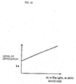
- the unit detects the image size of the image data, and sets the edge enhancement element such that as the image size increases, the enhancement level increases.
- the enhancement level must be raised so that the large image has the same visual effect of equal value as the small one.
- an optimum edge enhancement level can be set by using the image size, corresponding to effect of edge enhancement processing, as a reference for edge-enhancement element determination.
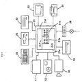
- Fig. 1 is a block diagram showing an image processing system to which an edge-enhancement processing apparatus according to an embodiment of the present invention is applied.
- Fig. 2 is a block diagram showing the hardware construction of the edge-enhancement processing apparatus.
- an image input device 10 outputs image data, representing a photograph or the like with pixels in dot matrix, to an image processor 20.
- the image processor 20 executes image processing to perform edge enhancement processing at a predetermined enhancement level.
- the image processor 20 outputs the edge-enhancement processed image data to an image output device 30.
- the image output device 30 outputs an edge-enhancement processed image represented with pixels in dot matrix.
- the image data outputted from the image processor 20 is corrected image data having improved sharpness by enhancement on unsharp image edges.
- the image processor 20 has an image-data obtaining unit which obtains image data from the image input device 10, a summation processing unit which calculates a change level by each pixel based on a luminance level value and sums up change level, an edge-enhancement element determination unit which determines an edge enhancement element based on the result of summation, and an edge enhancement unit which performs enhancement on respective edge pixels based on the determined edge enhancement element and outputs the edge-enhancement processed image data to the image output device 30.
- the image input device 10 is realized by a scanner 11, a digital still camera 12, a video camera 14 or the like.
- the image processor 20 is realized by a computer system comprising a computer 21, a hard disk 22, a keyboard 23, a CD-ROM drive 24, a floppy disk drive 25, a modem 26 and the like.
- the image output device 30 is realized by a printer 31, a display 32 or the like.
- edge enhancement processing is performed as image processing, the image data preferably represents a natural image such as a photograph.
- the modem 26 is connected to a public communication line, and connected to an external network via the public communication line for downloading software program and data.
- the scanner 11 or the digital still camera 12 as the image input device 10 outputs RGB (red, green and blue) multi-level data as image data.
- the printer 31 as the image output device 30 inputs CMY (cyan, magenta and yellow) multi-level data or CMYK (cyan, magenta, yellow and black) binary data.
- the display 32 inputs RGB multi-level data.
- an operating system 21a operates in the computer main body 21, further, a printer driver 21b for the printer 31 and a display driver 21c for the display 32 are installed in the computer main body 21.
- an image-processing application program 21d executes a predetermined image processing in cooperation with the printer driver 21b and the display driver 21c in accordance with necessity, under the control of the operating system 21a. Accordingly, the computer main body 21 as the image processor 20 inputs RGB multi-level data, performs edge enhancement processing at an optimum enhancement level on the input data, displays the edge-enhancement processed RGB multi-level data on the display 32 via the display driver 21c, and at the same time, converts the data into CMY binary data and print-outputs the converted data by the printer 31 via the printer driver 21b.
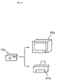
- a computer system is provided between image input device and image output device for edge enhancement processing, however, the computer system is not always necessary, but any system which performs edge enhancement processing on image data can be employed.
- the system may be arranged as shown in Fig. 3 , where an image processing device for edge enhancement processing is incorporated in a digital still camera 12a, and converted image data is displayed on a display 32a or print-outputted by a printer 31a.
- a printer 31b inputs image data via a scanner 11b, a digital still camera 12b, a modem 26b or the like without a computer system, and prints an image based on the input image data.
- edge enhancement processing is automatically performed on the input image data.
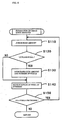
- the edge enhancement processing is made by the image processing program in the computer main body 21 corresponding to the flowchart as shown in Fig. 5 .
- step S100 edge amounts of respective pixels are calculated and summed up for judging the sharpness level of the image
- step S200 an edge enhancement element is determined based on the result of summation
- step S300 edge enhancement processing is performed in accordance with the edge enhancement element.
- step S100 edge amounts are summed up to judge the sharpness level of the image.
- the summation processing is shown in more detail in the flowchart of Fig. 6 .
- each pixels is represented by multi-level RGB luminance data.
- the difference of the luminance data between adjacent pixels is large.
- the difference which is a luminance gradient, is called an edge amount.
- edge amounts are summed up while scanning the respective pixels constituting the image.
- the edge amount of the each pixel is judged.
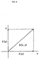
- the vector of a image change level can be calculated by obtaining an X-axis directional component and a Y-axis directional component.
- the pixels are adjacent to each other in a vertical axial direction and a lateral axial direction as shown in Fig. 9 .
- the brightness of these pixels are represented by f(x,y).
- f(x,y) may be R(x,y), G(x,y) and B(x,y) as respective RGB luminances or a total luminance Y(x,y).
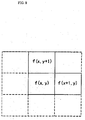
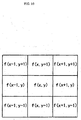
- the edge amount is represented by this
- the central pixel when the central pixel is regarded as a pixel of interest, there are eight adjacent pixels. Accordingly, it maybe arranged such that the differences between the pixel of interest and the respective adjacent pixels are represented by vectors, and the sum of the vectors is judged as the change level of the image. Note that it can be said that the less the number of pixels to be compared is, the less the amount of calculation is. Further, regarding the adjacent pixels arrayed in at least a linear direction, they interact with each other when the position of a pixel of interest moves. Accordingly, the calculation on these pixels may be omitted. To further reduce the calculation amount, the difference of luminance may be calculated only between adjacent pixels arrayed in the lateral direction. The calculation is made by utilizing the luminance, however, if substitute values for the luminance are used in the calculation, including simple calculation, substantially the same results can be obtained.
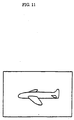
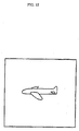
- Figs. 11 and 12 show pictures of airplanes in flight. Apparently, in these figures, the sky portions as the backgrounds of the images do not have a great image change level. However, assuming that the airplanes as the subjects have the same sharpness level, if image sharpness level is respectively obtained by averaging edge amounts of all the pixels, the sharpness level of the image in Fig. 12 , having the airplane of the same sharpness level as that of the airplane in Fig. 11 but including a greater background than that in Fig. 11 , is lower than that of the image in Fig. 11 . Accordingly, averaging is not appropriate in obtaining image sharpness level.
- the mean value of the edge amounts of all the pixels is not obtained, but the mean value of only edge amounts of outline portions is obtained so as to judge how sharp the outline portions is in the image.
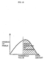
- Fig. 13 shows a histogram in a case where edge amounts are summed up with respect to all the pixels, indicating that only pixels having edge amounts over a threshold value are subjected to the summation. More specifically, at step S120, the edge amount is compared with a predetermined threshold value to determine whether or not the pixel belongs to an outline portion. Only if the pixel belongs to an outline portion, the process proceeds to step S130, in which the edge amount is integrated, and the number of pixels in the outline portions is integrated.
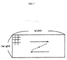
- step S140 To perform the pixel-based judgment on all the pixels, at step S140, the position of pixel of interest is moved as shown in Fig. 7 , and the processing is repeated until it is determined at step S150 that the judgment on all the pixels has been completed.
- edge-enhancement element determination is performed at step S200.
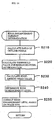
- the edge-enhancement element determination is shown in more detail in the flowchart of Fig. 14 .
- edge_rate edge_pixel / total_pixel
- the image has more edge pixels.
- the sharpness level of the airplane in the image in Fig. 11 and that in Fig. 12 are the same, however, the number of background pixels in the image in Fig. 11 and that in Fig. 12 are different.
- the background image of the greater number of pixels is rather blurred, but it is not necessarily sharp. That is, it is preferable to avoid performing edge enhancement processing on the background pixels.
- Such background includes a gradation portion of blue sky, a skin portion of a portrait and the like.
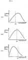
- Figs. 15(a) to 15(c) show the relation between the edge amount distribution and the threshold value ST.
- the total edge amount is large.
- a threshold value ST0 is low.
- a threshold value ST2 is high.
- Fig. 15(b) shows an intermediate threshold value ST1 between those in Figs. 15 (a) and 15(c) . That is, when the number of sharp pixels is small, the threshold value ST is set to a high value, so that more pixels are judged as non-edge pixels in determination of non-edge pixel. This avoids enhancement on noise in a skin portion or the like.
- Eenhance KS ⁇ SLopt ⁇ SL * * 1 / 2
- KS min height width / A
- “min(height,width)” indicates “height” dots or "width” dots as a smaller number of dots.
- “A” is a constant having a value "768". They have been experimentally obtained and may be appropriately changed. Basically, excellent results have been obtained by increasing the enhancement level as the image size becomes greater.
- edge enhancement processing is performed on all the pixels at step S300.
- the edge enhancement processing is shown in more detail in the flowchart of Fig. 17 .
- the pixel of interest is determined in advance, and as shown in Fig. 7 , the position of the pixel of interest is moved to scan all the pixels.
- the above-described threshold value ST and the edge amount of each pixel are compared to determine whether or not the pixel is to be subjected to edge enhancement processing. If the edge amount is greater than the threshold value ST, it is determined that the pixel is to be subjected to edge enhancement processing, and at step S320, edge enhancement processing is performed on the pixel.
- Step S320 is edge enhancement processing calculation.
- "Yunsharp" indicates image data of each pixel which has been unsharp-mask processed.
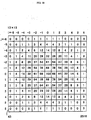
- Figs. 18 to 20 show unsharp masks 40 (41 to 43) of three different sizes.
- Mij indicates a weight coefficient given in a cell of the unsharp mask; and "Y(x,y)", image data of each pixel. Note that “ij” indicates coordinate values in the row and column directions in the different sized unsharp masks 41 to 43.
- the high-pass filtered high frequency component is multiplied by the edge enhancement level Eenhance, and the multiplied result is added to "Y (x, y) " .
- This increases the high frequency component in proportion to the edge enhancement level Eenhance, as a result, the edge is enhanced.
- the edge enhancement level also changes dependent on the size of the unsharp mask.
- the weighting with respect to the peripheral pixels around a pixel of interest is greater, while the weighting gradually decreases toward distant pixels.
- the weighting characteristic as a low-pass filter increases, and the generation of high frequency component can be made more easily in accordance with equation (8).
- the edge enhancement level Eenhance is high, the large unsharp mask 43 is used, while if the edge enhancement level Eenhance is low, the small unsharp mask 41 is used. In case of an intermediate number of pixels, the middle sized unsharp mask 42 is used.
- the unsharp mask 40 has the greatest weight coefficient at its central portion, and gradually-decreasing weighting values toward its ends.
- the variation of the weighting is not necessarily fixedly determined but may be appropriately changed.
- the mask is not necessarily an "unsharp mask", and its size is not limited to those shown in the figures. It may be composed of 6 ⁇ 6 cells or 8 ⁇ 8 cells.
- the unsharp mask 40 is arranged so as to reduce the processing amount.
- the unsharp mask 40 of an appropriate size is employed, calculation is not necessarily required for all the cells.
- the weighting with respect to the outmost peripheral cells is "0" or "1". In case of weighting by "0”, the multiplication by "0" is meaningless, while in case of weighting by "1", very low weighted results are obtained in comparison with the total cell value "632".
- calculation is not performed with respect to all the cells of the 7 ⁇ 7-cell unsharp mask 42, but an unsharp mask 44 having 5 ⁇ 5 cells within a double-line block in the unsharp mask 42 is used.
- the unsharp mask 44 By using the unsharp mask 44, the outmost peripheral portion of the 7 ⁇ 7-cell unsharp mask 42 is omitted.
- the outmost peripheral portion of the 13 ⁇ 13-cell unsharp mask 43 may be omitted.
- edge enhancement is required in so-called image edge portions, the processing is limited to portions where image data greatly changes between adjacent pixels. In consideration of this situation, it may be arranged such that the calculation is performed when there is a large difference of image data between adjacent pixels. This unnecessitates the calculation with an unsharp mask at almost all image data portions which are not image edges, thus greatly reduces processing.
- luminance Y has been described as the luminance of each pixel, for the sake of assistance of understanding, however, each pixel actually has RGB multi-level data, and the luminance Y is converted by simple weighting on the RGB multi-level data as shown in equation (1).
- steps S110 to S150 to sum up edge amounts so as to judge the sharpness level of the image, correspond to the summation process unit; steps S210 to S250, to set a threshold value to determine edge enhancement level and to determine a pixel to be edge-enhanced, correspond to the edge-enhancement element determination unit; and steps S310 to S340, to perform edge enhancement calculation on pixels to be subjected to edge enhancement processing, correspond to the edge enhancement unit.
- the processing by a hardware device and a software program to obtain image data handled in the edge enhancement processing correspond to the image-data obtaining unit.
- edge amounts are summed up is determined based on whether or not each pixel is an outline pixel, however, this determination is used in only one example where summation is performed with respect to pixels having large edge amounts.
- the sharpness level of the entire image may be judged by so-called weighting with attention to pixels having large edge amounts.
- the edge amount is integrated, and the number of pixels is incremented at step S130, however, as shown in Fig. 21 , the summation may be performed with respect to all the pixels such that as the edge amount increases, the weight increases.
- the edge amount is divided by the number of pixels as a result of integration with weighting, thus obtaining a result where pixels having small edge amounts are processed with a low attention level while pixels having large edge amounts are processed with a high attention level.
- the method for actual weighting in this case may be appropriately changed. Further, it may be arranged such that the number of outline pixels are summed up based on whether or not each pixel is outline pixel while adding attention to pixels having large edge amounts.
- the image-processing application program 21d is activated when the operating system 21a is operating in the computer main body 21, to cause the scanner 11 to read the photograph.
- the read image data is read by the application program 21d via the operating system 21a, then a pixel of interest is set, and at step S110, the edge amount is determined based on equations (2) to (4).
- step S140 the above processing is repeated while the position of the pixel of interest is moved, until it is determined at step S150 that the processing on all the pixels has been performed.
- the ratio of the number of outline pixels is calculated at step S210, and the threshold value used for judgment of edge-enhanced pixel is calculated at step S220.
- the mean value of edge amounts of the outline pixels is calculated from the integrated edge amount and the number of pixels, and at step S240, the edge enhancement level Eenhance is calculated from equations (6) and (7), based on the image size according to the image data.
- steps S310 to S340 actual edge enhancement processing is performed on each pixel while the position of the pixel of interest is moved similarly to the above processing.
- one of the unsharp masks 41 to 43 may be selected in accordance with the edge enhancement level Eenhance. Further, the processing speed can be improved by omitting calculation based on various calculation reducing methods.
- the edge-enhanced image data is displayed on the display 32 via the display driver 21c. If the displayed image is excellent, the image is printed by the printer 31 via the printer driver 21b. That is, the printer driver 21b inputs the edge-enhanced RGB multi-level data, performs rasterization corresponding to a print head area of the printer 31 via a predetermined resolution conversion, converts the rasterized RGB data to CMYK data, then, converts the CMYK multi-level data to binary data, and outputs the data to the printer 31.
- the image data of the photograph read via the scanner 11 is automatically subjected to optimum edge enhancement processing, then displayed on the display 32, and print-outputted by the printer 31.
- the computer main body 21 which functions as the nucleus of edge enhancement process ing, generates a vector from the difference value of data between adjacent pixels and obtains an edge amount as a change level at step S110, selects only pixels having large edge amounts and integrates the edge amounts at steps S120 and S130, and obtains the mean value at step S230.
- the computer main body 21 obtains the sharpness level of the image while adding attention to the pixels having large image change levels, then determines the edge enhancement level Eenhance based on the obtained sharpness level of the image.
- the computer main body 21 automatically performs edge enhancement processing at an optimum enhancement level.
Landscapes
- Engineering & Computer Science (AREA)
- Physics & Mathematics (AREA)
- General Physics & Mathematics (AREA)
- Theoretical Computer Science (AREA)
- Computer Vision & Pattern Recognition (AREA)
- Image Processing (AREA)
- Facsimile Image Signal Circuits (AREA)
Claims (2)
- Appareil de traitement d'amélioration de contours comprenant :une unité d'obtention de données d'image qui obtient des données d'image multi-niveaux représentant une image avec des pixels en matrice à points ;une unité d'obtention de niveau d'amélioration de contours qui obtient un niveau d'amélioration de contours sur la base d'une différence entre un niveau de netteté fixé et un niveau de netteté de l'image ;une unité de correction de niveau d'amélioration de contours qui détecte une taille d'image des données d'image, comprenant une hauteur des données d'image dans une direction verticale et une largeur des données d'image dans une direction latérale, et qui corrige le niveau d'amélioration de contours en multipliant le niveau d'amélioration de contours par un coefficient déterminé en fonction du minimum de la hauteur ou de la largeur, de telle sorte que le coefficient augmente avec une augmentation du minimum de la hauteur ou de la largeur ; etune unité d'amélioration de contours qui effectue un traitement d'amélioration de contours pour des pixels de contour respectifs sur la base du niveau d'amélioration de contours corrigé.
- Procédé de traitement d'amélioration de contours pour effectuer un traitement d'amélioration de contours pour des données d'image multi-niveaux représentant une image avec des pixels en matrice à points, comprenant :une étape d'obtention de données d'image multi-niveaux représentant une image avec des pixels en matrice à points ;une étape d'obtention d'un niveau d'amélioration de contours sur la base d'une différence entre un niveau de netteté fixé et un niveau de netteté de l'image ;une étape de détection d'une taille d'image des données d'image, comprenant une hauteur des données d'image dans une direction verticale et une largeur des données d'image dans une direction latérale, et la correction du niveau d'amélioration de contours en multipliant le niveau d'amélioration de contours par un coefficient déterminé en fonction du minimum de la hauteur ou de la largeur, de telle sorte que le coefficient augmente avec une augmentation du minimum de la hauteur ou de la largeur, etune étape de réalisation d'un traitement d'amélioration de contours pour des pixels de contour respectifs sur la base du niveau d'amélioration de contours corrigé.
Applications Claiming Priority (3)
| Application Number | Priority Date | Filing Date | Title |
|---|---|---|---|
| JP14405997 | 1997-06-02 | ||
| JP14405997 | 1997-06-02 | ||
| EP98304240A EP0883086B1 (fr) | 1997-06-02 | 1998-05-28 | Procédé et dispositif pour l'accentuation des contours |
Related Parent Applications (1)
| Application Number | Title | Priority Date | Filing Date |
|---|---|---|---|
| EP98304240A Division EP0883086B1 (fr) | 1997-06-02 | 1998-05-28 | Procédé et dispositif pour l'accentuation des contours |
Publications (3)
| Publication Number | Publication Date |
|---|---|
| EP1365355A2 EP1365355A2 (fr) | 2003-11-26 |
| EP1365355A3 EP1365355A3 (fr) | 2004-08-11 |
| EP1365355B1 true EP1365355B1 (fr) | 2016-03-16 |
Family
ID=15353362
Family Applications (2)
| Application Number | Title | Priority Date | Filing Date |
|---|---|---|---|
| EP03077304.8A Expired - Lifetime EP1365355B1 (fr) | 1997-06-02 | 1998-05-28 | Procédé et dispositif pour l'accentuation des contours |
| EP98304240A Expired - Lifetime EP0883086B1 (fr) | 1997-06-02 | 1998-05-28 | Procédé et dispositif pour l'accentuation des contours |
Family Applications After (1)
| Application Number | Title | Priority Date | Filing Date |
|---|---|---|---|
| EP98304240A Expired - Lifetime EP0883086B1 (fr) | 1997-06-02 | 1998-05-28 | Procédé et dispositif pour l'accentuation des contours |
Country Status (4)
| Country | Link |
|---|---|
| US (1) | US6392759B1 (fr) |
| EP (2) | EP1365355B1 (fr) |
| JP (1) | JP4492704B2 (fr) |
| DE (1) | DE69822923T2 (fr) |
Families Citing this family (26)
| Publication number | Priority date | Publication date | Assignee | Title |
|---|---|---|---|---|
| EP2199973A3 (fr) | 1997-06-09 | 2010-09-08 | Seiko Epson Corporation | Appareil et procédé de traitement d'images, et dispositif et procédé d'évaluation d'images |
| US6774943B1 (en) | 1998-09-01 | 2004-08-10 | Ess Technology, Inc. | Method and apparatus for edge enhancement in digital images |
| EP1079601B1 (fr) * | 1999-03-05 | 2008-06-18 | Seiko Epson Corporation | Correcteur de donnees d'image, procede de correction de donnees d'image, support sur lequel est enregistre le programme de correction de donnees d'image |
| JP3736219B2 (ja) | 1999-08-13 | 2006-01-18 | コニカミノルタビジネステクノロジーズ株式会社 | 画像処理装置及び方法 |
| US6721457B1 (en) * | 1999-08-27 | 2004-04-13 | Hewlett-Packard Development Company, L.P. | Method for enhancing digital images |
| US20020061062A1 (en) * | 2000-11-22 | 2002-05-23 | O'brien Royal | Filtering system and method for digital interactive streams |
| WO2003049031A1 (fr) * | 2001-11-19 | 2003-06-12 | Siemens Aktiengesellschaft | Reduction temporelle du bruit et amplification locale des contrastes |
| US7119854B2 (en) * | 2001-12-28 | 2006-10-10 | Koninklijke Philips Electronics N.V. | Method for deriving an objective sharpness metric |
| JP3863808B2 (ja) * | 2002-05-27 | 2006-12-27 | 三洋電機株式会社 | 輪郭強調回路 |
| JP4228641B2 (ja) * | 2002-09-20 | 2009-02-25 | セイコーエプソン株式会社 | 出力対象画像データ選択 |
| GB0224357D0 (en) * | 2002-10-19 | 2002-11-27 | Eastman Kodak Co | Image processing |
| US7149354B2 (en) * | 2002-12-12 | 2006-12-12 | Intel Corporation | Extraction of a scene structure based on gradient runs analysis |
| JP4258385B2 (ja) * | 2004-01-14 | 2009-04-30 | 株式会社デンソー | 路面反射検出装置 |
| DE102004034532B4 (de) * | 2004-07-16 | 2009-05-28 | Audi Ag | Verfahren zur Kennzeichnung von Bildinformationen in der Darstellung eines mit einer fahrzeugseitigen Bildaufnahmeeinrichtung aufgenommenen Nachtsichtbildes und zugehöriges Nachtsichtsystem |
| KR100647955B1 (ko) * | 2004-12-03 | 2006-11-23 | 엘지전자 주식회사 | 디포커스 현상을 보정하는 영상처리장치 |
| JP4992212B2 (ja) * | 2005-09-06 | 2012-08-08 | ソニー株式会社 | 画像処理装置、画像判定方法及びプログラム |
| JP4637063B2 (ja) * | 2006-07-04 | 2011-02-23 | キヤノン株式会社 | 画像処理装置、画像処理方法およびプログラム |
| JP4677376B2 (ja) * | 2006-07-07 | 2011-04-27 | キヤノン株式会社 | 画像処理装置、画像処理方法、画像処理プログラム及び記憶媒体 |
| JP2008107557A (ja) * | 2006-10-25 | 2008-05-08 | Nikon Corp | 顕微鏡装置および顕微鏡画像の解像方法 |
| US8180167B2 (en) * | 2008-07-16 | 2012-05-15 | Seiko Epson Corporation | Model-based error resilience in data communication |
| JP5412791B2 (ja) * | 2008-10-27 | 2014-02-12 | 株式会社ニコン | デジタルカメラ、および画像処理プログラム |
| JP2013218281A (ja) * | 2012-03-16 | 2013-10-24 | Seiko Epson Corp | 表示システム、表示プログラム及び表示方法 |
| JP5514344B2 (ja) * | 2012-05-15 | 2014-06-04 | シャープ株式会社 | 映像処理装置、映像処理方法、テレビジョン受像機、プログラム、及び記録媒体 |
| JP5975215B2 (ja) | 2012-11-14 | 2016-08-23 | 富士ゼロックス株式会社 | 画像処理装置及び画像処理プログラム、画像調整装置及び画像調整プログラム |
| KR102016424B1 (ko) * | 2013-04-12 | 2019-09-02 | 삼성디스플레이 주식회사 | 데이터 처리 장치 및 이를 갖는 디스플레이 시스템 |
| JP6924896B2 (ja) | 2018-03-30 | 2021-08-25 | 富士フイルム株式会社 | 画像のレイアウト・サイズ算出装置および方法ならびに画像のレイアウト・サイズ算出プログラムおよびそのプログラムを格納した記録媒体 |
Citations (1)
| Publication number | Priority date | Publication date | Assignee | Title |
|---|---|---|---|---|
| US5204919A (en) * | 1989-01-30 | 1993-04-20 | Dainippon Screen Mfg. Co., Ltd. | Method of and apparatus for performing detail enhancement |
Family Cites Families (6)
| Publication number | Priority date | Publication date | Assignee | Title |
|---|---|---|---|---|
| JP3003799B2 (ja) * | 1990-03-28 | 2000-01-31 | 富士写真フイルム株式会社 | 画像の鮮鋭度強調方法及びその装置 |
| US5513016A (en) * | 1990-10-19 | 1996-04-30 | Fuji Photo Film Co. | Method and apparatus for processing image signal |
| US5271064A (en) * | 1991-06-14 | 1993-12-14 | University Of Cincinnati | Apparatus and method for smoothing regions and enhancing edges in gray scale images |
| JP2692531B2 (ja) | 1992-06-18 | 1997-12-17 | 日本電気株式会社 | 画像の鮮鋭化方法及び装置 |
| JP3386203B2 (ja) * | 1993-05-07 | 2003-03-17 | 株式会社リコー | 画情報の処理方法及び画情報処理装置 |
| US6075926A (en) * | 1997-04-21 | 2000-06-13 | Hewlett-Packard Company | Computerized method for improving data resolution |
-
1998
- 1998-05-28 EP EP03077304.8A patent/EP1365355B1/fr not_active Expired - Lifetime
- 1998-05-28 EP EP98304240A patent/EP0883086B1/fr not_active Expired - Lifetime
- 1998-05-28 DE DE69822923T patent/DE69822923T2/de not_active Expired - Lifetime
- 1998-05-28 US US09/085,111 patent/US6392759B1/en not_active Expired - Lifetime
-
2008
- 2008-01-18 JP JP2008009167A patent/JP4492704B2/ja not_active Expired - Fee Related
Patent Citations (1)
| Publication number | Priority date | Publication date | Assignee | Title |
|---|---|---|---|---|
| US5204919A (en) * | 1989-01-30 | 1993-04-20 | Dainippon Screen Mfg. Co., Ltd. | Method of and apparatus for performing detail enhancement |
Also Published As
| Publication number | Publication date |
|---|---|
| DE69822923D1 (de) | 2004-05-13 |
| EP0883086A2 (fr) | 1998-12-09 |
| US6392759B1 (en) | 2002-05-21 |
| EP0883086B1 (fr) | 2004-04-07 |
| DE69822923T2 (de) | 2005-04-28 |
| JP2008167461A (ja) | 2008-07-17 |
| EP1365355A2 (fr) | 2003-11-26 |
| EP0883086A3 (fr) | 1999-01-13 |
| EP1365355A3 (fr) | 2004-08-11 |
| JP4492704B2 (ja) | 2010-06-30 |
Similar Documents
| Publication | Publication Date | Title |
|---|---|---|
| EP1365355B1 (fr) | Procédé et dispositif pour l'accentuation des contours | |
| US6664973B1 (en) | Image processing apparatus, method for processing and image and computer-readable recording medium for causing a computer to process images | |
| EP1857975B1 (fr) | Réglage de l'histogramme pour une cartographie d'image de plage hautement dynamique | |
| US6738527B2 (en) | Image processing apparatus, an image processing method, a medium on which an image processing control program is recorded, an image evaluation device, and image evaluation method and a medium on which an image evaluation program is recorded | |
| EP1857976B1 (fr) | Ajustement de l'histogramme pour la conversion d'image de dynamique élevée | |
| JP4210577B2 (ja) | 選択的空間フィルタを使用するディジタル画像の階調及び空間特性の向上方法 | |
| US7792384B2 (en) | Image processing apparatus, image processing method, program, and recording medium therefor | |
| EP2257038B1 (fr) | Appareil de traitement d'images, procédé de traitement d'images et programme informatique | |
| EP0824246A2 (fr) | Découpe d'image automatique | |
| US6741753B1 (en) | Method and system of local color correction using background liminance masking | |
| EP2192545B1 (fr) | Procédé de changement d'au moins la densité et contraste d'une image | |
| US20110285871A1 (en) | Image processing apparatus, image processing method, and computer-readable medium | |
| JP3689607B2 (ja) | 画像処理方法、装置および記憶媒体 | |
| JPH11120325A (ja) | 画像評価方法、画像評価プログラムを記録した媒体および画像評価装置 | |
| JP4202395B2 (ja) | 画像変換方法、変換画像生成方法、および画像補正装置 | |
| JP4161141B2 (ja) | エッジ強調処理装置、エッジ強調処理方法およびエッジ強調処理プログラムを記録したコンピュータ読み取り可能な記録媒体 | |
| US7817303B2 (en) | Image processing and image forming with modification of a particular class of colors | |
| JP4019239B2 (ja) | 画像鮮鋭化方法および画像鮮鋭化装置 | |
| JPH10340332A (ja) | 画像処理装置、画像処理方法、画像処理制御プログラムを記録した媒体 | |
| JP2000285232A5 (fr) | ||
| JP2005235238A (ja) | 画像処理方法、装置および記憶媒体 | |
| JPH10200756A (ja) | 画像処理装置、画像処理方法および画像処理プログラムを記録した媒体 | |
| CN112184583B (zh) | 一种图像降噪方法及装置 | |
| JP3501151B2 (ja) | 画像処理装置、画像処理方法、画像処理制御プログラムを記録した媒体 | |
| JP3918924B2 (ja) | 画像処理装置、画像処理方法および画像処理プログラムを記録したコンピュータ読み取り可能な記録媒体 |
Legal Events
| Date | Code | Title | Description |
|---|---|---|---|
| PUAI | Public reference made under article 153(3) epc to a published international application that has entered the european phase |
Free format text: ORIGINAL CODE: 0009012 |
|
| 17P | Request for examination filed |
Effective date: 20030801 |
|
| AC | Divisional application: reference to earlier application |
Ref document number: 0883086 Country of ref document: EP Kind code of ref document: P |
|
| AK | Designated contracting states |
Kind code of ref document: A2 Designated state(s): DE FR GB |
|
| PUAL | Search report despatched |
Free format text: ORIGINAL CODE: 0009013 |
|
| AK | Designated contracting states |
Kind code of ref document: A3 Designated state(s): DE FR GB |
|
| AKX | Designation fees paid |
Designated state(s): DE FR GB |
|
| 17Q | First examination report despatched |
Effective date: 20100407 |
|
| GRAP | Despatch of communication of intention to grant a patent |
Free format text: ORIGINAL CODE: EPIDOSNIGR1 |
|
| INTG | Intention to grant announced |
Effective date: 20150922 |
|
| GRAS | Grant fee paid |
Free format text: ORIGINAL CODE: EPIDOSNIGR3 |
|
| GRAA | (expected) grant |
Free format text: ORIGINAL CODE: 0009210 |
|
| AC | Divisional application: reference to earlier application |
Ref document number: 0883086 Country of ref document: EP Kind code of ref document: P |
|
| AK | Designated contracting states |
Kind code of ref document: B1 Designated state(s): DE FR GB |
|
| REG | Reference to a national code |
Ref country code: GB Ref legal event code: FG4D |
|
| REG | Reference to a national code |
Ref country code: DE Ref legal event code: R096 Ref document number: 69843510 Country of ref document: DE |
|
| PGFP | Annual fee paid to national office [announced via postgrant information from national office to epo] |
Ref country code: DE Payment date: 20160520 Year of fee payment: 19 |
|
| REG | Reference to a national code |
Ref country code: DE Ref legal event code: R097 Ref document number: 69843510 Country of ref document: DE |
|
| PLBE | No opposition filed within time limit |
Free format text: ORIGINAL CODE: 0009261 |
|
| STAA | Information on the status of an ep patent application or granted ep patent |
Free format text: STATUS: NO OPPOSITION FILED WITHIN TIME LIMIT |
|
| 26N | No opposition filed |
Effective date: 20161219 |
|
| GBPC | Gb: european patent ceased through non-payment of renewal fee |
Effective date: 20160616 |
|
| REG | Reference to a national code |
Ref country code: FR Ref legal event code: ST Effective date: 20170131 |
|
| PG25 | Lapsed in a contracting state [announced via postgrant information from national office to epo] |
Ref country code: FR Free format text: LAPSE BECAUSE OF NON-PAYMENT OF DUE FEES Effective date: 20160531 |
|
| PG25 | Lapsed in a contracting state [announced via postgrant information from national office to epo] |
Ref country code: GB Free format text: LAPSE BECAUSE OF NON-PAYMENT OF DUE FEES Effective date: 20160616 |
|
| REG | Reference to a national code |
Ref country code: DE Ref legal event code: R119 Ref document number: 69843510 Country of ref document: DE |
|
| PG25 | Lapsed in a contracting state [announced via postgrant information from national office to epo] |
Ref country code: DE Free format text: LAPSE BECAUSE OF NON-PAYMENT OF DUE FEES Effective date: 20171201 |