US7792384B2 - Image processing apparatus, image processing method, program, and recording medium therefor - Google Patents
Image processing apparatus, image processing method, program, and recording medium therefor Download PDFInfo
- Publication number
- US7792384B2 US7792384B2 US11/352,150 US35215006A US7792384B2 US 7792384 B2 US7792384 B2 US 7792384B2 US 35215006 A US35215006 A US 35215006A US 7792384 B2 US7792384 B2 US 7792384B2
- Authority
- US
- United States
- Prior art keywords
- edge
- image data
- image
- processing
- output
- Prior art date
- Legal status (The legal status is an assumption and is not a legal conclusion. Google has not performed a legal analysis and makes no representation as to the accuracy of the status listed.)
- Expired - Fee Related, expires
Links
Images


Classifications
-
- G—PHYSICS
- G06—COMPUTING OR CALCULATING; COUNTING
- G06T—IMAGE DATA PROCESSING OR GENERATION, IN GENERAL
- G06T3/00—Geometric image transformations in the plane of the image
- G06T3/40—Scaling of whole images or parts thereof, e.g. expanding or contracting
- G06T3/403—Edge-driven scaling; Edge-based scaling
-
- G—PHYSICS
- G06—COMPUTING OR CALCULATING; COUNTING
- G06T—IMAGE DATA PROCESSING OR GENERATION, IN GENERAL
- G06T5/00—Image enhancement or restoration
- G06T5/20—Image enhancement or restoration using local operators
-
- G—PHYSICS
- G06—COMPUTING OR CALCULATING; COUNTING
- G06T—IMAGE DATA PROCESSING OR GENERATION, IN GENERAL
- G06T5/00—Image enhancement or restoration
- G06T5/70—Denoising; Smoothing
-
- G—PHYSICS
- G06—COMPUTING OR CALCULATING; COUNTING
- G06T—IMAGE DATA PROCESSING OR GENERATION, IN GENERAL
- G06T5/00—Image enhancement or restoration
- G06T5/73—Deblurring; Sharpening
-
- G—PHYSICS
- G06—COMPUTING OR CALCULATING; COUNTING
- G06T—IMAGE DATA PROCESSING OR GENERATION, IN GENERAL
- G06T2207/00—Indexing scheme for image analysis or image enhancement
- G06T2207/20—Special algorithmic details
- G06T2207/20172—Image enhancement details
- G06T2207/20192—Edge enhancement; Edge preservation
Definitions
- the present invention relates to an image processing apparatus, an image processing method, a program of the image processing method, and a recording medium recording the program of the image processing method.
- the present invention can be applied to, for example, a resolution transformation.
- edge-enhancement processing and smoothing processing are performed in an edge-gradient direction having a largest gradient of a pixel value and an edge direction orthogonal to the edge-gradient direction, respectively, in order to improve image quality.
- the edge-gradient direction and the edge direction are detected by different characteristics, the edge-enhancement processing and the smoothing processing are performed for each characteristic, and then the processing result of each characteristic is integrated.
- the loss of high frequency components and the occurrence of jaggy are prevented in order to reliably improve the image quality.
- the present invention has been made in consideration of the above-described points. It is desirable to propose an image processing apparatus, an image processing method, a program of the image processing method, and a recording medium recorded with the program of the image processing method, which are capable of preventing the loss of high frequency components and the occurrence of jaggy in order to reliably improve image quality.
- an image processing apparatus for processing input-image data to output output-image data
- the apparatus including a plurality of image processing units operable to detect an edge-gradient direction having a largest gradient of a pixel value and an edge direction orthogonal to the edge-gradient direction for each pixel of the input-image data, to perform edge-enhancement processing on the input-image data in the edge-gradient direction, and to perform smoothing processing on the input-image data in the edge direction and an integration unit operable to integrate the image data output from the plurality of image processing units to generate the output-image data, wherein the plurality of image processing units have different characteristics set for use with detecting the edge-gradient direction and the edge direction.
- a method of processing input-image data to output output-image data including performing a plurality of image processings including detecting an edge-gradient direction having a largest gradient of a pixel value and an edge direction orthogonal to the edge-gradient direction for each pixel of the input-image data, performing edge-enhancement processing on the input-image data in the edge-gradient direction, and performing smoothing processing on the input-image data in the edge direction to produce processed image data; and integrating the processed image data to generate the output-image data, wherein the plurality of image processings have different characteristics set for use with detecting the edge-gradient direction and the edge direction.
- a program executable by a processor to perform a method for processing input-image data to output output-image data including performing a plurality of image processings including detecting an edge-gradient direction having a largest gradient of a pixel value and an edge direction orthogonal to the edge-gradient direction for each pixel of the input-image data, performing edge-enhancement processing on the input-image data in the edge-gradient direction, and performing smoothing processing on the input-image data in the edge direction to produce processed image data; and integrating the processed image data to generate the output-image data, wherein the plurality of image processings have different characteristics set for use with detecting the edge-gradient direction and the edge direction.
- a recording medium recorded with a program executable by a processor to perform a method for processing input-image data to output output-image data, the method including performing a plurality of image processings including detecting an edge-gradient direction having a largest gradient of a pixel value and an edge direction orthogonal to the edge-gradient direction for each pixel of the input-image data, performing edge-enhancement processing on the input-image data in the edge-gradient direction, and performing smoothing processing on the input-image data in the edge direction to produce processed image data; and integrating the processed image data to generate the output-image data, wherein the plurality of image processings have different characteristics set for use with detecting the edge-gradient direction and the edge direction.
- an image processing apparatus which processes input-image data to output output-image data, includes a plurality of image processing units operable to detect an edge-gradient direction having a largest gradient of a pixel value and an edge direction orthogonal to the edge-gradient direction for each pixel of the input-image data, to perform edge-enhancement processing on the input-image data in the edge-gradient direction, and to perform smoothing processing on the input-image data in the edge direction; and an integration unit operable to integrate the image data output from the plurality of image processing units to generate the output-image data.
- the plurality of image processing units have different characteristics set for use with detecting in the edge-gradient direction and the edge direction, if it is difficult to detect the edge direction and the edge-gradient direction in one image processing unit, a detection error occurs, or the like, and the other image processing units can correctly detect the edge direction and the edge-gradient direction, and thus the image quality can be reliably improved.
- an image processing method a program for performing the image processing method, and a recording medium recorded with the program for performing the image processing method, which are capable of preventing the loss of high frequency components and the occurrence of jaggy in order to reliably improve image quality.
- FIG. 1 is a functional block diagram illustrating the configuration of an image processing apparatus according to an embodiment of the present invention
- FIG. 2 is a functional block diagram illustrating an image processing unit according to the image processing apparatus in FIG. 1 ;
- FIG. 3 is a schematic diagram used for generating a pixel-gradient matrix
- FIG. 4 is a schematic diagram used for explaining an edge-gradient direction and an edge direction
- FIG. 5 is a schematic diagram used for explaining the operation of an edge-direction processing unit
- FIG. 6 is a characteristic curve illustrating a parameter used to set a range of smoothing processing
- FIG. 7 is a characteristic curve illustrating another parameter used to set a range of smoothing processing
- FIG. 8 is a schematic diagram used for explaining the operation of an edge-gradient direction processing unit
- FIG. 9 is a schematic diagram used for explaining the detection of a reliability in a reliability-calculation unit.
- FIG. 10 is a characteristic curve illustrating a parameter of a reliability
- FIG. 11 is a schematic diagram used for explaining the detection of another reliability in the reliability-calculation unit.
- FIG. 12 is a characteristic curve illustrating a parameter of another reliability related to FIG. 11 ;
- FIG. 13 is a characteristic curve illustrating a parameter used for a setting in a blend processing unit
- FIG. 14 is a characteristic curve illustrating another parameter used for a setting in the blend processing unit
- FIG. 15 is characteristic curves illustrating parameters related to the processing of an integration unit.
- FIG. 16 is a functional block diagram illustrating second to fifth image processing units of an image processing apparatus according to another embodiment.
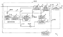
- FIG. 1 is a functional block diagram illustrating an image processing apparatus according to a first embodiment of the present invention.
- the image processing apparatus 1 is formed by, for example a digital signal processor, which is processing means.
- the processing means performs a predetermined processing program, and thereby transforms the resolution of the image data D 1 , which is input-image data, into the resolution specified by a controller, not shown, to output the data.
- the image processing apparatus 1 generates output-image data D 3 , which has been enlarged or contracted from the image data D 1 , and outputs the data to display means, etc.
- the processing program for the processing means is provided by being pre-installed in the image processing apparatus in this embodiment.
- a processing program may be provided, for example, by being downloaded through a network such as the Internet, or the like.
- the processing program may be provided through various recording media.
- various recording media such as an optical disc, a memory card, a removable hard disk, etc., can be widely used for such recording media.
- an interpolation processing unit 2 transforms the resolution of the image data D 1 by, for example linear interpolation processing, bicubic transformation processing to output a pixel value Pa with the sampling pitch corresponding to the output-image data D 3 .
- Image processing units 3 A to 3 E detect an edge-gradient direction having a largest gradient of each pixel value and an edge direction orthogonal to the edge-gradient direction for each pixel of the input-image data D 1 , and performs edge-enhancement processing and smoothing processing on the input-image data in the edge-gradient direction and the edge direction, respectively, in order to transform the resolution of the image data D 1 to the resolution of the output-image data D 3 .
- the image processing units 3 A to 3 E integrate the result of the resolution transformation by a series of processing with image data S 11 by the pixel value Pa output from the interpolation processing unit 2 to output the processing result as image data D 2 A to D 2 E. Thus, excessive contour-enhancement in a natural image is effectively avoided.
- the image processing units 3 A to 3 E have the same configuration with the exception of having different characteristics for the detection of the edge-gradient direction and the edge direction.
- a layer integration unit 4 integrates the processing results of the plurality of the image processing units 3 A to 3 E to output the output-image data D 3 .
- the image processing apparatus 1 integrates the processing results by various characteristics to generate the output-image data D 3 . Accordingly, the image processing apparatus 1 reliably prevents the loss of high frequency components and the occurrence of jaggy, and transforms the resolution of the image data D 1 even in the case of displaying a specific pattern, etc.
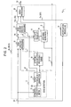
- FIG. 2 is a block diagram illustrating a detailed configuration of the image processing unit 3 A.
- an edge detection unit 12 detects an edge-gradient direction having a largest gradient of a pixel value and an edge direction orthogonal to the edge-gradient direction for each pixel of the image data D 1 . That is to say, in the edge detection unit 12 , a gradient-matrix generation unit 13 sequentially changes a remarked pixel, for example in the order of raster scanning, and generates a matrix G of the luminance gradient expressed by the following expression for each pixel by the processing using pixel values in a range W with a remarked pixel as center as shown in FIG. 3 .
- FIG. 3 is an example in which ⁇ 3 pixels in the x-direction and in the y-direction with a remarked pixel as center are set within the range W.
- w(i, j) is a Gaussian weight expressed by Expression (2)
- g is a luminance gradient expressed by Expression (3) using an x-direction partial differential gx of an image luminance I and a y-direction partial differential gy of the image luminance I.
- the gradient-matrix generation unit 13 detects the luminance gradient produced by performing weighting processing on the predetermined range W with a remarked pixel as center on the basis of the remarked pixel.
- a subsequent eigenvalue-and-eigenvector detection unit 14 processes the matrix G of the luminance gradient generated by the gradient-matrix generation unit 13 , and thereby detects an edge-gradient direction v 1 having a largest gradient of a pixel value and an edge direction v 2 orthogonal to the edge-gradient direction v 1 for the remarked pixel. Also, the eigenvalue-and-eigenvector detection unit 14 detects eigenvalues ⁇ 1 and ⁇ 2 indicating the variances of the gradients of individual pixel values in the edge-gradient direction v 1 and in the edge direction v 2 .
- the eigenvalue-and-eigenvector detection unit 14 detects the eigenvalues ⁇ 1 and ⁇ 2 ( ⁇ 1 ⁇ 2 ) in the edge-gradient direction v 1 and in the edge direction v 2 , respectively, by the processing of the following expressions.
- An edge-direction processing unit 15 calculates an edge direction vc of each pixel of image data D 2 after resolution transformation on the basis of the edge direction v 2 of the remarked pixel of the image data D 1 detected by the edge detection unit 12 in this manner, and sequentially calculates pixel values corresponding to each pixel Pc of the output-image data D 2 .
- the edge-direction processing unit 15 performs the processing of the following expression on each pixel (P 3 , P 4 , P 9 , and P 10 in the example in FIG. 5 ) of the image data D 1 adjacent to a pixel (in the following, called as a remarked pixel of the image data D 2 ) Pc of the output-image data D 2 to be calculated.
- the edge-direction processing unit 15 calculates the edge direction vc of the remarked pixel Pc by interpolation processing using the edge direction v 2 (v 3 , v 4 , v 9 , and v 10 ) of the adjacent pixels of the image data D 1 .
- tx and ty are coordinate values of the remarked pixel internally dividing the sampling points P 3 , P 4 , P 9 , and P 10 of the image data D 1 in the x-direction and in the y-direction, respectively.
- the edge-direction processing unit 15 sets a predetermined number of sampling points P- 2 , P- 1 , P 1 , and P 2 in the line in the edge direction vc from the sampling points of the remarked pixel Pc with the sampling pitch of the image data D 1 using the edge direction vc of the remarked pixel Pc calculated in this manner.
- the edge-direction processing unit 15 calculates each pixel value of the sampling points P- 2 , P- 1 , P 1 , and P 2 , and the remarked pixel Pc by the interpolation processing using the pixel values of the image data D 1 .
- the edge-direction processing unit 15 generates interpolation image data in the edge direction by the interpolation processing of the input-image data D 1 in a line extending in the edge direction vc for each pixel of the output-image data D 2 on the basis of the detection result of the edge detection unit 12 .
- the edge-direction processing unit 15 changes the number of the sampling points set in this manner in accordance with the calculation result by an edge-direction processing range determination unit 16 described below, also changes the subsequent filtering processing, and thus changes the number of taps of the filtering processing in accordance with the reliability of the edge of the remarked pixel in the edge direction vc.
- the pixel value of the remarked pixel Pc is calculated by linear interpolation using the surrounding pixels P 3 , P 4 , P 9 , and P 10 .
- the pixel values of the adjacent sampling points P- 1 and P 1 are calculated by linear interpolation using P 2 , P 3 , P 8 , and P 9 , and P 4 , P 5 , P 10 , and P 11 , respectively, in the same manner.
- the pixel value of the remarked pixel Pc is calculated by the linear interpolation using the surrounding pixels P 3 , P 4 , P 9 , and P 10 , and the pixel values of the sampling points P- 2 , P- 1 , P 1 and P 2 are calculated in the same manner.
- the edge-direction processing unit 15 performs smoothing processing on the pixel values of the sampling points P- 2 , P- 1 , P 1 and P 2 , and the remarked pixel Pc calculated in this manner to determine the pixel value Pc′ of the remarked pixel Pc. That is to say, in the case of filtering with three taps, for example, the pixel value Pc′ of the remarked pixel Pc is calculated by the processing of the following expression.
- the pixel value Pc′ of the remarked pixel Pc is calculated by the processing of the following expression.
- the pixel values corresponding to the pixels of the output-image data D 2 are calculated by the smoothing processing of the interpolation image data in the edge direction.
- various interpolation processing using various surrounding pixels can be widely applied in addition to the linear interpolation using the pixel values of the adjacent pixels in the vicinity.
- the interpolation processing is not limited to the above-described processing by the expressions (10) and (11), and interpolation processing by various weighting coefficients can be widely applied.
- the smoothing processing might be performed in the direction orthogonal to the luminance gradient at the portions without edges.
- the image quality becomes rather deteriorated if the filtering processing is performed with a large number of taps in a large range.
- the filtering processing is performed in a large range, it is possible to reliably prevent the occurrence of jaggy furthermore, and thus smooth edges can be formed.
- the number of taps for filtering portion is changed for each pixel, and thus the range of the smoothing processing in the edge direction is changed for each pixel. Also, the range of such smoothing processing is changed by the reliability of the edges in the edge direction vc, and thus the image deterioration by the smoothing processing is prevented.
- the reliability of the edge in such an edge direction vc is detected by the ratio ⁇ 2 / ⁇ 1 of the eigenvalue ⁇ 2 in the edge direction v 2 to the eigenvalue ⁇ 1 in the edge-gradient direction v 1 . That is to say, when the ratio ⁇ 2 / ⁇ 1 is small, the gradient of the pixel value in the edge-gradient direction v 1 is dominant for the remarked pixel, and the edge is determined to be intensive in the edge direction v 2 .
- the ratio ⁇ 2 / ⁇ 1 is small, the gradient of the pixel value in the edge-gradient direction v 1 is dominant for the remarked pixel, and the edge is determined to be intensive in the edge direction v 2 .
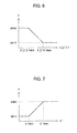
- the edge-direction processing range determination unit 16 generates the parameter p whose value increases linearly in accordance with a decrease of the value of the ratio ⁇ 2 / ⁇ 1 while the ratio ⁇ 2 / ⁇ 1 is in a certain range between ⁇ 2 / ⁇ 1 min and ⁇ 2 / ⁇ 1 max, and whose value becomes the maximum value pmax and the minimum value pmin when the value of the ratio ⁇ 2 / ⁇ 1 is outside the certain range between ⁇ 2 / ⁇ 1 min and ⁇ 2 / ⁇ 1 max, respectively.
- the parameter p which changes its value in accordance with the reliability of the edge in the edge direction, is generated.
- the edge-direction processing range determination unit 16 generates a parameter q whose value increases linearly in accordance with the value of the eigenvalue ⁇ 1 within a predetermined range between ⁇ 1 min and ⁇ 1 max, and whose value becomes the minimum value qmin and the maximum value qmax when the value of the ratio ⁇ 1 is smaller and larger than the range between ⁇ 1 min and ⁇ 1 max, respectively.
- the parameter q which changes its value in accordance with the rise of the edge, is generated.
- the edge-direction processing range determination unit 16 performs the multiplication processing expressed by the following expression on these two parameters p and q, and thus calculates the range r of the filtering processing of the edge-direction processing.
- the edge-direction processing range determination unit 16 transforms the eigenvalues ⁇ 1 and ⁇ 2 by the sampling values of the image data D 1 into the range r of the filtering processing so as to corresponds to the sampling points of the image data D 2 of the processing by the edge-direction processing unit 15 .
- the range r of the filtering processing of the image data D 2 may be calculated by the interpolation processing of this calculation result.
- the range r of the filtering processing may be calculated by the calculation result.
- the edge-direction processing unit 15 calculates the pixel value Pc′ of the remarked pixel Pc of the image data D 2 by changing the number of taps of the filtering processing by the range r calculated in this manner.
- the edge-direction processing unit 15 performs integration processing of the filtering results, and thus performing the filtering processing with a real number of taps.
- unnaturalness which occurs at the time of changing the number of taps when performing the filtering processing with an integer number of taps, is eliminated.
- the edge-direction processing unit 15 defines a filter with an integer number of taps shown by the following expression.
- odd numbers 1, 3, 5, . . . is applied to the integer number of taps.
- floor (n) is a maximum integer number of taps which does not exceed n
- ceil (n) is a minimum integer of taps of n or more.
- the integration processing of the filtering results is performed by means of the calculation of the filtering processing result f(n) with a real number by executing the processing of the following expression using these two kinds of filtering processing results.
- the edge-direction processing unit 15 performs the filtering processing using these two kinds of the numbers of taps depending on the range r of the filtering processing.
- the edge-direction processing unit 15 performs the processing of the expression (14) using these two kinds of filtering processing results to calculate the pixel value Pc′ of the remarked pixel Pc of the image data D 2 .
- the edge-direction processing unit 15 performs the filtering processing by the numbers of taps in accordance with the reliability of the edge in the edge direction to calculate the pixel value Pc′ of the remarked pixel Pc of the image data D 2 , and thereby makes it possible to change the number of taps by the fractional part of a decimal.
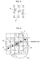
- An edge-gradient direction processing unit 17 performs contour enhancement processing in the edge-gradient direction v 1 using the pixel value Pc′ of the remarked pixel Pc of the image data D 2 calculated by the edge-direction processing unit 15 in this manner. That is to say, as shown in FIG. 8 , the edge-gradient direction processing unit 17 calculates the edge-gradient direction vg of the remarked pixel Pcc of the image data D 2 by the edge-gradient direction v 1 of the adjacent sampling points of the image data D 1 in the same manner as the edge-direction processing unit 15 calculates the edge direction vc of the remarked pixel Pc of image data D 2 .
- the edge-gradient direction processing unit 17 sets a predetermined number of sampling points Pc ⁇ 1 and Pc+1 in the line in the edge-gradient direction vg from the sampling points of the remarked pixel Pcc with the sampling pitch of the image data D 2 using the edge-gradient direction vg of the remarked pixel Pcc calculated in this manner.
- the edge-gradient direction processing unit 17 calculates each pixel value of the sampling points Pc ⁇ 1 and Pc+1, and the remarked pixel Pcc by the interpolation processing using the pixel values output from the edge-direction processing unit 15 .
- the edge-gradient direction processing unit 17 generates interpolation image data in the edge-gradient direction by the interpolation processing of the image data output from the edge-direction processing unit 15 in a line extending in the edge-gradient direction vg for each pixel of the output-image data D 2 on the basis of the detection result of the edge detection unit 12 .
- the edge-gradient direction processing unit 17 performs filtering processing on the pixel values of the sampling points Pc ⁇ 1 and Pc+1, and the remarked pixel Pcc calculated in this manner to determine the pixel value Pcc′ of the remarked pixel Pcc.
- the example in FIG. 8 is the case where the pixel value Pcc′ of the remarked pixel Pcc is calculated by three taps.
- the pixel value of the sampling point Pc ⁇ 1 is generated by the linear interpolation by the surrounding sampling points Pc 1 , Pc 2 , Pc 4 , and Pcc.
- the pixel value of the sampling point Pc+1 is generated by the linear interpolation by the surrounding sampling points Pcc, Pc 5 , Pc 7 , and Pc 8 .
- the edge-gradient direction processing unit 17 enhances contour in the direction of crossing the edge.
- various interpolation processing using various surrounding pixels can be widely applied in addition to the linear interpolation using the pixel values of such adjacent pixels in the vicinity.
- interpolation processing by various weighting coefficients can be widely applied for the processing of the filtering processing using the interpolation image data.
- a reliability calculation unit 18 calculates reliabilities f in the edge-gradient direction and the edge direction. For this purpose, as shown in FIG. 9 , the reliability calculation unit 18 sets sampling points Pa, Pb, Pc, and Pd (indicated by a black circle) for calculating the reliability at a certain sampling pitch before and after the remarked pixel in the vicinity in the edge direction v 2 using the edge direction v 2 of the remarked pixel to be processed to obtain the pixel value of each of the sampling values Pa, Pb, Pc, and Pd by the pixel values output from the edge-direction processing unit 15 .
- the reliability calculation unit 18 performs the interpolation processing of the pixel values of the surrounding pixels of each sampling point to obtain the pixel values of each of the sampling values Pa, Pb, Pc, and Pd.
- the example in FIG. 9 is the case where a sampling pitch in the horizontal direction is set to the sampling pitch of the output-image data D 2 , and two sampling points are set before and after the remarked pixel, respectively.
- the reliability calculation unit 18 sets sub-sampling points (indicated by a white circle) for calculating each reliability before and after the sampling points Pa, Pb, Pc, Pd, and the remarked pixel in the edge-gradient direction v 1 using the edge-gradient direction v 1 at the remarked pixel to obtain the pixel value of each sub-sampling point from the corresponding pixel value output from the edge-direction processing unit 15 .
- the reliability calculation unit 18 also performs the interpolation processing of the pixel values of the surrounding pixels of each sub-sampling point to obtain the pixel values of the individual sub-sampling points.
- the example in FIG. 9 is the case where a sampling pitch in the vertical direction is set to the sampling pitch of the output-image data D 2 , and one sampling point is set before and after each sampling point and the remarked pixel in the edge direction v 2 .
- the reliability calculation unit 18 calculates the summations ⁇ 1 to ⁇ 5 among the pixel values of the sub-sampling points before and after in the edge-gradient direction v 1 individually for the remarked pixel and the pixels of the sampling points Pa, Pb, Pc, and Pd before and after the remarked pixel in the edge direction v 2 .
- the reliability calculation unit 18 calculates the summations ⁇ 1 to ⁇ 5 among the pixel values of the sub-sampling points before and after in the edge-gradient direction v 1 individually for the remarked pixel and the pixels of the sampling points Pa, Pb, Pc, and Pd before and after the remarked pixel in the edge direction v 2 .
- a clear edge is formed in the edge-extension direction
- nearly the same values are obtained from the summations ⁇ 1 to ⁇ 5 calculated in this manner.
- these summations ⁇ 1 to ⁇ 5 have values that vary greatly.
- the reliability calculation unit 18 calculates the subtraction values between the summations of adjacent sampling points ⁇ 1 and ⁇ 2 , ⁇ 2 and ⁇ 3 , ⁇ 3 and ⁇ 4 , and ⁇ 4 and ⁇ 5 . Also, the reliability calculation unit 18 obtains the absolute value of each subtraction value calculated in this manner, and adds the absolute values to obtain the additional vale SAD.
- the reliability calculation unit 18 generates a parameter e whose value decreases linearly in accordance with SAD within a predetermined range between SADmin and SADmax, and whose value becomes the upper limit value 1.0 and the lower limit value 0 when SAD is smaller and larger than the range between SADmin and SADmax, respectively.
- the reliability calculation unit 18 sets sampling points at regular intervals in the edge direction, and obtains pixel values at the sampling points from the input-image data D 1 in order to detect the reliability by comparing the pixel values. Also, at this time, the reliability calculation unit 18 sets sampling points before and after individual sampling points in the edge-gradient direction, and obtains the pixel values of individual sampling points from the total of the pixel values of the sampling points.
- the reliability calculation unit 18 calculates subtraction values diffh 1 , diffh 2 , diffv 1 , and diffv 2 by individually subtracting the pixel values I ⁇ 1 and I+1, which are adjacent to the remarked pixel in the horizontal direction, and I ⁇ v and I+v, which are adjacent to the remarked pixel in the vertical direction from the pixel value I 0 of a remarked pixel on the basis of the corresponding pixel values output from the edge-direction processing unit 15 .
- the reliability calculation unit 18 determines whether the subtraction values diffh 1 and diffh 2 in the horizontal direction, and the subtraction values diffv 1 and diffv 2 in the vertical direction have the same signs or not, respectively, as shown by the following expressions.
- the absolute values are obtained from the pair of subtraction values in the direction of matching, respectively, and then a smaller one of the absolute values is selected to be used for integrated difference values diffh and diffv in the horizontal direction and the vertical direction, respectively. Also, if the signs do not match, the integrated difference values diffh and diffv in the horizontal direction and the vertical direction, respectively, is set to 0.
- a larger one of the integrated difference values diffh and diffv in the horizontal direction and the vertical direction, respectively, calculated in this manner, is selected to be a parameter diff for calculating the reliability as shown by the following expression.
- the reliability calculation unit 18 generates a parameter s 0 whose value decreases linearly in accordance with the parameter diff within a predetermined range between diffmin and diffmax, and whose value becomes the upper limit value 1.0 and the lower limit value 0 when the parameter diff is smaller and larger than the range between diffmin and diffmax, respectively.
- the reliability parameter s 0 obtained in this manner and the reliability parameter e are multiplied to generate the parameter f indicating the reliability of the edge.
- the reliability calculation unit 18 calculates the difference values with the pixel values of the adjacent pixels in the vertical direction and the horizontal direction to detect the reliability.
- the input-image data D 1 may be used in place of the output data of the edge-direction processing unit 15 .
- a blend-ratio determination unit 19 generates weighting coefficients for blending in accordance with the reliabilities of the edges in the edge direction vc. That is to say, as described above, when smooth processing is performed in the edge direction and contour-enhancement is performed in the direction orthogonal to the edge, excessive contour-enhancement sometimes occurs in a natural image. Accordingly, in this embodiment, the pixel value Pa of the image data D 2 generated by a known method in the interpolation processing unit 2 and the pixel value Pcc′ generated separately by the edge-gradient direction processing unit 17 are added with weighting by a blend processing unit 20 to produce the image data D 2 . The blend-ratio determination unit 19 changes the weighting coefficient of the addition processing with weighting.
- the weighting coefficient is changed by changing the reliability of the edge in the edge direction, and thus unnaturalness of the excessive edge processing is prevented. Also, the ratio ⁇ 2 / ⁇ 1 of the eigenvalue ⁇ 2 in the edge direction v 2 to the eigenvalue ⁇ 1 in the edge-gradient direction v 1 and the reliability f calculated by the reliability calculation unit 18 are applied to the reliability of the edge in the edge direction.
- the gradient of the pixel value in the edge-gradient direction v 1 is dominant in the remarked pixel, and the edge is determined to be intensive in the edge direction v 2 .
- the blend-ratio determination unit 19 generates a parameter s whose value increases linearly in accordance with a decrease of the value of the ratio ⁇ 2 / ⁇ 1 while the ratio ⁇ 2 / ⁇ 1 is in a certain range between ⁇ 2 / ⁇ 1 min and ⁇ 2 / ⁇ 1 max, and the whose value becomes the maximum value smax and the minimum value smin when the value of the ratio ⁇ 2 / ⁇ 1 is outside the certain range between ⁇ 2 / ⁇ 1 min and ⁇ 2 / ⁇ 1 max, respectively.
- the parameter s which changes its value in accordance with the reliability of the edge in the edge direction, is generated.
- the blend-ratio determination unit 19 generates a parameter t whose value increases linearly in accordance with the value of the eigenvalue ⁇ 1 within a predetermined range between ⁇ 1 min and ⁇ 1 max, and whose value becomes the minimum value tmin and the maximum value tmax when the value is ⁇ 1 min and ⁇ 1 max, respectively.
- the parameter t which changes its value in accordance with the rise of the edge, is generated.
- the blend-ratio determination unit 19 multiplies these parameters s and t, and the parameter f of the reliability calculated by the reliability calculation unit 18 to calculate the weighting coefficient ⁇ (0 ⁇ 1) for the blend processing.
- the blend-ratio determination unit 19 transforms the eigenvalues ⁇ 1 and ⁇ 2 of the sampling values of the image data D 1 into the eigenvalues of the sampling values of the image data D 2 so as to corresponds to the sampling points of the image data D 2 in order to calculate the weighting coefficient ⁇ for blending.
- a blend processing 20 performs weighted addition processing between the image data S 3 based on the pixel values Pcc′ calculated by the edge-gradient direction processing unit 17 and the image data S 11 based on the pixel values Pa calculated by the interpolation processing unit 2 using the weighting coefficient ⁇ by the blend-ratio determination unit 19 , and outputs the processing result as the image data D 2 .
- the image processing units 3 A to 3 E detects an edge-gradient direction having a largest gradient of each pixel value and an edge direction orthogonal to the edge-gradient direction for each pixel, and performs edge-enhancement processing and smoothing processing in each direction, respectively. Also, the image processing units 3 A to 3 E are set to have different characteristics to be used for the detection of the edge-gradient direction and the edge direction by the settings of the differential operators used by the gradient-matrix generation unit 13 for calculating the x-direction partial differential gx and the y-direction partial differential gy.
- the first to the fifth image processing units 3 A to 3 E individually calculate the x-direction partial differential gx and the y-direction partial differential gy by the differential operators expressed by the expressions (21) to (25). Accordingly, in this image processing apparatus 1 , the plurality of image processing units 3 A to 3 E have different phase characteristics of the differential operators, and different characteristics being set for use with detecting the edge-gradient direction and the edge direction. Thus, if one image processing unit is difficult to detect the edge direction or the edge-gradient direction, a detection error has occurred, or the like, any one of the other image processing units can correctly detect the edge direction or the edge-gradient direction. In this regard, for these differential operators, frequency characteristics may be set differently in place of, or in addition to the phase characteristics.
- the layer integration unit 4 sets the weighting coefficient ⁇ of the image data D 2 A to D 2 E output from individual image processing units 3 A to 3 E in accordance with the ratio of the variance ⁇ 1 of the gradients of the pixel values in the edge direction to the variance ⁇ 2 of the gradients of the pixel values in the edge-gradient direction, and adds the image data D 2 A to D 2 E with weighting by the weighting coefficient ⁇ in order to generate the output-image data D 3 as shown by the following expression.
- the differential operators are set symmetrically between the second and the fifth image processing units 3 B and 3 E, and the third and the fourth image processing units 3 C and 3 D, respectively, on the basis of the setting of the differential operator of the first image processing unit 3 A.
- the layer integration unit 4 generates the weighting coefficient using the variances ⁇ 1 and ⁇ 2 detected by the first image processing unit 3 A to be the basis.
- FIG. 15 is characteristic curves illustrating an example of the settings of the weighting coefficients ⁇ 0 to ⁇ 4 .
- the example in FIG. 15 illustrates the settings of the weighting coefficients in two image processing units in which differential operators are set symmetrically.
- the layer integration unit 4 sets the weighting coefficients so as to change the values complementarily for each group of image processing units having the differential operators set symmetrically in a predetermined range.
- the weighting coefficients ⁇ 0 and ⁇ n, and ⁇ 1 and ⁇ n ⁇ 1 are set to form a group, respectively.
- layer integration unit 4 normalizes the results of the addition with weighting such that the total value of the weighting coefficients becomes the value 1, and outputs the output-image data D 3 .
- the weighting coefficients of the individual image processing units 3 A to 3 E may be set by the variances ⁇ 1 and ⁇ 2 detected by the individual image processing units 3 A to 3 E to perform weighted addition, and then normalization may be performed.
- the input-image data D 1 is input to the edge detection unit 12 of the first image processing unit 3 A.
- the edge-gradient direction v 1 having a largest gradient of a pixel value and the edge direction v 2 orthogonal to the edge-gradient direction v 1 for each pixel are detected in sequence (Expressions (1) to (8), FIGS. 3 and 4 ).
- the input-image data D 1 is input to the edge-direction processing unit 15 .
- the image data is subjected to smooth processing in the edge direction v 2 for each pixel of the output-image data D 2 on the basis of the detection result of the edge detection unit 12 , and the pixel value Pc corresponding to each pixel of the output-image data D 2 is calculated in sequence (Expressions (9) to (14), FIG. 5 ) Also, the pixel value Pc from the calculation result is input to the edge-gradient direction processing unit 17 .
- the contour enhancement processing in the edge-gradient direction v 1 is performed for each pixel of the output-image data D 2 on the basis of the detection result of the edge detection unit 12 in order to calculate the pixel values of the output-image data D 2 (Expressions (9) to (14), FIG. 8 ).
- the input-image data D 1 is subjected to the smooth processing in the edge direction v 2 , thereby the occurrence of jaggy is effectively prevented.
- the contour enhancement is performed in the edge-gradient direction v 1 orthogonal to the edge direction v 2 , and thus high frequency components are enhanced in the direction orthogonal to the edge direction. Accordingly, the input-image data D 1 is transformed into the image data D 2 while the loss of high frequency components is effectively avoided and the occurrence of jaggy is prevented.
- edges are sometimes difficult to be detected correctly depending on the characteristic used for detecting the edge direction and the edge-gradient direction, and thus edges of a specific pattern is difficult to be correctly processed, for example.
- the input-image data D 1 is also input to the second to the fifth image processing units 3 B to 3 E having the same configuration as the first image processing unit 3 A and different characteristics to be used for the detection of the edge direction and the edge-gradient direction, and is individually subjected to the smoothing processing and the contour enhancement processing by the detection of the edge direction and the edge-gradient direction in the same manner as the image processing unit 3 A.
- the processing results by the first to the fifth image processing units 3 A to 3 E are integrated by the layer integration unit 4 (Expression (26)).
- the image processing apparatus 1 if one of the five image processing units 3 A to 3 E is difficult to detect the edge direction and the edge-gradient direction, a detection error has occurred, or the like, the other image processing units can correctly detect the edge direction and the edge-gradient direction. Accordingly, the image quality can be reliably improved by preventing dissimilarity and roughness. Also, the discrimination ability between edges and texture is improved, and thereby making it possible to improve image quality.
- the input-image data D 1 is subjected to a series of processing.
- the gradient-matrix generation unit 13 of the edge detection unit 12 generates the matrix G of the luminance gradient for each pixel.
- the matrix G of the luminance gradient is subject to the processing by the subsequent eigenvalue-and-eigenvector detection unit 14 , and thus the edge-gradient direction v 1 and the edge direction v 2 are detected.
- each of the image processing units 3 A to 3 E the differential operator used for the generation of the matrix G of the luminance gradient is set to have different phase characteristic (Expressions (21) to (25)).
- the edge direction and the edge-gradient direction are individually performed by different characteristics.
- the image processing apparatus 1 is provided with a plurality of the image processing units 3 A to 3 E having different characteristics. These image processing units 3 A to 3 E have almost the same configuration, and the entire processing can be simplified to that extent.
- an input-video signal S 1 is subjected to the processing of the matrix G of the luminance gradient to calculate the eigenvalues ⁇ 1 and ⁇ 2 indicating the variances of the gradients of the pixel values in the edge-gradient direction v 1 and the edge direction v 2 .
- the ratio ⁇ 2 / ⁇ 1 of the eigenvalues ⁇ 1 and ⁇ 2 indicates the reliability in the edge direction. If the ratio ⁇ 2 / ⁇ 1 is small, the edge can be rather correctly processed when the processing results of the other processing units is employed.
- the image processing apparatus 1 the eigenvalues ⁇ 1 and ⁇ 2 detected by the first image processing unit 3 A are input to the layer integration unit 4 , and the weighting coefficient ⁇ of the processing result by each of the image processing units 3 A to 3 E is calculated in accordance with the ratio ⁇ 2 / ⁇ 1 of the eigenvalues ⁇ 1 and ⁇ 2 here ( FIG. 15 ).
- the output-image data D 3 is generated by the weighted addition using this weighting coefficient ⁇ (Expression (26)). Accordingly, the image processing apparatus 1 can improve image quality furthermore.
- the edge-direction processing range determination unit 16 generates the parameter p indicating the reliability of the edge by the ratio ⁇ 2 / ⁇ 1 of the eigenvalues ⁇ 1 and ⁇ 2 ( FIG. 6 ). Also, the eigenvalue ⁇ 1 indicates the intensity of the edge, and thus the parameter q corresponding to the parameter p is generated ( FIG. 7 ). Also, the range r of the filtering processing is calculated in the edge-direction processing unit 15 by the multiplication of these parameters p and q.
- the edge-direction processing unit 15 performs the filtering processing on the interpolation image data Pc in the edge direction of the input-image data D 1 to generate the pixel value Pc′ of the output-image data D 2 , the number of taps for the filtering portion is changed by the range r of the filtering processing generated by the edge-direction processing range determination unit 16 in this manner. If the reliability of the edge is high, the interpolation image data Pc in the edge direction is subjected to the filtering processing with a wide range to generate the pixel value Pc′ of the output-image data D 2 .
- the interpolation image data Pc in the edge direction is subjected to the filtering processing with a narrow range to generate the pixel value Pc′ of the output-image data D 2 .
- the number of taps of the filtering processing in the edge direction v 2 is changed depending on the reliability of the edge (Expressions (10) to (14)). Accordingly, excessive smoothing processing at the portions except the edge is prevented, and the deterioration of the image is effectively avoided.
- the weighting coefficient ⁇ of the filtering processing is changed (Expression (12)) in accordance with the reliability of the edge in the edge direction v 2 .
- the weighted addition is performed on the filtering processing results using this weighting coefficient ⁇ (Expression (14)).
- the number of taps is changed by the fractional part of a decimal. Accordingly, unnaturalness, which occurs at the time of changing the number of taps when performing the filtering processing with an integer number of taps, is eliminated.
- the processing result by each of the image processing units 3 A to 3 E sometimes contains excessive contour enhancement in a picture of nature.
- the image data D 1 is subjected to the interpolation processing by a known method in the interpolation processing unit 2 to calculate the pixel value Pa′ of the output-image data D 2 for each pixel.
- the image data S 11 generated by the interpolation processing unit 2 by the know method has lost high-frequency components, but has not undergone contour enhancement excessively.
- the image data S 11 from the interpolation processing unit 2 and the image data S 3 from the edge-gradient direction processing unit 17 are subjected to weighted addition processing in accordance with the image to generate the output-image data D 2 (Expression (20)).
- the parameter s indicating the reliability of the edge by the ratio ⁇ 2 / ⁇ 1 of the eigenvalues ⁇ 1 and ⁇ 2 is calculated by the blend-ratio determination unit 19 ( FIG. 13 ).
- the parameter t indicating the reliability of the edge is generated by the eigenvalue ⁇ 1 in the same manner ( FIG.
- the portion having excessive contour enhancement is subjected to correction by the pixel value Pa′ by the known method to generate the output-image data D 2 . Accordingly, in this embodiment, the deterioration of the image quality due to the excessive contour enhancement is prevented.
- the reliability calculation unit 18 sets sampling points at certain intervals before and after the remarked pixel in the edge direction v 2 , and obtains the pixel value of each sampling point by the output data of the edge-direction processing unit 15 .
- the reliability parameter e indicating the reliability in the edge-gradient direction and the edge direction is detected (Expression (18), FIGS. 9 and 10 ).
- the weighting coefficient ⁇ generated by the blend-ratio determination unit 19 is corrected by the reliability parameter e (Expression (19)), and thus erroneous processing for a specific processing is prevented.
- such a specific pattern is, for example the case where a line is perpendicular to an edge having a big change of a signal level, the case of having two edges crossed with each other, or the like.
- the reliability calculation unit 18 sets sub-sampling points before and after individual sampling points in the edge-gradient direction v 1 , and obtains the pixel values of individual sampling points from the total of the pixel values of the sub-sampling points. Thus, erroneous processing on such a specific pattern is reliably prevented.
- the reliability calculation unit 18 calculates the difference of the values between the remarked pixel and the adjacent pixels in the vertical direction and in the horizontal direction, and the comparison of these difference values detect the reliability parameter s 0 indicating the reliability in the edge-gradient direction and in the edge direction (Expressions (15) to (17), FIGS. 11 and 12 ). Also, the weighting coefficient ⁇ generated by the blend-ratio determination unit 19 is also corrected by the reliability parameter s 0 (Expression (19)), and thus erroneous processing for a specific processing is prevented. In this regard, such a specific pattern is, for example the case where light and darkness are repeated mosaically with a pixel pitch, or the like.
- the edge-enhancement processing and the smoothing processing are performed in an edge-gradient direction having a largest gradient of a pixel value and an edge direction orthogonal to the edge-gradient direction, respectively, in order to improve image quality. Also, the edge-gradient direction and the edge direction are detected by different characteristics, the edge-enhancement processing and the smoothing processing are performed for each characteristic, and then the processing result of each characteristic is integrated. Thus, the loss of high frequency components and the occurrence of jaggy are prevented in order to reliably improve image quality.
- Each of the image processing units is provided with an edge detection unit for detecting the edge-gradient direction and the edge direction, an edge-direction processing unit for performing smoothing processing in the edge direction on the basis of the detection result of the edge detection unit, and an edge-gradient direction processing for performing contour enhancement processing in the edge-gradient direction on the basis of the detection result of the edge detection unit.
- an edge detection unit for detecting the edge-gradient direction and the edge direction
- an edge-direction processing unit for performing smoothing processing in the edge direction on the basis of the detection result of the edge detection unit
- an edge-gradient direction processing for performing contour enhancement processing in the edge-gradient direction on the basis of the detection result of the edge detection unit.
- the edge detection unit detects the edge-gradient direction and the edge-direction by differentiating pixel values in a certain range with a pixel to be processed as center, and the plurality of image processing units have different differential operators being set for use with differentiating the pixel values in order to have different characteristics being set for use with detecting the edge-gradient direction and the edge direction.
- major components of the plurality of the image processing units have common configurations, and thereby the entire configuration and the entire processing can be simplified.
- each of the image processing units is provided with a reliability calculation unit for detecting the reliabilities in the edge-gradient direction and the edge-direction, and a blend processing unit for correcting the pixel values output from the edge-gradient direction processing unit based on the pixel values of the input-image data in accordance with the reliabilities detected by the reliability calculation unit.
- sampling points are set at certain intervals before and after the remarked pixel in the edge direction, and the reliability is detected by the comparison of the pixel values of the sampling points.
- sub-sampling points are individually set before and after the remarked pixel and sampling points in the edge-gradient direction, and the pixel value of each sampling point is obtained from the total value of the pixel values of the sub-sampling points.
- the difference of the values between the remarked pixel and the adjacent pixels in the vertical direction and in the horizontal direction are calculated, and the comparison of these difference values detects the reliability, and thus erroneous processing for a specific processing such as the case where light and darkness are repeated mosaically with a pixel pitch can be prevented. Accordingly, it is also possible to improve image quality.
- the integration unit which integrates the processing results of the plurality of the image processing units, sets the weighting coefficient of the image data output from each of the image processing units in accordance with the ratio of the variance of the gradients of the pixel values in the edge direction to the variance of the gradients of the pixel values in the edge-gradient direction.
- the image data is added with weighting by the weighting coefficient.
- FIG. 16 is a block diagram illustrating an image processing unit to be applied to an image processing apparatus according to a second embodiment of the present invention.
- This image processing apparatus has the same configuration as that of the image processing apparatus 1 according to the first embodiment except that image processing units 33 B to 33 E shown in FIG. 16 are applied in place of the second to fifth image processing units 3 A to 3 E described above. Also, in the image processing units 33 B to 33 E shown in FIG. 16 , the same components as those in the first image processing unit 3 A are marked with the corresponding reference numerals, and the duplicated description will be omitted.
- edge detection units 12 and 42 of the first image processing unit 3 A and the image processing units 33 B to 33 E certain ranges used for the edge-gradient direction and the edge direction are set to be different with each other, and thus the characteristics used for detecting the edge-gradient direction and the edge direction are set to be different with each other.
- the input data D 1 is input to the gradient-matrix generation unit 13 through down-converters 43 B to 43 E, respectively.
- the down-converter 43 B of the second image processing unit 33 B reduces the number of sampling of the input-image data D 1 to 1 ⁇ 2 in the vertical direction and the horizontal direction, and outputs the data.
- the down-converters 43 C and 43 D of the third and the fourth image processing units 33 C and 33 D reduce the number of sampling of the input-image data D 1 to 1 ⁇ 4 and 1 ⁇ 8, respectively, in the vertical direction and the horizontal direction, and output the data.
- the down-converter 43 E of the fifth image processing unit 33 E reduces the number of sampling of the input-image data D 1 to 1/16 in the vertical direction and the horizontal direction, and outputs the data.
- the down-converters 43 B to 43 E reduce the number of sampling the input-image data D 1 by the reduction of the number of sampling by thinning, or by the reduction of the number of sampling using filters.
- the image processing units 33 B to 33 E up-convert the output value of the edge-direction processing range determination unit 16 and the eigenvalues ⁇ 1 and ⁇ 2 to be input to the blend-ratio determination unit 19 by the up-converters 44 B to 44 E and 45 B to 45 E, respectively.
- the up-converters 44 B to 44 E and 45 B to 45 E perform up-converting processing by an increase of sampling number by front-end interpolation, or an increase of sampling number using filters.
- the different ranges are set by the settings of the number of sampling used for the down sampling of the input image data, and thus the major configuration of the plurality of image processing units can be made uniform. Accordingly, the entire configuration and processing can be simplified to that extent.
- the up-convert processing is performed at the input of the edge direction processing and the blend-ratio determination unit 19 .
- the up-convert processing may be set at various places as necessary, for example, may be performed at the output stage of each image processing unit, etc.
- the edge-direction processing unit 15 and the edge-gradient direction processing unit 17 it becomes necessary for the edge-direction processing unit 15 and the edge-gradient direction processing unit 17 to process image data by down-converting.
- the number of sampling is sequentially reduced to 1 ⁇ 2 both in the vertical direction and in the horizontal direction.
- the present invention is not limited to this.
- the number of sampling may be reduced to 1 ⁇ 2 either in the vertical direction or in the horizontal direction.
- the combination of these may be used, etc.
- the direction of down-converting may be set in various ways.
- the ranges used for detecting the edge direction and the edge-gradient direction are set to be different in a plurality of image processing units by the setting of the number of sampling by down-converting.
- the present invention is not limited to this.
- the ranges used for detecting the edge-gradient direction and the edge direction may be set to be different in a plurality of image processing units by having different number of taps of the filter itself to be used for detecting the edge direction and the edge-gradient direction.
- the reliability calculation unit 18 detects the reliability parameters e and s 0 of by the two methods.
- the present invention is not limited to this. If a sufficient characteristic for practical use can be acquired, either the parameter e or s 0 may be used.
- the present invention is not limited to this.
- the number of taps may be changed in a geometrical ratio by changing the weighting coefficient of the smoothing processing.
- the present invention is not limited to this. If a sufficient characteristic for practical use can be acquired, only the ratio of the eigenvalues ⁇ 1 and ⁇ 2 may be changed. Also, various contour detection methods may be applied in place of the detection of the reliability of the edge by the ratio of the eigenvalues ⁇ 1 and ⁇ 2 and the eigenvalue ⁇ 1 . Also, excessive contour correction of the weighted processing of the blend processing occurs at the place where tree leaves are dense in a picture of nature. Thus, the contour detection may be changed by the characteristics of each portion of the image to be detected, for example by frequency characteristics, etc.
- the edge-direction processing and the edge-gradient direction processing may perform a series of processing on the output-image data having the same sampling pitch as that of the input-image data, and the interpolation processing should be omitted.
- the blend processing unit 20 may simply perform contour enhancement on the input-image data by weighted adding the output data of the edge-gradient direction processing unit 17 and the input-image data.
Landscapes
- Physics & Mathematics (AREA)
- General Physics & Mathematics (AREA)
- Engineering & Computer Science (AREA)
- Theoretical Computer Science (AREA)
- Image Processing (AREA)
- Television Systems (AREA)
- Editing Of Facsimile Originals (AREA)
- Facsimile Image Signal Circuits (AREA)
Abstract
Description
a=G xx 2+4G xy 2−2G xx G yy +G yy 2 (8)
v c=(1−t y)((1−t x)v 3 +t x v 4)+t y((1−t x)v 9 +t x v 10) (9)
P′ c=0.25×P −1+0.5×P c+0.25×P +1 (10)
r=p×q (12)
n integer −1=floor(n real)
n integer +1=ceil(n real) (13)
f(n)=αf(n integer −1)+(1−α)f(n integer +1) (14)
diffh1 =I 0 −I −1
diffh2 =I 0 −I +1
diffv1 =I 0 −I −v
diffv2 =I 0 −I +v (15)
When diffh1 and diffh2 have the same signs→diffh=min(|diffh1|,|diffh2|)
Otherwise→diffh=0
When diffv1 and diffv2 have the same signs→diffv=min(|diffv1|,|diffv2|)
Otherwise→diffv=0 (16)
diff=max(diffh,diffv) (17)
f=e·s 0 (18)
β=s×t×f (19)
S4=β×S3+(1−β)×S11 (20)
Claims (16)
Applications Claiming Priority (2)
| Application Number | Priority Date | Filing Date | Title |
|---|---|---|---|
| JP2005-034161 | 2005-02-10 | ||
| JP2005034161A JP4517872B2 (en) | 2005-02-10 | 2005-02-10 | Image processing apparatus, image processing method, program for image processing method, and recording medium recording program for image processing method |
Publications (2)
| Publication Number | Publication Date |
|---|---|
| US20060291741A1 US20060291741A1 (en) | 2006-12-28 |
| US7792384B2 true US7792384B2 (en) | 2010-09-07 |
Family
ID=36983701
Family Applications (1)
| Application Number | Title | Priority Date | Filing Date |
|---|---|---|---|
| US11/352,150 Expired - Fee Related US7792384B2 (en) | 2005-02-10 | 2006-02-10 | Image processing apparatus, image processing method, program, and recording medium therefor |
Country Status (2)
| Country | Link |
|---|---|
| US (1) | US7792384B2 (en) |
| JP (1) | JP4517872B2 (en) |
Cited By (6)
| Publication number | Priority date | Publication date | Assignee | Title |
|---|---|---|---|---|
| US20080118179A1 (en) * | 2006-11-21 | 2008-05-22 | Samsung Electronics Co., Ltd. | Method of and apparatus for eliminating image noise |
| US20100259653A1 (en) * | 2009-04-08 | 2010-10-14 | Semiconductor Energy Laboratory Co., Ltd. | Method for driving semiconductor device |
| US20120263384A1 (en) * | 2008-12-22 | 2012-10-18 | Tadanori Tezuka | Image enlargement apparatus, method, integrated circuit, and program |
| US20160155215A1 (en) * | 2014-11-27 | 2016-06-02 | Samsung Display Co., Ltd. | Image processing device, and an image processing method |
| US11024033B2 (en) | 2017-12-28 | 2021-06-01 | Samsung Electronics Co., Ltd. | Method and apparatus for processing image and computer program product thereof |
| US11076139B2 (en) * | 2018-08-16 | 2021-07-27 | Realtek Semiconductor Corporation | Color reconstruction device and method |
Families Citing this family (22)
| Publication number | Priority date | Publication date | Assignee | Title |
|---|---|---|---|---|
| JP4817000B2 (en) * | 2003-07-04 | 2011-11-16 | ソニー株式会社 | Image processing apparatus and method, and program |
| KR100548611B1 (en) * | 2003-08-07 | 2006-01-31 | 삼성전기주식회사 | Apparatus and method for edge emphasis in image processing |
| JP4534594B2 (en) * | 2004-05-19 | 2010-09-01 | ソニー株式会社 | Image processing apparatus, image processing method, program for image processing method, and recording medium recording program for image processing method |
| JP4987355B2 (en) * | 2005-10-14 | 2012-07-25 | 京セラ株式会社 | Imaging apparatus and imaging method |
| TWI372365B (en) * | 2006-09-06 | 2012-09-11 | Realtek Semiconductor Corp | Method and apparatus for directional edge enhancement |
| KR101086424B1 (en) * | 2007-01-12 | 2011-11-23 | 삼성전자주식회사 | Digital image processing device and method |
| US8396330B2 (en) * | 2007-07-24 | 2013-03-12 | Sharp Laboratories Of America, Inc. | Image upscaling based upon directional interpolation |
| US8538203B2 (en) * | 2007-07-24 | 2013-09-17 | Sharp Laboratories Of America, Inc. | Image upscaling technique |
| CN101911112B (en) * | 2007-12-25 | 2012-06-13 | 日本电气株式会社 | Image processing device,image decompressing device, image transmission system |
| TWI362629B (en) * | 2008-06-26 | 2012-04-21 | Chunghwa Picture Tubes Ltd | Image process method and apparatus |
| US8559746B2 (en) | 2008-09-04 | 2013-10-15 | Silicon Image, Inc. | System, method, and apparatus for smoothing of edges in images to remove irregularities |
| KR102104986B1 (en) * | 2009-02-06 | 2020-04-27 | 가부시키가이샤 한도오따이 에네루기 켄큐쇼 | Method for driving display device |
| JP5373592B2 (en) * | 2009-12-25 | 2013-12-18 | シャープ株式会社 | Image processing method, image processing apparatus, program, and recording medium |
| WO2012098854A1 (en) * | 2011-01-20 | 2012-07-26 | 日本電気株式会社 | Image processing system, image processing method, and image processing program |
| HRP20160199T1 (en) * | 2011-09-07 | 2016-03-25 | Shimadzu Corp | Image processing device and radiation imaging apparatus comprising same |
| IN2015DN01832A (en) * | 2012-09-14 | 2015-05-29 | Sony Corp | |
| JP2014123173A (en) * | 2012-12-20 | 2014-07-03 | Sony Corp | Image processor, imaging device, and image processing method |
| JP6116291B2 (en) * | 2013-02-27 | 2017-04-19 | オリンパス株式会社 | Image processing apparatus, image processing method, and image processing program |
| US9519975B2 (en) * | 2014-01-08 | 2016-12-13 | Hong Kong Applied Science And Technology Research Institute Co. Ltd. | Method of detecting edge under non-uniform lighting background |
| JP6418788B2 (en) * | 2014-05-26 | 2018-11-07 | キヤノン株式会社 | Image processing apparatus, image processing method, and program |
| JP6381344B2 (en) * | 2014-07-31 | 2018-08-29 | キヤノン株式会社 | Image processing apparatus, image processing method, and program |
| CN114663829B (en) * | 2022-03-02 | 2025-07-01 | 东莞市盟拓智能科技有限公司 | Foreign matter detection method, device and storage medium |
Citations (17)
| Publication number | Priority date | Publication date | Assignee | Title |
|---|---|---|---|---|
| US5245432A (en) * | 1989-07-31 | 1993-09-14 | Imageware Research And Development Inc. | Apparatus and method for transforming a digitized signal of an image to incorporate an airbrush effect |
| JPH07193716A (en) | 1993-12-27 | 1995-07-28 | Nec Corp | Edge emphasizing device |
| US5930007A (en) * | 1993-10-08 | 1999-07-27 | Matsushita Electric Industrial Co., Ltd. | Area recognizing device for image signals |
| US6175659B1 (en) * | 1998-10-06 | 2001-01-16 | Silicon Intergrated Systems Corp. | Method and apparatus for image scaling using adaptive edge enhancement |
| US6337925B1 (en) * | 2000-05-08 | 2002-01-08 | Adobe Systems Incorporated | Method for determining a border in a complex scene with applications to image masking |
| JP2002133410A (en) | 2000-10-25 | 2002-05-10 | Fuji Photo Film Co Ltd | Noise suppressing processor and recording medium |
| US6445832B1 (en) * | 2000-10-10 | 2002-09-03 | Lockheed Martin Corporation | Balanced template tracker for tracking an object image sequence |
| JP2003224715A (en) | 2002-01-31 | 2003-08-08 | Sony Corp | Image processing circuit and image processing method |
| US20030185420A1 (en) * | 2002-03-29 | 2003-10-02 | Jason Sefcik | Target detection method and system |
| US6643406B1 (en) * | 1999-07-28 | 2003-11-04 | Polaroid Corporation | Method and apparatus for performing linear filtering in wavelet based domain |
| US6735341B1 (en) * | 1998-06-18 | 2004-05-11 | Minolta Co., Ltd. | Image processing device and method and recording medium for recording image processing program for same |
| US20040105015A1 (en) * | 2002-07-12 | 2004-06-03 | Olympus Optical Co., Ltd. | Image processing device and image processing program |
| US6775031B1 (en) * | 1999-03-24 | 2004-08-10 | Minolta Co., Ltd. | Apparatus and method for processing images, image reading and image forming apparatuses equipped with the apparatus, and storage medium carrying programmed-data for processing images |
| US20040183812A1 (en) * | 2003-03-19 | 2004-09-23 | Ramesh Raskar | Reducing texture details in images |
| US20040190787A1 (en) * | 2002-12-27 | 2004-09-30 | Yoshihiro Nakami | Image noise reduction |
| US7148924B2 (en) * | 2001-06-07 | 2006-12-12 | Seiko Epson Corporation | Image processing method, image processing program, image processing apparatus, and digital still camera using the image processing apparatus |
| US7386158B2 (en) * | 2000-10-17 | 2008-06-10 | Fujifilm Corporation | Apparatus for suppressing noise by adapting filter characteristics to input image signal based on characteristics of input image signal |
-
2005
- 2005-02-10 JP JP2005034161A patent/JP4517872B2/en not_active Expired - Fee Related
-
2006
- 2006-02-10 US US11/352,150 patent/US7792384B2/en not_active Expired - Fee Related
Patent Citations (18)
| Publication number | Priority date | Publication date | Assignee | Title |
|---|---|---|---|---|
| US5245432A (en) * | 1989-07-31 | 1993-09-14 | Imageware Research And Development Inc. | Apparatus and method for transforming a digitized signal of an image to incorporate an airbrush effect |
| US5930007A (en) * | 1993-10-08 | 1999-07-27 | Matsushita Electric Industrial Co., Ltd. | Area recognizing device for image signals |
| JPH07193716A (en) | 1993-12-27 | 1995-07-28 | Nec Corp | Edge emphasizing device |
| US6735341B1 (en) * | 1998-06-18 | 2004-05-11 | Minolta Co., Ltd. | Image processing device and method and recording medium for recording image processing program for same |
| US6175659B1 (en) * | 1998-10-06 | 2001-01-16 | Silicon Intergrated Systems Corp. | Method and apparatus for image scaling using adaptive edge enhancement |
| US6775031B1 (en) * | 1999-03-24 | 2004-08-10 | Minolta Co., Ltd. | Apparatus and method for processing images, image reading and image forming apparatuses equipped with the apparatus, and storage medium carrying programmed-data for processing images |
| US6643406B1 (en) * | 1999-07-28 | 2003-11-04 | Polaroid Corporation | Method and apparatus for performing linear filtering in wavelet based domain |
| US6337925B1 (en) * | 2000-05-08 | 2002-01-08 | Adobe Systems Incorporated | Method for determining a border in a complex scene with applications to image masking |
| US6445832B1 (en) * | 2000-10-10 | 2002-09-03 | Lockheed Martin Corporation | Balanced template tracker for tracking an object image sequence |
| US7386158B2 (en) * | 2000-10-17 | 2008-06-10 | Fujifilm Corporation | Apparatus for suppressing noise by adapting filter characteristics to input image signal based on characteristics of input image signal |
| JP2002133410A (en) | 2000-10-25 | 2002-05-10 | Fuji Photo Film Co Ltd | Noise suppressing processor and recording medium |
| US7148924B2 (en) * | 2001-06-07 | 2006-12-12 | Seiko Epson Corporation | Image processing method, image processing program, image processing apparatus, and digital still camera using the image processing apparatus |
| US7616240B2 (en) * | 2001-06-07 | 2009-11-10 | Seiko Epson Corporation | Image processing method, image processing program, image processing apparatus, and digital still camera using the image processing apparatus |
| JP2003224715A (en) | 2002-01-31 | 2003-08-08 | Sony Corp | Image processing circuit and image processing method |
| US20030185420A1 (en) * | 2002-03-29 | 2003-10-02 | Jason Sefcik | Target detection method and system |
| US20040105015A1 (en) * | 2002-07-12 | 2004-06-03 | Olympus Optical Co., Ltd. | Image processing device and image processing program |
| US20040190787A1 (en) * | 2002-12-27 | 2004-09-30 | Yoshihiro Nakami | Image noise reduction |
| US20040183812A1 (en) * | 2003-03-19 | 2004-09-23 | Ramesh Raskar | Reducing texture details in images |
Cited By (17)
| Publication number | Priority date | Publication date | Assignee | Title |
|---|---|---|---|---|
| US20080118179A1 (en) * | 2006-11-21 | 2008-05-22 | Samsung Electronics Co., Ltd. | Method of and apparatus for eliminating image noise |
| US8050509B2 (en) * | 2006-11-21 | 2011-11-01 | Samsung Electronics Co., Ltd. | Method of and apparatus for eliminating image noise |
| US8811773B2 (en) * | 2008-12-22 | 2014-08-19 | Panasonic Corporation | Image enlargement apparatus, method, integrated circuit, and program |
| US20120263384A1 (en) * | 2008-12-22 | 2012-10-18 | Tadanori Tezuka | Image enlargement apparatus, method, integrated circuit, and program |
| US11030966B2 (en) | 2009-04-08 | 2021-06-08 | Semiconductor Energy Laboratory Co., Ltd. | Method for driving semiconductor device |
| US8780034B2 (en) | 2009-04-08 | 2014-07-15 | Semiconductor Energy Laboratory Co., Ltd. | Method for driving semiconductor device including super-resolution processing |
| US9343018B2 (en) | 2009-04-08 | 2016-05-17 | Semiconductor Energy Laboratory Co., Ltd. | Method for driving a liquid crystal display device at higher resolution |
| US9978320B2 (en) | 2009-04-08 | 2018-05-22 | Semiconductor Energy Laboratory Co., Ltd. | Method for driving semiconductor device |
| US10657910B2 (en) | 2009-04-08 | 2020-05-19 | Semiconductor Energy Laboratory Co., Ltd. | Method for driving semiconductor device |
| US20100259653A1 (en) * | 2009-04-08 | 2010-10-14 | Semiconductor Energy Laboratory Co., Ltd. | Method for driving semiconductor device |
| US11450291B2 (en) | 2009-04-08 | 2022-09-20 | Semiconductor Energy Laboratory Co., Ltd. | Method for driving semiconductor device |
| US11670251B2 (en) | 2009-04-08 | 2023-06-06 | Semiconductor Energy Laboratory Co., Ltd. | Method for driving semiconductor device |
| US12080254B2 (en) | 2009-04-08 | 2024-09-03 | Semiconductor Energy Laboratory Co., Ltd. | Method for driving semiconductor device |
| US20160155215A1 (en) * | 2014-11-27 | 2016-06-02 | Samsung Display Co., Ltd. | Image processing device, and an image processing method |
| US9679357B2 (en) * | 2014-11-27 | 2017-06-13 | Samsung Display Co., Ltd. | Image processing device, and an image processing method |
| US11024033B2 (en) | 2017-12-28 | 2021-06-01 | Samsung Electronics Co., Ltd. | Method and apparatus for processing image and computer program product thereof |
| US11076139B2 (en) * | 2018-08-16 | 2021-07-27 | Realtek Semiconductor Corporation | Color reconstruction device and method |
Also Published As
| Publication number | Publication date |
|---|---|
| JP4517872B2 (en) | 2010-08-04 |
| JP2006221403A (en) | 2006-08-24 |
| US20060291741A1 (en) | 2006-12-28 |
Similar Documents
| Publication | Publication Date | Title |
|---|---|---|
| US7792384B2 (en) | Image processing apparatus, image processing method, program, and recording medium therefor | |
| US7567724B2 (en) | Image processing apparatus, image processing method, program of image processing method, and recording medium in which program of image processing method has been recorded | |
| US9445022B2 (en) | Image processing apparatus and image processing method, and program | |
| US8594451B2 (en) | Edge mapping incorporating panchromatic pixels | |
| EP2204770B1 (en) | Image processing method and image apparatus | |
| US20110285871A1 (en) | Image processing apparatus, image processing method, and computer-readable medium | |
| US8369624B2 (en) | Image processing apparatus, image processing method, program of image processing method, and recording medium having program of image processing method recorded thereon | |
| US8244054B2 (en) | Method, apparatus and integrated circuit capable of reducing image ringing noise | |
| US8750638B2 (en) | Image processing apparatus, image processing method, and computer program | |
| US8564863B2 (en) | Image processing device that reduces a non-target image to prevent the non-target image from being read | |
| US20090161983A1 (en) | Method for automatic detection and correction of halo artifacts in images | |
| US8335396B2 (en) | Image output apparatus, edge enhancement method, and recording medium | |
| JP5314271B2 (en) | Apparatus and method for improving image clarity | |
| US20070201759A1 (en) | Digital image processing apparatus and method for the same | |
| US7783125B2 (en) | Multi-resolution processing of digital signals | |
| JP2010134700A (en) | Image evaluation device and image evaluation method | |
| US7356195B2 (en) | System and method for estimating image sharpness | |
| JP4369030B2 (en) | Image correction method and apparatus, and computer-readable recording medium storing image correction program | |
| CN117274056A (en) | Image reconstruction method and device, storage medium and electronic equipment | |
| CN112184583B (en) | Image noise reduction method and device | |
| US20040169872A1 (en) | Blind inverse halftoning | |
| US7167601B2 (en) | Image processing device, image processing method, image processing program, and storage medium storing image processing program | |
| CN102447817B (en) | Image processing device and space image noise eliminating method | |
| CN119151978B (en) | Image processing method and related device for multidirectional edge texture filtering | |
| JP4930638B2 (en) | Image correction apparatus and image correction method |
Legal Events
| Date | Code | Title | Description |
|---|---|---|---|
| AS | Assignment |
Owner name: SONY CORPORATION, JAPAN Free format text: ASSIGNMENT OF ASSIGNORS INTEREST;ASSIGNORS:GOMI, SHINICHIRO;OGATA, MASAMI;SIGNING DATES FROM 20060411 TO 20060413;REEL/FRAME:017612/0160 Owner name: SONY CORPORATION, JAPAN Free format text: ASSIGNMENT OF ASSIGNORS INTEREST;ASSIGNORS:GOMI, SHINICHIRO;OGATA, MASAMI;REEL/FRAME:017612/0160;SIGNING DATES FROM 20060411 TO 20060413 |
|
| FEPP | Fee payment procedure |
Free format text: PAYOR NUMBER ASSIGNED (ORIGINAL EVENT CODE: ASPN); ENTITY STATUS OF PATENT OWNER: LARGE ENTITY |
|
| FPAY | Fee payment |
Year of fee payment: 4 |
|
| FEPP | Fee payment procedure |
Free format text: MAINTENANCE FEE REMINDER MAILED (ORIGINAL EVENT CODE: REM.) |
|
| LAPS | Lapse for failure to pay maintenance fees |
Free format text: PATENT EXPIRED FOR FAILURE TO PAY MAINTENANCE FEES (ORIGINAL EVENT CODE: EXP.); ENTITY STATUS OF PATENT OWNER: LARGE ENTITY |
|
| STCH | Information on status: patent discontinuation |
Free format text: PATENT EXPIRED DUE TO NONPAYMENT OF MAINTENANCE FEES UNDER 37 CFR 1.362 |
|
| FP | Lapsed due to failure to pay maintenance fee |
Effective date: 20180907 |