EP1362969A1 - Verankerungssystem für Lichtschächte aus armiertem Beton - Google Patents
Verankerungssystem für Lichtschächte aus armiertem Beton Download PDFInfo
- Publication number
- EP1362969A1 EP1362969A1 EP03010358A EP03010358A EP1362969A1 EP 1362969 A1 EP1362969 A1 EP 1362969A1 EP 03010358 A EP03010358 A EP 03010358A EP 03010358 A EP03010358 A EP 03010358A EP 1362969 A1 EP1362969 A1 EP 1362969A1
- Authority
- EP
- European Patent Office
- Prior art keywords
- wall
- bracket
- anchoring system
- light well
- concrete
- Prior art date
- Legal status (The legal status is an assumption and is not a legal conclusion. Google has not performed a legal analysis and makes no representation as to the accuracy of the status listed.)
- Granted
Links
- 238000004873 anchoring Methods 0.000 title claims description 14
- 239000011150 reinforced concrete Substances 0.000 title description 5
- 230000002787 reinforcement Effects 0.000 claims abstract description 6
- 101100272667 Xenopus laevis ripply2.2 gene Proteins 0.000 abstract 1
- 238000005553 drilling Methods 0.000 description 4
- 239000000725 suspension Substances 0.000 description 3
- 230000003014 reinforcing effect Effects 0.000 description 1
Images
Classifications
-
- E—FIXED CONSTRUCTIONS
- E04—BUILDING
- E04F—FINISHING WORK ON BUILDINGS, e.g. STAIRS, FLOORS
- E04F17/00—Vertical ducts; Channels, e.g. for drainage
- E04F17/06—Light shafts, e.g. for cellars
Definitions
- the invention relates to an anchoring system for light wells or for other prefabricated parts made of reinforced concrete which are attached to substantially vertical walls outside or inside, the fastening elements of a known type, such as wall plugs and screws, without the interposition of movable or hookable elements, whichever remain accessible for the usual tools.
- DE 29 06 419 shows an anchoring system between the prefabricated wall part of a window opening and a light shaft;
- This system provides for the anchoring of suspension elements with a single or multiple eyelet, or profiles with slots for socket screws, on the prefabricated part of the window opening and socket screws or elements with protruding suspension elements on the light wells.
- This system makes it possible to mount it without the use of tools, but it requires the anchoring elements to be anchored beforehand, be it on the load-bearing part or on the suspended part, without allowing the position of the air shaft to be changed during the attachment, if necessary only a predetermined change possible in height if anchoring elements with multiple eyelets are provided on the load-bearing part.
- CH 688 828 A5 also shows an anchoring system which provides for precise positioning of the specific anchoring elements on the load-bearing wall and corresponding protruding hanging elements on the light well. This system also does not allow subsequent adjustment or change of the hanging position.
- the invention has as its object a suspension system for light wells or for other precast elements made of reinforced concrete, free of anchoring elements, Walls, with the possibility of the exact desired one during the hanging chamfer Position of the attachable or detachable by conventional tools Light well to provide.
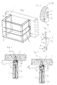
- the light well 2 consists of two lateral, vertical and mutually parallel walls 2a which have vertical contact surfaces 2b which rest on the outer surface of a wall 1.
- the reinforcement of the light well essentially consists of vertical round bars 5 and horizontal round bars 6.
- Two brackets 4 are provided on the two contact surfaces 2b of the light well 2, which bear against the wall 1, which have at least one hole or slot 4b for the use of a fastening bolt 3a Have nut 3b; the fastening bolt is anchored by means of a wall plug 3 inserted into the wall 1 drilled hole.
- the bracket 4 assumes an angled position ⁇ relative to the outer surface of the wall 1 because either the vertical part of the bracket 4 has a triangular or trapezoidal cross section (FIG.
- bracket 4 On the outer surface of the two side walls 2a of the light well 2, a recess 2c is provided in the area of the bracket 4, which preferably has a prismatic shape with a triangular cross section and allows easy access to the area of the holes or the slots 4b so as to enable the corresponding ones To be able to drill holes in the wall 1, insert the wall dowels 3 and then attach the fastening bolts 3a and the corresponding threaded nuts 3b, always unimpeded along the axis A of said elements 3, 3a, 3b which are aligned with the axis of the holes or the slots, 4b are aligned, to be able to work.
- the round rods 5, 6, which form the basic reinforcement of the light well 2 are anchored to the brackets 4 by being inserted into corresponding bores 4c, 4d on the spread legs 4a of the bracket 4.
- the invention does not rule out that the round rods 5, 6 of the reinforcement of the light well 2 are laid in a different shape and are also attached or anchored to the brackets 4 in a different way and that the spread legs 4a assume a different shape and orientation, the Bracket 4, however, always assume their angled position with respect to the surface of wall 1 or with respect to support surface 2b of the light well.
- 4 cores are attached to the holes or slots 4b of the bracket 4, which cores correspond in shape to those of the prismatic recess 2b for free access.
- appropriate drilling templates can also be used to carry out the holes on the wall 1 for the purpose of attaching the wall dowels 3, which facilitate drilling, taking into account the required angling of the axis A of the borehole.
Landscapes
- Engineering & Computer Science (AREA)
- Architecture (AREA)
- Civil Engineering (AREA)
- Structural Engineering (AREA)
- Joining Of Building Structures In Genera (AREA)
- Golf Clubs (AREA)
- Rod-Shaped Construction Members (AREA)
- Diaphragms For Electromechanical Transducers (AREA)
- Nitrogen And Oxygen Or Sulfur-Condensed Heterocyclic Ring Systems (AREA)
Abstract
Description
Es sind Lichtschächte welche mit Befestigungselementen und/oder mit Einhängelementen versehen sind bekannt, insbesondere in der DE-GM 75 34 695 ist ein Lichtschacht beschrieben welcher an den beiden Oberflächen welche mit der Außenfläche der Mauer an welcher der Lichtschacht angebracht ist, mit einer Ausnehmung versehen ist innerhalb welcher an einem vorstehendem Gewindeteil eines Rundstabes mittels Schraubenmutter ein Einhängbügel befestigt ist dessen Ende mittels einem Schraubenbolzen an entsprechender Stelle mittels Mauerdübel an der Mauer befestigt ist. Dieses System bringt den Nachteil mit sich, dass die Mauerdübel vorher an der Mauer in relativ präziser Position vorgesehen werden müssen und dass, nach erfolgtem Einhängen, während der Befestigungsfase sich die Befestigungselemente nicht in einer, für die üblichen Werkzeuge, leicht zugänglichen Position befinden.
In der DE 29 06 419 ist ein Verankerungssystem zwischen dem vorgefertigten Mauerteil einer Fensteröffnung und eines Lichtschachtes gezeigt; dieses System sieht die Verankerung von Einhängelementen mit einer einfachen oder mehrfachen Öse, beziehungsweise Profile mit Schlitzen für Schaftschrauben, am vorgefertigtem Teil der Fensteröffnung und Schaftschrauben oder Elemente mit vorstehenden Einhängeelementen an den Lichtschächten, vor.
Dieses System ermöglicht das Einhängen gegebenenfalls ohne den Einsatz von Werkzeugen, es setzt jedoch die vorherige Verankerung der Einhängelemente sei es am tragenden Teil als auch am eingehängten Teil vor, ohne beim Einhängen ein Verändern der Position des Luftschachtes zu ermöglichen, gegebenenfalls ist nur eine vorgegebene Veränderung in der Höhe möglich wenn am tragenden Teil Verankerungselemente mit mehrfachen Ösen vorgesehen sind.
Auch in der CH 688 828 A5 ist ein Verankerungssystem gezeigt welches eine genaue vorherige Positionierung der spezifischen Verankerungselemente an der tragenden Mauer und entsprechende vorstehende Einhängelemente am Lichtschacht, vorsieht. Auch dieses System ermöglicht nicht eine nachträgliche Einstellung oder Veränderung der Einhängeposition.
Die Erfindung wird anschließend anhand eines, in der beigelegten Zeichnung schematisch dargestellten, vorzuziehenden erfindungsgemäßen Ausführungsbeispieles eines, an einer Mauer befestigbaren, Lichtschachtes näher erklärt; die Zeichnung erfüllt dabei rein erklärenden, nicht begrenzenden Zweck.
Der Bügel 4 nimmt gegenüber der Außenfläche der Mauer 1 eine um einen Winkel α angewinkelte Position ein weil entweder der vertikale Teil des Bügels 4 dreieckigen oder trapezförmigen Querschnitt hat (Fig. 4) oder weil dieser Teil des Bügels nur mit seiner äußeren vertikalen Kante (Fig. 5) an der Mauer 1 anliegt. An der Außenfläche der beiden seitlichen Wände 2a des Lichtschachtes 2 ist im Bereich des Bügels 4 je eine Ausnehmung 2c vorgesehen welche vorzugsweise prismatische Form mit dreieckigem Querschnitt hat und einen leichten Zugang zum Bereich der Löcher, bzw. der Schlitze, 4b ermöglicht um so die entsprechenden Bohrungen an der Mauer 1, das Einsetzen der Mauerdübel 3 und das folgende Anbringen der Befestigungsbolzen 3a und der entsprechenden Gewindemuttern 3b durchführen zu können und dabei immer unbehindert längs der Achse A besagter Elemente 3, 3a, 3b welche mit der Achse der Löcher, bzw. der Schlitze, 4b fluchten, arbeiten zu können.
Die Rundstäbe 5, 6 welche die Grundarmierung des Lichtschachtes 2 bilden sind an den Bügeln 4 verankert indem sie in entsprechende Bohrungen 4c, 4d an den gespreizten Schenkeln 4a des Bügels 4 eingesteckt sind.
Die Erfindung schließt nicht aus, dass die Rundstäbe 5, 6 der Armierung des Lichtschachtes 2 in anderer Form verlegt sind und auch auf andere Art an den Bügeln 4 befestigt oder verankert sind und dass die gespreizten Schenkel 4a eine andere Form und Ausrichtung einnehmen, wobei die Bügel 4 aber immer ihre angewinkelte Position gegenüber der Oberfläche der Mauer 1, bzw. gegenüber der Auflagefläche 2b des Lichtschachtes, einnehmen.
Vorteilhafterweise werden während der Produktionsfase des erfindungsgemäßen Lichtschachtes an den Löchern oder Schlitzen 4b der Bügel 4 Kerne befestigt welche in Ihrer Form jener der prismatischen Ausnehmung 2b für den freien Zugang entsprechen.
Natürlich können für die Durchführung der Bohrungen an der Mauer 1 zwecks Anbringung der Mauerdübel 3 auch entsprechende Bohrschablonen verwendet werden welche das Bohren unter Berücksichtigung der erforderlichen Anwinkelung der Achse A des Bohrloches erleichtern.
Claims (5)
- Verankerungssystem für Lichtschächte (2) oder andere Fertigteile aus Beton welche an einer wesentlich vertikalen Mauer (1) zu befestigen sind, dadurch gekennzeichnet, dass an den Auflageflächen (2b) des Lichtschachtes (2) oder anderer Fertigteile Befestigungsbügel (4) vorgesehen sind welche jeweils ein Loch oder einen Schlitz (4b) für das Einsetzen einer in einem, in der Mauer (1) vorgesehenen, Mauerdübel (3) eingeschraubten Befestigungsschraube (3a) aufweisen und welche durch Anliegen mit ihrer vertikalen äußeren Kante an der Außenfläche der Mauer(1) oder wegen ihres dreieckigen Querschnittes am vertikalen Bügelteil, zur Mauer angewinkelt (α) sind.
- Verankerungssystem gemäß Anspruch 1, dadurch gekennzeichnet, dass der Bereich des mit mindestens einem Loch oder einem Schlitz (4b) ausgestatteten Bügels (4) durch eine Ausnehmung (2c), welche an entsprechender Stelle an der jeweiligen Seitenwand (2a) des Lichtschachtes (2) oder eines anderen Fertigteiles vorgesehen ist, seitlich zugänglich ist, wobei diese Ausnehmung vorzugsweise prismatische Form aufweist und derartige Form und Ausmaße hat, dass der freie Zugang in diesem Bereich gemäß einer, in Bezug auf die Oberfläche der Mauer (1) angewinkelte, der Achse des Mauerdübels (3) und der Befestigungsschraube (3a) entsprechende, Achse (A) gesichert ist.
- Verankerungssystem gemäß Anspruch 1, dadurch gekennzeichnet, dass der Bügel (4) zwei gespreizte Schenkel (4a) aufweist welche mindestens teilweise im Beton eingegossen sind und Bohrungen (4c, 4d) aufweisen durch welche Rundstäbe (5) gesteckt sind, bzw. an welchen Rundstäbe oder Stangen (6) eingehängt sind welche die Armierung des an einer Mauer (1) zu befestigenden Lichtschachtes (2) oder eines ähnlichen Fertigteiles aus Beton bilden.
- Verankerungssystem gemäß Anspruch 1, dadurch gekennzeichnet, dass der Bügel (4) selbst mit den Schenkeln (4a) eine Schalenform hat oder Wände aufweist welche nach außen seitlich in der Seitenwand (2a) des Lichtschachtes (2) die Ausnehmung (2c) für den Zugang bilden.
- Verankerungssystem gemäß Anspruch 1, dadurch gekennzeichnet, dass die Löcher oder Schlitze (4b) am Bügel (4), während des Schüttens des Betons des Lichtschachtes (2), für die Befestigung von Kernen welche die in den Seitenwänden (2a) des Lichtschachtes eingeformten Ausnehmungen (2c) bestimmen.
Applications Claiming Priority (2)
| Application Number | Priority Date | Filing Date | Title |
|---|---|---|---|
| ITBZ20020022 | 2002-05-15 | ||
| IT2002BZ000022A ITBZ20020022A1 (it) | 2002-05-15 | 2002-05-15 | Sistema di ancoraggio per bocche di lupo. |
Publications (2)
| Publication Number | Publication Date |
|---|---|
| EP1362969A1 true EP1362969A1 (de) | 2003-11-19 |
| EP1362969B1 EP1362969B1 (de) | 2008-08-27 |
Family
ID=29266920
Family Applications (1)
| Application Number | Title | Priority Date | Filing Date |
|---|---|---|---|
| EP03010358A Expired - Lifetime EP1362969B1 (de) | 2002-05-15 | 2003-05-08 | Lichtschacht aus armiertem Beton |
Country Status (4)
| Country | Link |
|---|---|
| EP (1) | EP1362969B1 (de) |
| AT (1) | ATE406490T1 (de) |
| DE (1) | DE50310397D1 (de) |
| IT (1) | ITBZ20020022A1 (de) |
Families Citing this family (1)
| Publication number | Priority date | Publication date | Assignee | Title |
|---|---|---|---|---|
| CN110512831B (zh) * | 2019-09-02 | 2021-03-23 | 李良发 | 一种民用建筑物公共通风管道的施工方法 |
Citations (4)
| Publication number | Priority date | Publication date | Assignee | Title |
|---|---|---|---|---|
| DE6939021U (de) * | 1969-10-06 | 1970-03-19 | Bruno Heibges | Befestigungseinrichtung fuer betonfertigteile |
| DE7534695U (de) * | 1975-10-31 | 1976-03-11 | M. Meisinger Kg, 8890 Aichach | Lichtschacht-fertigteil, insbesondere aus beton |
| DE2906419A1 (de) * | 1979-02-20 | 1980-08-28 | Karl Stoecker | Fensterrahmengewaende, vorzugs- weise fuer kellerfenster mit montier- barem lichtschacht |
| CH688828A5 (de) * | 1994-12-23 | 1998-04-15 | Poly Bauelemente Ag | Vorrichtung zur Montage eines Lichtschachtes an einer Aussenwand eines Gebäudes. |
-
2002
- 2002-05-15 IT IT2002BZ000022A patent/ITBZ20020022A1/it unknown
-
2003
- 2003-05-08 AT AT03010358T patent/ATE406490T1/de not_active IP Right Cessation
- 2003-05-08 EP EP03010358A patent/EP1362969B1/de not_active Expired - Lifetime
- 2003-05-08 DE DE50310397T patent/DE50310397D1/de not_active Expired - Lifetime
Patent Citations (4)
| Publication number | Priority date | Publication date | Assignee | Title |
|---|---|---|---|---|
| DE6939021U (de) * | 1969-10-06 | 1970-03-19 | Bruno Heibges | Befestigungseinrichtung fuer betonfertigteile |
| DE7534695U (de) * | 1975-10-31 | 1976-03-11 | M. Meisinger Kg, 8890 Aichach | Lichtschacht-fertigteil, insbesondere aus beton |
| DE2906419A1 (de) * | 1979-02-20 | 1980-08-28 | Karl Stoecker | Fensterrahmengewaende, vorzugs- weise fuer kellerfenster mit montier- barem lichtschacht |
| CH688828A5 (de) * | 1994-12-23 | 1998-04-15 | Poly Bauelemente Ag | Vorrichtung zur Montage eines Lichtschachtes an einer Aussenwand eines Gebäudes. |
Also Published As
| Publication number | Publication date |
|---|---|
| DE50310397D1 (de) | 2008-10-09 |
| ITBZ20020022A1 (it) | 2003-11-17 |
| EP1362969B1 (de) | 2008-08-27 |
| ATE406490T1 (de) | 2008-09-15 |
Similar Documents
| Publication | Publication Date | Title |
|---|---|---|
| DE2243102A1 (de) | Tragstuetze fuer aufgestaenderte fussboeden | |
| EP1362969B1 (de) | Lichtschacht aus armiertem Beton | |
| EP0201768A2 (de) | Installationseinheit für Sanitärapparate | |
| DE20118269U1 (de) | Bausystem für Wege, Terrassen, Stufen, Brücken, Möbel o.dgl. Elemente zur Gestaltung von Gärten oder Parks | |
| EP1335077A1 (de) | Einrichtung zur Befestigung von Sanitärobjekten der wandhängenden Ausführung | |
| DE202005002790U1 (de) | Bausatz zur Verbindung von Trägerelementen | |
| DE102004061513B3 (de) | Treppengerüst für eine Böschung | |
| EP0345213A1 (de) | Geländerpfosten | |
| DE8901067U1 (de) | Hohlplattendübel | |
| DE2552736A1 (de) | Vorrichtung zur anbringung von teilen im betonbau | |
| DE10161426A1 (de) | Verankerung für verspannte Konstruktionen | |
| DE20215072U1 (de) | Absturzsicherung bei leicht geneigten Dächern und bei Flachdächern | |
| DE20008530U1 (de) | Distanzhalter für Betonhohlraumelemente | |
| DE102014113973A1 (de) | Fugenelement zur Abdichtung von Stoß- und/oder Eckfugen | |
| EP4148222A1 (de) | Einbausatz für eine zarge mit höhenverstell- und feststellvorrichtung | |
| DE102006013633B4 (de) | Verbindungselement und Montageset | |
| DE19622611A1 (de) | Befestigungsankeranordnung | |
| DE2907345A1 (de) | Haustuervordach | |
| DE2023618A1 (de) | Verankerung zur freihängenden Befestigung vorgefertigter Wand- oder Fassadenplatten | |
| DE9016348U1 (de) | Einbauhilfe für Steigeisen | |
| DE102018130234A1 (de) | Montageset zur Verankerung eines Holzbauteils an einem Gebäudeabschnitt | |
| AT519309B1 (de) | Befestigungswinkel für deckenrandabschalungen | |
| DE29609963U1 (de) | Befestigungsankeranordnung | |
| DE9316354U1 (de) | Einhängevorrichtung, insbesondere für Arbeitsbühnen an Gebäudewandungen | |
| DE19503813C1 (de) | Fixierungselement für einen Mauerdübel |
Legal Events
| Date | Code | Title | Description |
|---|---|---|---|
| PUAI | Public reference made under article 153(3) epc to a published international application that has entered the european phase |
Free format text: ORIGINAL CODE: 0009012 |
|
| AK | Designated contracting states |
Kind code of ref document: A1 Designated state(s): AT BE BG CH CY CZ DE DK EE ES FI FR GB GR HU IE IT LI LU MC NL PT RO SE SI SK TR |
|
| AX | Request for extension of the european patent |
Extension state: AL LT LV MK |
|
| 17P | Request for examination filed |
Effective date: 20040428 |
|
| AKX | Designation fees paid |
Designated state(s): AT CH DE ES FR LI |
|
| 17Q | First examination report despatched |
Effective date: 20061123 |
|
| 17Q | First examination report despatched |
Effective date: 20061123 |
|
| GRAP | Despatch of communication of intention to grant a patent |
Free format text: ORIGINAL CODE: EPIDOSNIGR1 |
|
| RTI1 | Title (correction) |
Free format text: REINFORCED-CONCRETE LIGHT-SHAFT |
|
| GRAS | Grant fee paid |
Free format text: ORIGINAL CODE: EPIDOSNIGR3 |
|
| GRAA | (expected) grant |
Free format text: ORIGINAL CODE: 0009210 |
|
| AK | Designated contracting states |
Kind code of ref document: B1 Designated state(s): AT CH DE ES FR LI |
|
| REG | Reference to a national code |
Ref country code: CH Ref legal event code: EP |
|
| REG | Reference to a national code |
Ref country code: CH Ref legal event code: NV Representative=s name: E. BLUM & CO. AG PATENT- UND MARKENANWAELTE VSP |
|
| REF | Corresponds to: |
Ref document number: 50310397 Country of ref document: DE Date of ref document: 20081009 Kind code of ref document: P |
|
| PG25 | Lapsed in a contracting state [announced via postgrant information from national office to epo] |
Ref country code: ES Free format text: LAPSE BECAUSE OF FAILURE TO SUBMIT A TRANSLATION OF THE DESCRIPTION OR TO PAY THE FEE WITHIN THE PRESCRIBED TIME-LIMIT Effective date: 20081208 |
|
| PLBE | No opposition filed within time limit |
Free format text: ORIGINAL CODE: 0009261 |
|
| STAA | Information on the status of an ep patent application or granted ep patent |
Free format text: STATUS: NO OPPOSITION FILED WITHIN TIME LIMIT |
|
| 26N | No opposition filed |
Effective date: 20090528 |
|
| REG | Reference to a national code |
Ref country code: FR Ref legal event code: ST Effective date: 20100129 |
|
| PG25 | Lapsed in a contracting state [announced via postgrant information from national office to epo] |
Ref country code: FR Free format text: LAPSE BECAUSE OF NON-PAYMENT OF DUE FEES Effective date: 20090602 |
|
| PGFP | Annual fee paid to national office [announced via postgrant information from national office to epo] |
Ref country code: AT Payment date: 20100531 Year of fee payment: 8 |
|
| PGFP | Annual fee paid to national office [announced via postgrant information from national office to epo] |
Ref country code: CH Payment date: 20100608 Year of fee payment: 8 |
|
| PGFP | Annual fee paid to national office [announced via postgrant information from national office to epo] |
Ref country code: DE Payment date: 20100630 Year of fee payment: 8 |
|
| REG | Reference to a national code |
Ref country code: CH Ref legal event code: PL |
|
| PG25 | Lapsed in a contracting state [announced via postgrant information from national office to epo] |
Ref country code: LI Free format text: LAPSE BECAUSE OF NON-PAYMENT OF DUE FEES Effective date: 20110531 Ref country code: CH Free format text: LAPSE BECAUSE OF NON-PAYMENT OF DUE FEES Effective date: 20110531 |
|
| REG | Reference to a national code |
Ref country code: AT Ref legal event code: MM01 Ref document number: 406490 Country of ref document: AT Kind code of ref document: T Effective date: 20110508 |
|
| PG25 | Lapsed in a contracting state [announced via postgrant information from national office to epo] |
Ref country code: AT Free format text: LAPSE BECAUSE OF NON-PAYMENT OF DUE FEES Effective date: 20110508 |
|
| REG | Reference to a national code |
Ref country code: DE Ref legal event code: R119 Ref document number: 50310397 Country of ref document: DE Effective date: 20111201 |
|
| PG25 | Lapsed in a contracting state [announced via postgrant information from national office to epo] |
Ref country code: DE Free format text: LAPSE BECAUSE OF NON-PAYMENT OF DUE FEES Effective date: 20111201 |