EP1362811A2 - Einrichtung zum Einstellen eines Bogenniederhalters - Google Patents
Einrichtung zum Einstellen eines Bogenniederhalters Download PDFInfo
- Publication number
- EP1362811A2 EP1362811A2 EP03006269A EP03006269A EP1362811A2 EP 1362811 A2 EP1362811 A2 EP 1362811A2 EP 03006269 A EP03006269 A EP 03006269A EP 03006269 A EP03006269 A EP 03006269A EP 1362811 A2 EP1362811 A2 EP 1362811A2
- Authority
- EP
- European Patent Office
- Prior art keywords
- feed table
- sheet
- marks
- gear
- distance
- Prior art date
- Legal status (The legal status is an assumption and is not a legal conclusion. Google has not performed a legal analysis and makes no representation as to the accuracy of the status listed.)
- Granted
Links
Images
Classifications
-
- B—PERFORMING OPERATIONS; TRANSPORTING
- B65—CONVEYING; PACKING; STORING; HANDLING THIN OR FILAMENTARY MATERIAL
- B65H—HANDLING THIN OR FILAMENTARY MATERIAL, e.g. SHEETS, WEBS, CABLES
- B65H9/00—Registering, e.g. orientating, articles; Devices therefor
- B65H9/10—Pusher and like movable registers; Pusher or gripper devices which move articles into registered position
-
- B—PERFORMING OPERATIONS; TRANSPORTING
- B65—CONVEYING; PACKING; STORING; HANDLING THIN OR FILAMENTARY MATERIAL
- B65H—HANDLING THIN OR FILAMENTARY MATERIAL, e.g. SHEETS, WEBS, CABLES
- B65H2403/00—Power transmission; Driving means
- B65H2403/50—Driving mechanisms
- B65H2403/51—Cam mechanisms
- B65H2403/514—Cam mechanisms involving eccentric
-
- B—PERFORMING OPERATIONS; TRANSPORTING
- B65—CONVEYING; PACKING; STORING; HANDLING THIN OR FILAMENTARY MATERIAL
- B65H—HANDLING THIN OR FILAMENTARY MATERIAL, e.g. SHEETS, WEBS, CABLES
- B65H2511/00—Dimensions; Position; Numbers; Identification; Occurrences
- B65H2511/10—Size; Dimensions
- B65H2511/15—Height, e.g. of stack
-
- B—PERFORMING OPERATIONS; TRANSPORTING
- B65—CONVEYING; PACKING; STORING; HANDLING THIN OR FILAMENTARY MATERIAL
- B65H—HANDLING THIN OR FILAMENTARY MATERIAL, e.g. SHEETS, WEBS, CABLES
- B65H2515/00—Physical entities not provided for in groups B65H2511/00 or B65H2513/00
- B65H2515/81—Rigidity; Stiffness; Elasticity
Definitions
- the invention relates to a device for adjusting the bow hold of a side pull mark on the sheet material to be processed and conveyed onto a feed table in a printing press.
- a hold-down device is provided in the side draw mark whose distance from the feed table must be adjusted to the material thickness of the sheet to be processed.
- a manually operated adjusting device is provided.
- the disadvantage is that the adjusting device due to space conditions at the feed table bad accessible and to operate at a standstill of the printing press, which is to increase the setup time leads. In addition, it comes to incorrect settings, which lead to waste paper.
- the object of the invention is to provide a device for adjusting the sheet hold-down which increases the productivity of the press.
- the object is achieved by a device according to the features of the claim 1 solved.
- the solution according to the invention makes it possible to achieve the motor adaptation known per se the distance of the cover marks to the feed table for adaptation to the material thickness the processing for reaching bow with the adjustment of the side pull mark Associated bow hold down to the material thickness. This can be incorrect settings of the bow hold down are avoided. In addition, the set-up time shortened and corrected the setting of the bow hold down during the machine run become.
- a feed table 1 are promoted to the bow in a transport direction 2, shown with a side pull mark 3.
- the side puller 3 is mounted transversely to the transport direction 2 displaceable in the feed table 1 and can be locked by means not shown in the feed table 1.
- a base body 4 is shown, in which a in the double arrow direction 5 by means not shown displaceable in the power stroke pulling rail 6 is arranged.
- the surface of the drawing rail 6 forms a plane with the surface of the feed table 1.
- the puller rail 6 correspond to a rigidly connected to the base 4 side stop 7 and a sheet holder 8.
- the sheet hold-down 8 is pivotally mounted in a connected to the base 4 second frame point.
- an investment mark 10 is also shown.
- the Anlegmarken 10 are arranged distributed at intervals over the width of the feed table 1.
- Each of the Anlegmarken 10 consists of a deck 11 and a leading edge 12 and are pivotally mounted in a first frame point 13.
- the first frame point 13 may be formed, for example, as extending over the entire width of the feed table 1 brand wave.
- the pivoting of the Anlegmarken 10 to the first frame point 13 is effected by a drive gear 14, which is formed as a cam plate 15, cam roller 16, roller lever 17 and compression spring 18 existing cam mechanism 19.
- the roller lever 17 is mounted in the first frame point 13 and rotatably connected to the Anlegmarken 10.
- the Anlegmarken 10 are assigned in their position on the feed table 1 this so that the deck marks 11 are positioned at a distance s 1 to the feed table 1. This distance s 1 is adapted to the thickness of the material to be processed by the Anlegmarken 10 are moved perpendicular to the feed table 1.
- the first Gestellpunke 13 are raised or lowered by a first actuating gear 20. If the first frame points 13 are arranged, for example, on a brand shaft extending over the width of the feed table 1, then in each case a first setting gear 20 is provided on both sides of the brand shaft.
- the actuating gear 20 are formed in the embodiment as a ram cam 21.
- plunger cam shaft 23 With a mounted in a third frame point 22 plunger cam shaft 23 is a cam roller 24 in operative connection, which is mounted in a plunger 25. At the first frame point 13, the plunger 25 engages. The plunger 25 is guided in a straight guide 26 and held by a plunger 25 acting compression spring 27, the cam roller 24 in engagement with the plunger cam shaft 23.
- the plunger cam shaft 23 can be rotated by a drive, not shown, clockwise and counter to it. From the ram camshaft 23, two second actuating gear 28 are driven, wherein in each case a second actuating gear 28 is assigned to one of the usually two provided in a printing press side pull marks 3.
- a second actuating gear 28 consists of a drive member 29, a coupling 30 and an output member 31.
- the drive member 29 is formed as a ternary member and mounted in a fourth frame point 32 which is arranged on the base body 4 of the side pull 3.
- One end of the drive member 29 is formed as a fork 33 and engages over the plunger cam shaft 23, while the other is connected via a first ball joint 34 with the coupling 30, which acts on the output member 31 by means of a second ball joint 35.
- the output member 31 is mounted in the second frame point 9, which is also connected to the base body 4, together with the sheet hold-8.
- the output member 31 and the sheet suppressor 8 are rotatably connected to each other, so that the sheet suppressor 8 is positioned at a distance s 2 to the drawing rail 6 and thus to the feed table 1.
- the ram camshaft 23 is rotated via the drive, not shown.
- the first frame points 13 are raised on the plunger 25, whereby the Anlegmarken 10 are moved perpendicular to the feed table 1 and so the deck marks 11 are raised.
- the fork 33 of the drive member 29 is raised at the same time and so the first ball joint 34 is lowered with the coupling 30.
- the output member 31 is lowered so that the sheet hold-down 8 is raised and thus increases its distance s 2 to the feed table 1.
- the distance s 2 track so that the distances s 1 and s 2 remain the same.
Landscapes
- Registering Or Overturning Sheets (AREA)
- Sheets, Magazines, And Separation Thereof (AREA)
Abstract
Description
Nach dem Ausrichten des an den Anlegmarken angelegten Bogens nach der Vorderkante wird der Bogen durch eine Seitenziehmarke nach der Seitenkante ausgerichtet. Um zu gewährleisten, dass der auszurichtende Bogen auch sicher von der Zieheinrichtung erfasst und damit ordnungsgemäß nach der Seitenkante ausgerichtet wird, ist in der Seitenziehmarke ein Niederhalter vorgesehen, dessen Abstand zum Anlegtisch der Materialstärke der zur Verarbeitung gelangenden Bogen angepasst werden muss. Dazu ist eine manuell zu betätigende Stelleinrichtung vorgesehen.
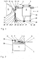
- Fig. 1
- die Einrichtung in einer schematischen Seitenansicht,
- Fig. 2
- eine Ansicht der Einrichtung nach Fig. 1 in Richtung A gesehen.
In einer Position am Anlegtisch 1 ist weiterhin eine Anlegmarke 10 gezeigt. Die Anlegmarken 10 sind in Abständen zueinander über die Breite des Anlegtischs 1 verteilt angeordnet. Jede der Anlegmarken 10 besteht aus einer Deckmarke 11 und einer Vordermarke 12 und sind in einem ersten Gestellpunkt 13 schwenkbar gelagert. Der erste Gestellpunkt 13 kann z.B. als sich über die gesamte Breite des Anlegtischs 1 erstreckende Markenwelle ausgebildet sein. Das Schwenken der Anlegmarken 10 um den ersten Gestellpunkt 13 erfolgt durch ein Antriebsgetriebe 14, das als aus Kurvenscheibe 15, Kurvenrolle 16, Rollenhebel 17 und Druckfeder 18 bestehendes Kurvengetriebe 19 ausgebildet ist. Der Rollenhebel 17 ist im ersten Gestellpunkt 13 gelagert und mit den Anlegmarken 10 drehfest verbunden. Die Anlegmarken 10 sind in ihrer Position am Anlegtisch 1 diesem so zugeordnet, dass die Deckmarken 11 in einem Abstand s1 zum Anlegtisch 1 positioniert sind. Dieser Abstand s1 wird der Stärke des zur Verarbeitung gelangenden Materials angepasst, indem die Anlegmarken 10 senkrecht zum Anlegtisch 1 verschoben werden. Dazu werden die ersten Gestellpunke 13 durch ein erstes Stellgetriebe 20 angehoben oder abgesenkt. Sind die ersten Gestellpunkte 13 z.B. auf einer sich über die Breite des Anlegtischs 1 erstreckenden Markenwelle angeordnet, so ist an beiden Seiten der Markenwelle jeweils ein erstes Stellgetriebe 20 vorgesehen.
Die Stellgetriebe 20 sind im Ausführungsbeispiel als Stößelkurvengetriebe 21 ausgebildet. Mit einer in einem dritten Gestellpunkt 22 gelagerten Stößelkurvenwelle 23 steht eine Kurvenrolle 24 in Wirkverbindung, die in einem Stößel 25 gelagert ist. Am ersten Gestellpunkt 13 greift der Stößel 25 an. Der Stößel 25 wird in einer Geradführung 26 geführt und durch eine Stößel 25 angreifende Druckfeder 27 die Kurvenrolle 24 in Eingriff mit der Stößelkurvenwelle 23 gehalten. Die Stößelkurvenwelle 23 kann durch einen nicht dargestellten Antrieb im Uhrzeigersinn und entgegen dazu verdreht werden.
Von der Stößelkurvenwelle 23 werden zwei zweite Stellgetriebe 28 angetrieben, wobei jeweils ein zweites Stellgetriebe 28 einer der üblicherweise zwei in einer Druckmaschine vorgesehenen Seitenziehmarken 3 zugeordnet ist. Ein zweites Stellgetriebe 28 besteht jeweils aus einem Antriebsglied 29, einer Koppel 30 und einem Abtriebglied 31. Das Antriebsglied 29 ist als ternäres Glied ausgebildet und in einem vierten Gestellpunkt 32 gelagert, der am Grundkörper 4 der Seitenziehmarke 3 angeordnet ist. Das eine Ende des Antriebsgliedes 29 ist als Gabel 33 ausgebildet und übergreift die Stößelkurvenwelle 23, während das andere über ein erstes Kugelgelenk 34 mit der Koppel 30 verbunden ist, die mittels eines zweiten Kugelgelenks 35 am Abtriebsglied 31 angreift. Das Abtriebsglied 31 ist im zweiten Gestellpunkt 9, der ebenfalls mit dem Grundkörper 4 verbunden ist, zusammen mit dem Bogenniederhalter 8 gelagert. Das Abtriebsglied 31 und der Bogenniederhalter 8 sind drehfest miteinander verbunden, so dass der Bogenniederhalter 8 in einem Abstands s2 zur Ziehschiene 6 und damit zum Anlegtisch 1 positioniert ist. Der Abstand s2 des Bogenniederhalters 8 zum Anlegtisch 1 wird, wie der Abstand s1 der Deckmarken 11 zum Anlegtisch, der Stärke des zur Verarbeitung gelangenden Bedruckstoffs angepasst, wobei der Abstand s1 gleich dem Abstand s2 ist.
Soll der Abstand s1 vergrößert werden, wird über den nicht dargestellten Antrieb die Stößelkurvenwelle 23 verdreht. Damit werden über die Stößel 25 die ersten Gestellpunkte 13 angehoben, wodurch die Anlegmarken 10 senkrecht zum Anlegtisch 1 verschoben und so die Deckmarken 11 angehoben werden. Durch die Stellbewegung der Stößelkurvenwelle 23 wird gleichzeitig die Gabel 33 des Antriebsgliedes 29 angehoben und so das erste Kugelgelenk 34 mit der Koppel 30 abgesenkt. Durch das Absenken der Koppel 30 wird das Abtriebsglied 31 abgesenkt, damit der Bogenniederhalter 8 angehoben und so sein Abstand s2 zum Anlegtisch 1 vergrößert. Durch eine entsprechende Wahl der geometrischen Abmessungen der Glieder des zweiten Stellgetriebes 28 ist es möglich, bei einer Veränderung des Abstandes s1 den Abstand s2 so nachzuführen, dass die Abstände s1 und s2 gleich bleiben.
- 1
- Anlegtisch
- 2
- Transportrichtung
- 3
- Seitenziehmarke
- 4
- Grundkörper
- 5
- Doppelpfeilrichtung
- 6
- Ziehschiene
- 7
- Seitenanschlag
- 8
- Bogenniederhalter
- 9
- zweiter Gestellpunkt
- 10
- Anlegmarke
- 11
- Deckmarke
- 12
- Vordermarke
- 13
- erster Gestellpunkt
- 14
- Antriebsgetriebe
- 15
- Kurvenscheibe
- 16
- Kurvenrolle
- 17
- Rollenhebel
- 18
- Druckfeder
- 19
- Kurvengetriebe
- 20
- erstes Stellgetriebe
- 21
- Stößelkurvengetriebe
- 22
- dritter Gestellpunkt
- 23
- Stößelkurvenwelle
- 24
- Kurvenrolle
- 25
- Stößel
- 26
- Geradführung
- 27
- Druckfeder
- 28
- zweites Stellgetriebe
- 29
- Ahtriebsglied
- 30
- Koppel
- 31
- Abtriebsglied
- 32
- vierter Gestellpunkt
- 33
- Gabel
- 34
- erstes Kugelgelenk
- 35
- zweites Kugelgelenk
- s1
- Abstand der Deckmarken
- s2
- Abstand des Bogenniederhalters
Claims (5)
- Einrichtung zum Einstellen des Bogenniederhalters (8) einer Seitenziehmarke (3) auf das zur Verarbeitung gelangende, auf einen Anlegtisch (1) geförderte Bogenmaterial in einer Druckmaschinemit aus einer Vordermarke (12) und einer Deckmarke (11) bestehenden, höhenverstellbaren Anlegmarken (10),die Anlegmarken (10) sind zum Verbringen aus einer Position zum Anlegtisch (1) in eine Position unter den Anlegtisch (1) schwenkbar in einem ersten Gestellpunkt (13) gelagert,das Verschwenken der Anlegmarken (10) erfolgt mittels eines Antriebsgetriebes (14),die Höhenverstellung der Anlegmarken (10) zum Einstellen eines Abstandes (s1) der Deckmarken (11) zum Anlegtisch (1) erfolgt durch ein die ersten Gestellpunkte (13) in ihrer Höhenlage veränderndes erstes Stellgetriebe (20),mit dem ersten Stellgetriebe (20) ist ein aus einem Antriebsglied (29), einer Koppel (30) und einem Abtriebsglied (31) bestehendes zweites Stellgetriebe (28) verbunden,das Abtriebsglied (31) ist mit dem Bogenniederhalter (8) zum Nachführen eines Abstandes (s2) des Bogenniederhalters (8) zum Anlegtisch (1) dem Abstand (s1 verbunden.
- Einrichtung nach Anspruch 1,mit einem zweiten Gestellpunkt (9) und einem vierten Gestellpunkt (32) des zweiten Stellgetriebes (28), die der Seitenziehmarke (3) zugeordnet sind.
- Einrichtung nach Anspruch 1,mit einer verdrehbaren, dem ersten Stellgetriebe (20) zugeordneten Stößelkurvenwelle (23).
- Einrichtung nach Anspruch 1 und 3,mit einer Gabel (33), die mit dem Antriebsglied (29) verbunden ist und mit der Stößelkurvenwelle (23) in Wirkverbindung steht.
- Einrichtung nach Anspruch 1 und 4,mit der Gabel (33), die verschiebbar auf der Stößelkurvenwelle (23) geführt ist.
Applications Claiming Priority (2)
| Application Number | Priority Date | Filing Date | Title |
|---|---|---|---|
| DE10222055A DE10222055A1 (de) | 2002-05-17 | 2002-05-17 | Einrichtung zum Einstellen des Bogenniederhalters |
| DE10222055 | 2002-05-17 |
Publications (3)
| Publication Number | Publication Date |
|---|---|
| EP1362811A2 true EP1362811A2 (de) | 2003-11-19 |
| EP1362811A3 EP1362811A3 (de) | 2004-12-22 |
| EP1362811B1 EP1362811B1 (de) | 2006-05-31 |
Family
ID=29265349
Family Applications (1)
| Application Number | Title | Priority Date | Filing Date |
|---|---|---|---|
| EP03006269A Expired - Lifetime EP1362811B1 (de) | 2002-05-17 | 2003-03-21 | Einrichtung zum Einstellen eines Bogenniederhalters |
Country Status (2)
| Country | Link |
|---|---|
| EP (1) | EP1362811B1 (de) |
| DE (2) | DE10222055A1 (de) |
Cited By (1)
| Publication number | Priority date | Publication date | Assignee | Title |
|---|---|---|---|---|
| DE102009001190A1 (de) | 2009-02-26 | 2010-09-02 | Koenig & Bauer Aktiengesellschaft | Bogenverarbeitende Maschine mit einem Anlegetisch |
Families Citing this family (1)
| Publication number | Priority date | Publication date | Assignee | Title |
|---|---|---|---|---|
| DE102014201773A1 (de) | 2013-01-31 | 2014-07-31 | Koenig & Bauer Aktiengesellschaft | Leiteinrichtung |
Family Cites Families (6)
| Publication number | Priority date | Publication date | Assignee | Title |
|---|---|---|---|---|
| SE306326B (de) * | 1966-06-11 | 1968-11-25 | Planeta Veb Druckmasch Werke | |
| DD229096A1 (de) * | 1984-10-29 | 1985-10-30 | Polygraph Leipzig | Sicherheitseinrichtung an der anlegetrommel zur kontrolle der doppelbogenkontrollvorrichtung |
| DE3716085A1 (de) * | 1987-05-14 | 1988-12-01 | Roland Man Druckmasch | Bogenglaetteinrichtung fuer die seitenkante eines bogens |
| DE4239254C2 (de) * | 1992-11-21 | 2000-09-07 | Koenig & Bauer Ag | Einrichtung zum Einstellen der Anlegmarken |
| DE10047077B4 (de) * | 2000-09-22 | 2005-08-11 | Koenig & Bauer Ag | Vorrichtung zum seitlichen Ausrichten |
| DE10048314B4 (de) * | 2000-09-28 | 2005-09-08 | Koenig & Bauer Ag | Seitenziehvorrichtung |
-
2002
- 2002-05-17 DE DE10222055A patent/DE10222055A1/de not_active Withdrawn
-
2003
- 2003-03-21 DE DE50303545T patent/DE50303545D1/de not_active Expired - Lifetime
- 2003-03-21 EP EP03006269A patent/EP1362811B1/de not_active Expired - Lifetime
Cited By (2)
| Publication number | Priority date | Publication date | Assignee | Title |
|---|---|---|---|---|
| DE102009001190A1 (de) | 2009-02-26 | 2010-09-02 | Koenig & Bauer Aktiengesellschaft | Bogenverarbeitende Maschine mit einem Anlegetisch |
| DE102009001190B4 (de) | 2009-02-26 | 2023-11-09 | Koenig & Bauer Ag | Bogenverarbeitende Maschine mit einem Anlegetisch |
Also Published As
| Publication number | Publication date |
|---|---|
| DE10222055A1 (de) | 2003-11-27 |
| EP1362811A3 (de) | 2004-12-22 |
| EP1362811B1 (de) | 2006-05-31 |
| DE50303545D1 (de) | 2006-07-06 |
Similar Documents
| Publication | Publication Date | Title |
|---|---|---|
| WO2008028309A1 (de) | Registereinzugsvorrichtung | |
| DE102020111448B4 (de) | Vorrichtung zum Handhaben eines Stapels blattförmigen Guts | |
| DE69011250T2 (de) | Papierzufuhrvorrichtung. | |
| DD132652B1 (de) | Verfahren und einrichtung zum ausrichten von bogen | |
| EP0392454A2 (de) | Anlegevorrichtung | |
| DE3318144A1 (de) | Vorrichtung zur herstellung von matrizen fuer eine tiegelpresse | |
| DE3643915A1 (de) | Sauger in wendetrommeln von druckmaschinen | |
| WO2005110755B1 (de) | Verfahren zum zuführen einer druckform zu einem formzylinder einer druckmaschine, verfahren zur herstellung dieser druckform und vorrichtung zum seitlichen ausrichten und führen eines einem zylinder einer druckmaschine zuzuführenden aufzugs | |
| EP1362811B1 (de) | Einrichtung zum Einstellen eines Bogenniederhalters | |
| DE69713371T2 (de) | Vorrichtung zum miteinanderverbinden von flachen gegenständen | |
| EP0178399A2 (de) | Verfahren zum Ausrichten und Zuführen von Druckbögen an Druckmaschinen | |
| EP1726442B1 (de) | Flachbettdruckmaschine | |
| DE3150169A1 (de) | Vorrichtung zum seitlichen ausrichten von bogen in einer druckmaschine | |
| DD280296A1 (de) | Vorrichtung zum ausrichten von bogen nach der vorderkante | |
| DE3317084C2 (de) | ||
| EP1354833A2 (de) | Verfahren zum Ausrichten von Bogen nach der Seitenkante | |
| DE1786196A1 (de) | Verfahren und Vorrichtung zur Papierblatteinstellung bei Druckmaschinen | |
| DE10222057B4 (de) | Einrichtung zum Einstellen des Bogenniederhalters | |
| DE102009001190B4 (de) | Bogenverarbeitende Maschine mit einem Anlegetisch | |
| DD220005A1 (de) | Beschickungsvorrichtung fuer in fliesslinie angeordnete naehautomaten | |
| DE1761358A1 (de) | Vorrichtung an Druckmaschinen fuer das seitliche Ausrichten von Papierboegen | |
| DE10048314B4 (de) | Seitenziehvorrichtung | |
| DE19501798A1 (de) | Verfahren und Vorrichtung zum Ausrichten eines Bogens auf dem Anlegetisch einer Bogenrotationsdruckmaschine | |
| DE3417764A1 (de) | Zufuehreinrichtung fuer bogenverarbeitende maschinen, insbesondere druckmaschinen | |
| EP1537995A2 (de) | Verfahren zum Ausrichten von Bogen nach der Seitenkante |
Legal Events
| Date | Code | Title | Description |
|---|---|---|---|
| PUAI | Public reference made under article 153(3) epc to a published international application that has entered the european phase |
Free format text: ORIGINAL CODE: 0009012 |
|
| AK | Designated contracting states |
Kind code of ref document: A2 Designated state(s): AT BE BG CH CY CZ DE DK EE ES FI FR GB GR HU IE IT LI LU MC NL PT SE SI SK TR |
|
| AX | Request for extension of the european patent |
Extension state: AL LT LV MK RO |
|
| PUAL | Search report despatched |
Free format text: ORIGINAL CODE: 0009013 |
|
| AK | Designated contracting states |
Kind code of ref document: A3 Designated state(s): AT BE BG CH CY CZ DE DK EE ES FI FR GB GR HU IE IT LI LU MC NL PT SE SI SK TR |
|
| AX | Request for extension of the european patent |
Extension state: AL LT LV MK RO |
|
| 17P | Request for examination filed |
Effective date: 20041113 |
|
| 17Q | First examination report despatched |
Effective date: 20050624 |
|
| AKX | Designation fees paid |
Designated state(s): DE FR GB |
|
| GRAP | Despatch of communication of intention to grant a patent |
Free format text: ORIGINAL CODE: EPIDOSNIGR1 |
|
| GRAS | Grant fee paid |
Free format text: ORIGINAL CODE: EPIDOSNIGR3 |
|
| GRAA | (expected) grant |
Free format text: ORIGINAL CODE: 0009210 |
|
| AK | Designated contracting states |
Kind code of ref document: B1 Designated state(s): DE FR GB |
|
| REG | Reference to a national code |
Ref country code: GB Ref legal event code: FG4D Free format text: NOT ENGLISH |
|
| REF | Corresponds to: |
Ref document number: 50303545 Country of ref document: DE Date of ref document: 20060706 Kind code of ref document: P |
|
| GBT | Gb: translation of ep patent filed (gb section 77(6)(a)/1977) |
Effective date: 20060920 |
|
| ET | Fr: translation filed | ||
| PLBE | No opposition filed within time limit |
Free format text: ORIGINAL CODE: 0009261 |
|
| STAA | Information on the status of an ep patent application or granted ep patent |
Free format text: STATUS: NO OPPOSITION FILED WITHIN TIME LIMIT |
|
| 26N | No opposition filed |
Effective date: 20070301 |
|
| PGFP | Annual fee paid to national office [announced via postgrant information from national office to epo] |
Ref country code: FR Payment date: 20130408 Year of fee payment: 11 Ref country code: GB Payment date: 20130321 Year of fee payment: 11 |
|
| GBPC | Gb: european patent ceased through non-payment of renewal fee |
Effective date: 20140321 |
|
| REG | Reference to a national code |
Ref country code: FR Ref legal event code: ST Effective date: 20141128 |
|
| PG25 | Lapsed in a contracting state [announced via postgrant information from national office to epo] |
Ref country code: GB Free format text: LAPSE BECAUSE OF NON-PAYMENT OF DUE FEES Effective date: 20140321 Ref country code: FR Free format text: LAPSE BECAUSE OF NON-PAYMENT OF DUE FEES Effective date: 20140331 |
|
| REG | Reference to a national code |
Ref country code: DE Ref legal event code: R081 Ref document number: 50303545 Country of ref document: DE Owner name: KOENIG & BAUER AG, DE Free format text: FORMER OWNER: KOENIG & BAUER AKTIENGESELLSCHAFT, 97080 WUERZBURG, DE |
|
| PGFP | Annual fee paid to national office [announced via postgrant information from national office to epo] |
Ref country code: DE Payment date: 20180305 Year of fee payment: 16 |
|
| REG | Reference to a national code |
Ref country code: DE Ref legal event code: R119 Ref document number: 50303545 Country of ref document: DE |
|
| PG25 | Lapsed in a contracting state [announced via postgrant information from national office to epo] |
Ref country code: DE Free format text: LAPSE BECAUSE OF NON-PAYMENT OF DUE FEES Effective date: 20191001 |