EP1361019B1 - Führungsschiene - Google Patents
Führungsschiene Download PDFInfo
- Publication number
- EP1361019B1 EP1361019B1 EP03004547A EP03004547A EP1361019B1 EP 1361019 B1 EP1361019 B1 EP 1361019B1 EP 03004547 A EP03004547 A EP 03004547A EP 03004547 A EP03004547 A EP 03004547A EP 1361019 B1 EP1361019 B1 EP 1361019B1
- Authority
- EP
- European Patent Office
- Prior art keywords
- guide rail
- tool
- rail
- accordance
- machining tool
- Prior art date
- Legal status (The legal status is an assumption and is not a legal conclusion. Google has not performed a legal analysis and makes no representation as to the accuracy of the status listed.)
- Expired - Lifetime
Links
- 229910000831 Steel Inorganic materials 0.000 claims abstract description 4
- 239000010959 steel Substances 0.000 claims abstract description 4
- 238000003860 storage Methods 0.000 claims description 21
- 239000000463 material Substances 0.000 claims description 6
- 238000004804 winding Methods 0.000 claims description 5
- 238000005096 rolling process Methods 0.000 claims description 4
- 238000000034 method Methods 0.000 claims description 3
- 238000007650 screen-printing Methods 0.000 claims description 3
- 238000003754 machining Methods 0.000 claims 23
- 244000144992 flock Species 0.000 claims 1
- 239000007769 metal material Substances 0.000 claims 1
- 230000001681 protective effect Effects 0.000 claims 1
- 230000009466 transformation Effects 0.000 claims 1
- 238000012545 processing Methods 0.000 abstract description 45
- 239000002184 metal Substances 0.000 abstract description 2
- 230000008901 benefit Effects 0.000 description 5
- 238000013461 design Methods 0.000 description 4
- 239000011248 coating agent Substances 0.000 description 3
- 238000000576 coating method Methods 0.000 description 3
- 238000004049 embossing Methods 0.000 description 3
- 230000001419 dependent effect Effects 0.000 description 2
- 238000006073 displacement reaction Methods 0.000 description 2
- 238000004519 manufacturing process Methods 0.000 description 2
- 230000004308 accommodation Effects 0.000 description 1
- 230000009286 beneficial effect Effects 0.000 description 1
- 238000004140 cleaning Methods 0.000 description 1
- 238000010073 coating (rubber) Methods 0.000 description 1
- 238000010276 construction Methods 0.000 description 1
- 238000011109 contamination Methods 0.000 description 1
- 239000000428 dust Substances 0.000 description 1
- 238000007688 edging Methods 0.000 description 1
- 238000009408 flooring Methods 0.000 description 1
- 238000002360 preparation method Methods 0.000 description 1
- 230000000284 resting effect Effects 0.000 description 1
- 239000003351 stiffener Substances 0.000 description 1
- 239000004753 textile Substances 0.000 description 1
- 238000012549 training Methods 0.000 description 1
- 238000012546 transfer Methods 0.000 description 1
- 239000002023 wood Substances 0.000 description 1
Images


Classifications
-
- B—PERFORMING OPERATIONS; TRANSPORTING
- B23—MACHINE TOOLS; METAL-WORKING NOT OTHERWISE PROVIDED FOR
- B23Q—DETAILS, COMPONENTS, OR ACCESSORIES FOR MACHINE TOOLS, e.g. ARRANGEMENTS FOR COPYING OR CONTROLLING; MACHINE TOOLS IN GENERAL CHARACTERISED BY THE CONSTRUCTION OF PARTICULAR DETAILS OR COMPONENTS; COMBINATIONS OR ASSOCIATIONS OF METAL-WORKING MACHINES, NOT DIRECTED TO A PARTICULAR RESULT
- B23Q9/00—Arrangements for supporting or guiding portable metal-working machines or apparatus
- B23Q9/0014—Portable machines provided with or cooperating with guide means supported directly by the workpiece during action
- B23Q9/0042—Portable machines provided with or cooperating with guide means supported directly by the workpiece during action the guide means being fixed only on the workpiece
Definitions
- the invention relates to guide rails according to the preamble of claim 1, as z.
- guide rails for example, from US 4,463,644, for electric machines, especially for hand-held circular saws, jigsaws and routers, the top as a guide for the processing machine, in particular for a machine base plate, are formed and with their underside can be applied to a workpiece to be machined.
- This problem can be solved by moving the machine on the machine Guide rail encounter by working under relatively large Tilt angles the processing machine and thus the tool, e.g. the saw blade of a circular saw, offset outwards and on for these cases additionally provided guidance is guided.
- the tool e.g. the saw blade of a circular saw
- One Such implementation of the machine but is annoying in practice and leads in addition to the location where the tool, e.g. the saw blade, immersed in the surface of the workpiece, not for all angles of inclination the tool is the same.
- the object of the invention is to deal with guide rails of to simplify and simplify the aforementioned type for the user, in particular, the handling of the guide rail both with regard to transport and storage as well as with regard to Use with pivotable processing machines such. Circular saws and jigsaws improved even at high angles of inclination shall be.
- the rail is at least partially flexibly configured to be of an elongated use configuration in a compact transport and / or storage combination can be transferred.
- the flexible or movable rail can be rolled up or winding are brought into the transport configuration, so that a closed ring shape with e.g. circular, elliptical or oval Gestalt arises.
- the maximum dimension of the rail will be on this Way at least halved.
- the flexibility of the rail is preferably achieved by the Rail compared to the known rigid guide rails, the have a thickness of the order of 5 mm to 15 mm, very is performed thin.
- the rail can be designed as a sheet metal rail and, for example, a sheet material having a thickness in the range from 0.3 to 0.5 mm.
- a preferred material is steel sheet.
- the thickness of the invention Guide rail depending on a specific characteristic Dimension of the machine tools used in connection with the rail selected.
- the thickness reduction of the guide rail according to the invention is also advantageous when the guide rail in conjunction is used with pivotable processing machines.
- At least the one Edge region of the rail, the pivoting tool in operation the processing machine is facing is designed so thin, that the rail even with in the plane of its top extending tool pivot axis and with minimal working distance from the edge of the Rail or positioned by a machine-fixed crack indicator Tool completely outside of preferably tool inclinations of 0 ° to at least 45 ° comprehensive swivel range of the tool lies.
- This distance is about the width of a typical, on the surface of the workpiece to be machined Anrissstriches and so that the gap width between the tool inside and a machine-fixed, mostly on the machine base plate attached crack indicator.
- a typical value for this gap width is about 0.4 mm.
- the rail is at least in its machine-fixed Edge area designed so thin that even under these conditions - i. at a relatively large distance of the tool pivot axis from the bottom of the rail and at a relatively short working distance the tool inside the rail edge - the in practice frequently required tool inclination of at least 45 ° can be set can, without the machine-near edge region of the guide rail the tool is in the way.
- the thin Guide rail therefore, in conjunction with existing existing machines be used, which meet these geometric conditions.
- the guide rail is made as thin over its entire width as in her Machine-related edge area. Basically, for example, too a wedge-shaped guide rail, in conjunction with appropriately adapted processing machines or machine base plates would also bring the benefits mentioned.
- the guide rail does not need in both cases to be flexible or movable, e.g. by rolling up or Winding be transferred to a compact transport configuration can.
- it is in connection with pivotable Machine tools advantageous aspect of the thin machine Rand Schemees to one of the aspect of regarding the Storage and transport advantageous flexibility of the guide rail fundamentally independent point of view, which does not have any independent subject of the present application represents.
- the guide means by material deformation, in particular by embossing, manufactured on the top of the rail are.
- the preparation of the guide rail according to the invention is considerably simplified.
- the guide rail can be provided with stiffening means on the one hand, in the elongated usage configuration give increased dimensional stability, on the other hand, a transfer in a compact transport and / or storage configuration in particular by rolling up or winding up.
- the stiffening agents are in the form of at least one Longitudinal edging provided.
- Such a stiffening can be in the Production of the guide rail realized in a simple way.
- the guide rail at least one end in operation over the Workpiece protruding Ansetz Anlagen increased rigidity.
- This Ansetz Rail can be designed such that the applied to the rail Processing machine support their commissioning Resistance is opposed. This can be advantageous Way e.g. be achieved when putting on a circular saw on the pre-mounted to the machined workpiece Ansetz Surrey the Saw blade guard swiveled back particularly reliably becomes.
- the stiffening of the rail in the attachment region can in principle Any way done. Since the Ansetz Switzerland only comparatively needs to be short, he faces the production of a compact Transport configuration of the rail does not get in the way.
- An additional stiffened Ansetz Berlin is not necessarily required. Also a constant flexibility over its entire length having guide rail can easily in practice be used.
- the underside of the rail provided with a friction-increasing coating.
- the flooring is preferably designed so that it easily on the bottom the rail is applicable and applies as little as possible, i. e. one minimal contribution to the overall thickness of the rail.
- the covering can be in Form of a gumming or flocking be provided, preferably no textile material is used for the covering. hereby The cleaning of the rail base is facilitated and a contamination counteracted in particular by wood dust.
- a coating provided by a screen-printing process on the rail underside can be applied.
- the guide rail is in connection with such processing machines usable, even without the guide rail for a Freehand editing can be used.
- processing machines usable, even without the guide rail for a Freehand editing can be used.
- circular saws serves the underside of the machine base plate as a contact surface for editing by performing freehand cuts Workpiece.
- the machine base plate can at least with its underside a longitudinal groove to be provided in the execution of freehand cuts does not bother and with guided cuts with appropriate Guide means on the top of the guide rail according to the invention interacts.
- Such guide rails are therefore separate, objects separated from the processing machines, the as an accessory to the processing machines that can also be used without a guide rail could be designated.
- the length of such guide rails can be several meters.
- the fixed connection between the machine unit and the Guide rail designed such that - except one, if necessary existing pivotability of the tool relative to the guide rail - Only one movement of the machine unit in the longitudinal direction the guide rail is possible and the machine unit is not or can not be easily removed from the guide rail.
- the machine unit and the guide rail thus form as Whole manageable unit.
- Such a functional unit of machine unit with tool and integrated guide rail is e.g. for faster dressing work beneficial, although it is on a clean leadership of the Machine on the workpiece, but not on a guide Arrives over long distances. Therefore, it is preferable if the integrated guide rail a comparatively short length of less than 1 m. Nonetheless, the integrated guide rail can also be used basically have a length of more than 1 m, this being especially useful if this long integrated guide rail in accordance with the invention at least partially is flexible or movable in order to move into a compact transport and / or storage configuration, while it is attached to the machine unit.
- a directly interacting with the guide rail formed for example in the form of a carriage or a base plate
- Base unit be designed such that a use of the machine unit without guide rail is not possible, in the case of a circular saw For example, no free-hand cuts are performed can.
- a pivotable Having tool unit When in the inventive processing machine along the Guide rail movable machine unit a pivotable Having tool unit, then preferably lies the pivot axis of the Tool unit approximately in the plane of the top of the guide rail.
- pivot axis of the tool unit approximately in the plane of the guide rail facing the inside of the tool lies.
- the pivot axis in the middle plane of the tool for example, in the case of a circular saw so in the middle of the saw blade.
- the distance from the guide rail facing the inside of the tool from the edge of the guide rail or from an optionally provided crack indicator about equal to the strength of the rail in its machine-level, i. the tool facing edge region is.
- the tool unit has a pivoting area, which it allows tool inclinations from 0 ° to at least 45 ° based on a parallel to the top of the guide rail 11 extending plane adjust.
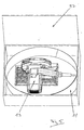
- a further aspect of the invention is based on the invention problem solved by a mobile processing system, an electric processing machine, a guide rail for the Processing machine which is flexible in accordance with the invention or is designed to be movable, and a preferably a cuboid Basic form having transport and storage case with a Storage space includes, whose largest dimension is smaller than the length of the Guide rail in the elongated use configuration is and in which the processing machine together with the in a compact, in particular rolled up or wound up transport and / or storage configuration brought guide rail completely accommodated is.
- the flexible design of the invention allows Guide rail their space-saving accommodation together with the respective processing machine in one compared to the usage length the guide rail small container. Consequently, needs e.g. a craftsman on his way to the construction site with the processing machine and the guide rail containing case only to carry a single object with it, which makes it extremely practical mobile processing system is created.
- the flexible guide rail in their transport or storage configuration as well in already existing transport and storage cases together be housed with the respective processing machines.
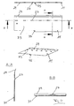
- Fig. 1 shows a thin guide rail 11 according to the invention, the a sheet steel having a thickness of about 0.4 mm is made.
- a base plate 15 of a processing machine 13 here one Circular saw
- the rail 11 is on its top with in a row arranged guide studs 27 provided by embossing the rail material were formed.
- the rail 11 is over its entire length provided with a longitudinally extending bevel 29.
- Fig. 1 shows a conventional processing machine 13
- the base plate 15 has on its underside two parallel offset longitudinal grooves 39.
- the two longitudinal grooves 39 in conjunction with conventional thick guide rails for Querverising the processing machine 13 required.
- the base plate 15 of the circular saw ends in front of the machine Edge region 17 of the guide rail 11.
- Fig. 2 is a in Fig. 1, formed on the base plate 15 crack indicator 25, which reaches up to the edge of the rail and is flush with it.
- the enlarged shown detail X of Fig. 3 shows that the Tool 19 having processing machine is designed such that during pivoting relative to the base plate 15 and thus to the guide rail 11, the pivot axis 23 in the also as the pivot axis plane 21 designated level of the underside of the base plate 15 is located, the with attached to the guide rail 11 machine with the top the guide rail 11 coincides.
- Fig. 3 shows that the rail 11 facing the inside 20 of the saw blade 19 at a distance d from the machine edge of the Rail 11 runs.
- the pivot axis 23 lies in the through this tool inside 20 fixed level.
- tool inclinations of 45 ° is thus between the now oblique extending inside 20 of the tool 19 and the bottom of the Base plate 15 a distance h available.
- the thin invention Guide rail has a thickness which is at most the distance h corresponds, so that - if the maximum pivot angle of the Saw Blade 19 45 ° - the saw blade 19 even at maximum Verschwenkungswinkel not in the way.
- the distance d corresponds to the width of the gap between the tool inside 20 and the crack indicator 25 (see Fig. 1) and is less than 1 mm, preferably between 0.3 and 0.5 mm.
- Fig. 3 is also an alternative position of the tool pivot axis 23 ', which lies in the median plane of the saw blade 19. hereby arise other geometric conditions, the corresponding Adjusting the thickness of the guide rail 11 with simultaneous consideration the maximum pivoting angle of the saw blade 19th require.
- the guide rail 11 is basically also with such processing machines usable, the pivot axes - in the considered at the rail 11 state - not in the plane of Run top of the guide rail. Depending on the position of the swivel axis plane is in the vertical direction then more or less space for the guide rail available.
- guide rail is in that, even if - as it is at the common existing machines is the case - the pivot axis of the Machine is in the area of the rail top and - at high angles of inclination from e.g. 45 ° - that for the guide rail to Available clear height is very low, a transverse displacement of the machine and thus a working under for different Verschwenkungswinkel different conditions can be avoided.
- the various views of the guide rail 11 of Fig. 4 show in particular the design of the guide knobs produced by embossing 27, whose height is smaller in the embodiment shown here is as the raised rail edge at the fold 29.
- the guide rail 11 is not shown in full length and can basically have any length.
- a reduced width end portion of the Rail 11 serves as an attachment region 33 for the respective processing machine.
- the attachment region 33 protrudes beyond the workpiece.
- a downwardly bent tab 35 serves as a stop means for positioning the guide rail 11 on the workpiece in the longitudinal direction as well as an opening aid for a lower guard, as for example in Hand circular saws are often available.
- the Ansetz Schl. 33 can by stiffening means not shown in relation to the rest, in use Stiffened on the workpiece area of the rail 11 stiffened to facilitate the attachment of the machine.
- a friction-increasing Covering 31 which is preferably in the form of a rubber coating is provided and, for example, by a screen printing method the rail base is applied.
- the mobile processing system according to the invention shown in FIG includes a cuboid transport and storage case, in which a processing machine 13, here a circular saw, together with a flexible guide rail 11 according to the invention can be stowed, which is rolled up here to a closed oval.
- a processing machine 13 here a circular saw
- a flexible guide rail 11 according to the invention can be stowed, which is rolled up here to a closed oval.
- the space available in the case 37 can be replaced by the invention Guide rail 11 thus be used optimally.
- the guide rail can be an integral Be part of the machine.
- Fasteners for attachment to the machine can be a such integrated guide rail to be designed exactly as it described above in the introductory part and with reference to the figures has been.
Landscapes
- Engineering & Computer Science (AREA)
- Mechanical Engineering (AREA)
- Sawing (AREA)
- Machine Tool Units (AREA)
- Valve-Gear Or Valve Arrangements (AREA)
- Window Of Vehicle (AREA)
- Electrical Discharge Machining, Electrochemical Machining, And Combined Machining (AREA)
Description
- Fig. 1
- teilweise eine erfindungsgemäße Führungsschiene in Verbindung mit einer Handkreissäge gemäß einer Ausführungsform der Erfindung,
- Fig. 2
- einen rein schematischen Querschnitt durch eine erfindungsgemäße Führungsschiene mit aufgesetzter Bearbeitungsmaschine,
- Fig. 3
- die Einzelheit X von Fig. 2 in vergrößerter Darstellung zur Erläuterung der geometrischen Verhältnisse im Bereich des maschinennahen Randes der erfindungsgemäßen Führungsschiene,
- Fig. 4
- verschiedene Ansichten einer nicht in voller Länge dargestellten Führungsschiene gemäß einer Ausführungsform der Erfindung, und
- Fig. 5
- ein erfindungsgemäßes mobiles Bearbeitungssystem.
- 11
- Führungsschiene
- 13
- Bearbeitungsmaschine, Handkreissäge
- 15
- Grundplatte, Basiseinheit
- 17
- Randbereich
- 19
- Werkzeug
- 20
- Werkzeuginnenseite
- 21
- Schwenkachsenebene
- 23, 23'
- Schwenkachse
- 25
- Rissanzeiger
- 27
- Führungsmittel
- 29
- Abkantung
- 31
- reibungserhöhender Belag
- 33
- Ansetzbereich
- 35
- Anschlagmittel
- 37
- Transport- und Aufbewahrungskoffer
- 39
- Längsnut der Grundplatte
- d
- Arbeitsabstand
- h
- Stärke der Führungsschiene
Claims (22)
- Führungsschiene für elektrische Bearbeitungsmaschinen (13), insbesondere für Handkreissägen, Stichsägen und Oberfräsen, deren Oberseite als Führung für die Bearbeitungsmaschine (13), insbesondere für eine Maschinengrundplatte (15), ausgebildet ist und die mit ihrer Unterseite an ein zu bearbeitendes Werkstück anlegbar ist,
dadurch gekennzeichnet, dass die Schiene (11) zumindest bereichsweise flexibel ausgebildet und aus einer langgestreckten Benutzungskonfiguration in eine kompakte Transport- und/oder Aufbewahrungskonfiguration überführbar ist. - Führungsschiene nach Anspruch 1,
dadurch gekennzeichnet, dass ihre Stärke (h) zumindest in dem dünnen Randbereich (17) höchstens etwa gleich dem Abstand (d) zwischen der Innenseite (20) des Werkzeugs (19) und dem Rand der Schiene (11) bzw. einem maschinenfesten Rissanzeiger (25) ist. - Führungsschiene nach einem der vorhergehenden Ansprüche,
dadurch gekennzeichnet, dass ihre Stärke (h) zumindest in dem dünnen Randbereich (17) weniger als 1 mm beträgt und bevorzugt in einem Bereich von etwa 0,2 bis 0,6 mm, insbesondere von etwa 0,3 bis 0,5 mm liegt. - Führungsschiene nach einem der vorhergehenden Ansprüche,
dadurch gekennzeichnet, dass sie durch Aufrollen oder Aufwickeln in eine geschlossene Ringform mit bevorzugt kreisförmiger, elliptischer oder ovaler Gestalt überführbar ist. - Führungsschiene nach einem der vorhergehenden Ansprüche,
dadurch gekennzeichnet, dass sie einstückig ausgebildet ist. - Führungsschiene nach einem der vorhergehenden Ansprüche,
dadurch gekennzeichnet, dass sie aus Blechmaterial hergestellt ist, insbesondere aus Stahlblech. - Führungsschiene nach einem der vorhergehenden Ansprüche,
dadurch gekennzeichnet, dass als Führungsmittel für die Bearbeitungsmaschine (13) eine Vielzahl von diskreten, in Längsrichtung mit Abstand voneinander angeordneten, insbesondere noppenartigen Führungsvorsprüngen (27) auf der Oberseite der Schiene (11) vorgesehen ist. - Führungsschiene nach einem der vorhergehenden Ansprüche,
dadurch gekennzeichnet, dass als Führungsmittel für die Bearbeitungsmaschine (13) durch Materialverformung, insbesondere durch Prägen, gebildete Führungserhebungen (27) auf der Oberseite der Schiene (11) vorgesehen sind. - Führungsschiene nach einem der vorhergehenden Ansprüche,
dadurch gekennzeichnet, dass sie mit Versteifungsmitteln (29) versehen ist, die ihr einerseits in der langgestreckten Benutzungskonfiguration eine erhöhte Formstabilität verleihen, andererseits ein Überführen in eine kompakte Transport- und/oder Aufbewahrungskonfiguration insbesondere durch Aufrollen oder Aufwickeln zulassen. - Führungsschiene nach Anspruch 9,
dadurch gekennzeichnet, dass die Versteifungsmittel in Form von wenigstens einer Längsabkantung (29) vorgesehen sind. - Führungsschiene nach einem der vorhergehenden Ansprüche,
dadurch gekennzeichnet, dass sie an zumindest einem Ende einen im Betrieb über das Werkstück hinausragenden Ansetzbereich (33) erhöhter Steifigkeit aufweist, wobei bevorzugt der Ansetzbereich (33) zur Positionierung der Schiene (11) am Werkstück dienende Anschlagmittel (35) aufweist, die insbesondere gleichzeitig zum Öffnen einer unteren Schutzhaube z.B. einer Handkreissäge ausgebildet sind. - Führungsschiene nach einem der vorhergehenden Ansprüche,
dadurch gekennzeichnet, dass die Unterseite der Schiene (11) mit einem reibungserhöhenden Belag (31) insbesondere in Form einer Gummierung oder Beflockung versehen ist, wobei bevorzugt der Belag (31) durch ein Siebdruckverfahren aufgebracht ist. - Führungsschiene nach einem der vorhergehenden Ansprüche,
dadurch gekennzeichnet, dass sie eine Länge von mehr als 1 m und insbesondere von mehreren Metern aufweist. - Elektrische Bearbeitungsmaschine, insbesondere Handkreissäge, Stichsäge oder Oberfräse, mit einer integrierten Führungsschiene (11), die an einer längs der Führungsschiene (11) bewegbaren und ein im Betrieb bis unter die Führungsschiene (11) vorstehendes Werkzeug (19) aufweisenden Maschineneinheit befestigt ist und die Merkmale eines der Ansprüche 1 bis 13 aufweist.
- Bearbeitungsmaschine nach Anspruch 14,
dadurch gekennzeichnet, dass die Maschineneinheit eine Basiseinheit (15), an der die Führungsschiene (11) befestigt ist, und eine das Werkzeug (19) umfassende Werkzeugeinheit umfasst, wobei die Werkzeugeinheit relativ zur Basiseinheit (15) und damit zur Führungsschiene (11) verschwenkbar ist. - Bearbeitungsmaschine nach Anspruch 15,
dadurch gekennzeichnet, dass die Schwenkachse (23) der Werkzeugeinheit etwa in der Ebene (21) der Oberseite der Führungsschiene (11) liegt. - Bearbeitungsmaschine nach Anspruch 15 oder 16,
dadurch gekennzeichnet, dass die Schwenkachse (23) der Werkzeugeinheit etwa in der Ebene der der Führungsschiene (11) zugewandten Innenseite (20) des Werkzeugs (19) liegt. - Bearbeitungsmaschine nach einem der Ansprüche 15 bis 17,
dadurch gekennzeichnet, dass Werkzeugneigungen von 0° bis wenigstens 45° bezogen auf eine parallel zur Oberseite der Führungsschiene (11) verlaufende Ebene einstellbar sind. - Bearbeitungsmaschine nach einem der Ansprüche 15 bis 18,
dadurch gekennzeichnet, dass der Abstand der der Führungsschiene (11) zugewandten Innenseite (20) des Werkzeugs (19) von dem Rand der Führungsschiene (11) bzw. einem maschinenfesten, insbesondere an der Basiseinheit ausgebildeten Rissanzeiger (25) etwa gleich der Stärke der Schiene (11) in ihrem dem Werkzeug (19) zugewandten Randbereich (17) ist. - Mobiles Bearbeitungssystem miteiner elektrischen Bearbeitungsmaschine (13), insbesondere einer Handkreissäge, Stichsäge oder Oberfräse,einer Führungsschiene (11) für die Bearbeitungsmaschine (13) mit den Merkmalen eines der Ansprüche 1 bis 13, undeinem bevorzugt eine quaderförmige Grundform aufweisenden Transport- und Aufbewahrungskoffer (37) mit einem Stauraum, dessen größte Abmessung kleiner als die Länge der Führungsschiene (11) in der langgestreckten Benutzungskonfiguration ist und in dem die Bearbeitungsmaschine (13) zusammen mit der in eine kompakte, insbesondere aufgerollte oder aufgewickelte Transport- und/oder Aufbewahrungskonfiguration gebrachten Führungsschiene (11) vollständig unterbringbar ist.
- Bearbeitungssystem nach Anspruch 20,
dadurch gekennzeichnet, dass die Führungsschiene (11) aufgerollt oder aufgewickelt auf der Seite liegend, dabei eine Gestalt mit kreisförmiger, elliptischer oder ovaler Transport- und/oder Aufbewahrungskonfiguration einnehmend und die Bearbeitungsmaschine (13) in dem von der aufgerollten oder aufgewickelten Führungsschiene (11) umschlossenen Bereich liegend oder stehend im Transport- und Aufbewahrungskoffer (37) unterbringbar sind. - System mitwobei die Führungsschiene (11) derart dünn ausgeführt ist, dass sie auch bei in der Ebene (21) ihrer Oberseite verlaufender Werkzeugschwenkachse (23, 23') und mit einem von Null verschiedenen Arbeitsabstand (d) vom Rand der Schiene (11) bzw. von einem maschinenfesten Rissanzeiger (25) positioniertem Werkzeug (19) vollständig außerhalb des vorzugsweise Werkzeugneigungen von 0° bis wenigstens 45° umfassenden Schwenkbereiches des Werkzeugs (19) liegt.einer elektrischen Bearbeitungsmaschine (13), insbesondere einer Handkreissäge, Stichsäge oder Oberfräse, undeiner Führungsschiene (11) für die Bearbeitungsmaschine (13) mit den Merkmalen eines der Ansprüche 1 bis 13,
Applications Claiming Priority (2)
| Application Number | Priority Date | Filing Date | Title |
|---|---|---|---|
| DE10220363 | 2002-05-07 | ||
| DE10220363A DE10220363A1 (de) | 2002-05-07 | 2002-05-07 | Führungsschiene |
Publications (3)
| Publication Number | Publication Date |
|---|---|
| EP1361019A2 EP1361019A2 (de) | 2003-11-12 |
| EP1361019A3 EP1361019A3 (de) | 2003-11-19 |
| EP1361019B1 true EP1361019B1 (de) | 2005-10-12 |
Family
ID=29225083
Family Applications (1)
| Application Number | Title | Priority Date | Filing Date |
|---|---|---|---|
| EP03004547A Expired - Lifetime EP1361019B1 (de) | 2002-05-07 | 2003-02-28 | Führungsschiene |
Country Status (3)
| Country | Link |
|---|---|
| EP (1) | EP1361019B1 (de) |
| AT (1) | ATE306357T1 (de) |
| DE (2) | DE10220363A1 (de) |
Cited By (4)
| Publication number | Priority date | Publication date | Assignee | Title |
|---|---|---|---|---|
| DE102018113477A1 (de) | 2018-06-06 | 2019-12-12 | Wolfcraft Gmbh | Führungsschiene mit Führungsschlitten für eine Handkreissäge |
| US12083613B2 (en) | 2022-10-18 | 2024-09-10 | Techtronic Cordless Gp | Track saw including plunge lockout mechanism |
| US12263615B2 (en) | 2020-11-23 | 2025-04-01 | Milwaukee Electric Tool Corporation | Circular saw |
| US12465982B2 (en) | 2022-02-24 | 2025-11-11 | Techtronic Cordless Gp | Track saw including plunge lockout mechanism |
Families Citing this family (5)
| Publication number | Priority date | Publication date | Assignee | Title |
|---|---|---|---|---|
| DE102009029108A1 (de) * | 2009-09-02 | 2011-03-03 | Robert Bosch Gmbh | Handwerkzeugmaschinenanordnung mit einer Handwerkzeugmaschine und mit einer Führungsschiene |
| DE102010032989A1 (de) * | 2010-07-31 | 2012-02-02 | Festool Gmbh | Führungsvorrichtung für eine Hand-Werkzeugmaschine |
| EP2412489B1 (de) * | 2010-07-31 | 2016-06-22 | Festool GmbH | Führungsvorrichtung für eine Hand-Werkzeugmaschine |
| DE102011000515B4 (de) * | 2011-02-04 | 2023-07-06 | Wolfcraft Gmbh | Stationär und mobil betreibbare Sägevorrichtung |
| DE102020100574B4 (de) | 2020-01-13 | 2024-02-08 | Festool Gmbh | Führungsschiene zum Führen einer Hand-Werkzeugmaschine |
Family Cites Families (3)
| Publication number | Priority date | Publication date | Assignee | Title |
|---|---|---|---|---|
| US4463644A (en) * | 1981-02-19 | 1984-08-07 | Hirsh Company | Straight edge guide |
| AU2647684A (en) * | 1983-04-06 | 1984-10-11 | Clough, Gwenyth Joy | Circular saw guide |
| DE3606525C2 (de) * | 1986-02-28 | 1996-05-02 | Black & Decker Inc | Führungseinrichtung für Elektrohandwerkzeuge |
-
2002
- 2002-05-07 DE DE10220363A patent/DE10220363A1/de not_active Withdrawn
-
2003
- 2003-02-28 DE DE50301337T patent/DE50301337D1/de not_active Expired - Lifetime
- 2003-02-28 EP EP03004547A patent/EP1361019B1/de not_active Expired - Lifetime
- 2003-02-28 AT AT03004547T patent/ATE306357T1/de not_active IP Right Cessation
Cited By (4)
| Publication number | Priority date | Publication date | Assignee | Title |
|---|---|---|---|---|
| DE102018113477A1 (de) | 2018-06-06 | 2019-12-12 | Wolfcraft Gmbh | Führungsschiene mit Führungsschlitten für eine Handkreissäge |
| US12263615B2 (en) | 2020-11-23 | 2025-04-01 | Milwaukee Electric Tool Corporation | Circular saw |
| US12465982B2 (en) | 2022-02-24 | 2025-11-11 | Techtronic Cordless Gp | Track saw including plunge lockout mechanism |
| US12083613B2 (en) | 2022-10-18 | 2024-09-10 | Techtronic Cordless Gp | Track saw including plunge lockout mechanism |
Also Published As
| Publication number | Publication date |
|---|---|
| EP1361019A3 (de) | 2003-11-19 |
| DE50301337D1 (de) | 2006-02-23 |
| DE10220363A1 (de) | 2003-12-04 |
| ATE306357T1 (de) | 2005-10-15 |
| EP1361019A2 (de) | 2003-11-12 |
Similar Documents
| Publication | Publication Date | Title |
|---|---|---|
| EP1361019B1 (de) | Führungsschiene | |
| DE20019548U1 (de) | Variable Kreisbogenschablone | |
| DE2726382C3 (de) | Vorrichtung zum Bohren und Ausschneiden oder Fräsen eines Bauteiles aus einem plattenförmigen Werkstück aus Holz o.dgl | |
| EP3802002B1 (de) | Vorrichtung mit führungsschlitten für eine handkreissäge | |
| DE3333169C2 (de) | ||
| EP1027952B1 (de) | Holzbearbeitungsanlage in Portalbauweise | |
| EP0930120A2 (de) | Trennsäge mit einem verstellbaren Auflagetisch | |
| EP0362833A2 (de) | Holzbearbeitungsmaschine, insbesondere Kehlmaschine | |
| DE2332454B2 (de) | Fuehrungsvorrichtung fuer handbandschleifmaschinen oder dergleichen | |
| AT408628B (de) | Parallelanschlagsvorrichtung für eine formatsägemaschine | |
| DE2743313A1 (de) | Maschine fuer die spanende bearbeitung von flaechen | |
| DE3249732C2 (en) | Guide plate for the controlled guiding of a portable saw | |
| DE102008018674B3 (de) | Vertikalschneidemaschine für Schaumstoff oder andere Materialien | |
| DE2804536C2 (de) | Einrichtung zum Zertrennen von Blöcken aus geschäumtem Kunststoff oder ähnlichem Material, insbesondere zum Formschneiden | |
| DE3434469A1 (de) | Saegeschablone fuer eine elektrische handsaege | |
| WO1997017176A2 (de) | Schutzvorrichtung für kreissägen | |
| DE2759768C2 (de) | Schutzhaubenhalter aus Blech für eine Tischkreissäge | |
| DE1503976C3 (de) | Doppelrollwagen zur Aufnahme des Werkstückes bei Format- und Besäumkreissägen | |
| DE2158191C3 (de) | Vorrichtung zum Entgraten von geraden Blechbändern | |
| EP2186588B1 (de) | Kapp- und Gehrungssäge | |
| DE9413397U1 (de) | Trennvorrichtung | |
| EP0683005A1 (de) | Werkstückhaltevorrichtung für Unterflur-Zugkreissägen | |
| DE3623102A1 (de) | Schneidvorrichtung fuer bodenbelaege | |
| DE29810050U1 (de) | Tischkreissäge | |
| DE602005005691T2 (de) | Abricht- und/oder Hobelmaschine mit Schutzhaube für ein Schneidwerkzeug |
Legal Events
| Date | Code | Title | Description |
|---|---|---|---|
| PUAI | Public reference made under article 153(3) epc to a published international application that has entered the european phase |
Free format text: ORIGINAL CODE: 0009012 |
|
| PUAL | Search report despatched |
Free format text: ORIGINAL CODE: 0009013 |
|
| AK | Designated contracting states |
Kind code of ref document: A2 Designated state(s): AT BE BG CH CY CZ DE DK EE ES FI FR GB GR HU IE IT LI LU MC NL PT SE SI SK TR |
|
| AX | Request for extension of the european patent |
Extension state: AL LT LV MK RO |
|
| AK | Designated contracting states |
Kind code of ref document: A3 Designated state(s): AT BE BG CH CY CZ DE DK EE ES FI FR GB GR HU IE IT LI LU MC NL PT SE SI SK TR |
|
| AX | Request for extension of the european patent |
Extension state: AL LT LV MK RO |
|
| AKX | Designation fees paid | ||
| 17P | Request for examination filed |
Effective date: 20031208 |
|
| RBV | Designated contracting states (corrected) |
Designated state(s): AT BE BG CH CY CZ DE DK EE ES FI FR GB GR HU IE IT LI LU MC NL PT SE SI SK TR |
|
| REG | Reference to a national code |
Ref country code: DE Ref legal event code: 8566 |
|
| 17Q | First examination report despatched |
Effective date: 20041029 |
|
| GRAP | Despatch of communication of intention to grant a patent |
Free format text: ORIGINAL CODE: EPIDOSNIGR1 |
|
| GRAS | Grant fee paid |
Free format text: ORIGINAL CODE: EPIDOSNIGR3 |
|
| GRAA | (expected) grant |
Free format text: ORIGINAL CODE: 0009210 |
|
| AK | Designated contracting states |
Kind code of ref document: B1 Designated state(s): AT BE BG CH CY CZ DE DK EE ES FI FR GB GR HU IE IT LI LU MC NL PT SE SI SK TR |
|
| PG25 | Lapsed in a contracting state [announced via postgrant information from national office to epo] |
Ref country code: NL Free format text: LAPSE BECAUSE OF FAILURE TO SUBMIT A TRANSLATION OF THE DESCRIPTION OR TO PAY THE FEE WITHIN THE PRESCRIBED TIME-LIMIT Effective date: 20051012 Ref country code: CZ Free format text: LAPSE BECAUSE OF FAILURE TO SUBMIT A TRANSLATION OF THE DESCRIPTION OR TO PAY THE FEE WITHIN THE PRESCRIBED TIME-LIMIT Effective date: 20051012 Ref country code: SK Free format text: LAPSE BECAUSE OF FAILURE TO SUBMIT A TRANSLATION OF THE DESCRIPTION OR TO PAY THE FEE WITHIN THE PRESCRIBED TIME-LIMIT Effective date: 20051012 Ref country code: IE Free format text: LAPSE BECAUSE OF FAILURE TO SUBMIT A TRANSLATION OF THE DESCRIPTION OR TO PAY THE FEE WITHIN THE PRESCRIBED TIME-LIMIT Effective date: 20051012 Ref country code: SI Free format text: LAPSE BECAUSE OF FAILURE TO SUBMIT A TRANSLATION OF THE DESCRIPTION OR TO PAY THE FEE WITHIN THE PRESCRIBED TIME-LIMIT Effective date: 20051012 Ref country code: FI Free format text: LAPSE BECAUSE OF FAILURE TO SUBMIT A TRANSLATION OF THE DESCRIPTION OR TO PAY THE FEE WITHIN THE PRESCRIBED TIME-LIMIT Effective date: 20051012 |
|
| REG | Reference to a national code |
Ref country code: GB Ref legal event code: FG4D Free format text: NOT ENGLISH |
|
| REG | Reference to a national code |
Ref country code: CH Ref legal event code: EP |
|
| REG | Reference to a national code |
Ref country code: IE Ref legal event code: FG4D Free format text: LANGUAGE OF EP DOCUMENT: GERMAN |
|
| GBT | Gb: translation of ep patent filed (gb section 77(6)(a)/1977) |
Effective date: 20051130 |
|
| PG25 | Lapsed in a contracting state [announced via postgrant information from national office to epo] |
Ref country code: DK Free format text: LAPSE BECAUSE OF FAILURE TO SUBMIT A TRANSLATION OF THE DESCRIPTION OR TO PAY THE FEE WITHIN THE PRESCRIBED TIME-LIMIT Effective date: 20060112 Ref country code: BG Free format text: LAPSE BECAUSE OF FAILURE TO SUBMIT A TRANSLATION OF THE DESCRIPTION OR TO PAY THE FEE WITHIN THE PRESCRIBED TIME-LIMIT Effective date: 20060112 Ref country code: SE Free format text: LAPSE BECAUSE OF FAILURE TO SUBMIT A TRANSLATION OF THE DESCRIPTION OR TO PAY THE FEE WITHIN THE PRESCRIBED TIME-LIMIT Effective date: 20060112 Ref country code: GR Free format text: LAPSE BECAUSE OF FAILURE TO SUBMIT A TRANSLATION OF THE DESCRIPTION OR TO PAY THE FEE WITHIN THE PRESCRIBED TIME-LIMIT Effective date: 20060112 |
|
| PG25 | Lapsed in a contracting state [announced via postgrant information from national office to epo] |
Ref country code: ES Free format text: LAPSE BECAUSE OF FAILURE TO SUBMIT A TRANSLATION OF THE DESCRIPTION OR TO PAY THE FEE WITHIN THE PRESCRIBED TIME-LIMIT Effective date: 20060123 |
|
| REF | Corresponds to: |
Ref document number: 50301337 Country of ref document: DE Date of ref document: 20060223 Kind code of ref document: P |
|
| PG25 | Lapsed in a contracting state [announced via postgrant information from national office to epo] |
Ref country code: MC Free format text: LAPSE BECAUSE OF NON-PAYMENT OF DUE FEES Effective date: 20060228 Ref country code: AT Free format text: LAPSE BECAUSE OF NON-PAYMENT OF DUE FEES Effective date: 20060228 Ref country code: BE Free format text: LAPSE BECAUSE OF NON-PAYMENT OF DUE FEES Effective date: 20060228 Ref country code: LU Free format text: LAPSE BECAUSE OF NON-PAYMENT OF DUE FEES Effective date: 20060228 |
|
| PG25 | Lapsed in a contracting state [announced via postgrant information from national office to epo] |
Ref country code: PT Free format text: LAPSE BECAUSE OF FAILURE TO SUBMIT A TRANSLATION OF THE DESCRIPTION OR TO PAY THE FEE WITHIN THE PRESCRIBED TIME-LIMIT Effective date: 20060313 |
|
| NLV1 | Nl: lapsed or annulled due to failure to fulfill the requirements of art. 29p and 29m of the patents act | ||
| PG25 | Lapsed in a contracting state [announced via postgrant information from national office to epo] |
Ref country code: HU Free format text: LAPSE BECAUSE OF FAILURE TO SUBMIT A TRANSLATION OF THE DESCRIPTION OR TO PAY THE FEE WITHIN THE PRESCRIBED TIME-LIMIT Effective date: 20060413 |
|
| REG | Reference to a national code |
Ref country code: IE Ref legal event code: FD4D |
|
| ET | Fr: translation filed | ||
| PLBE | No opposition filed within time limit |
Free format text: ORIGINAL CODE: 0009261 |
|
| STAA | Information on the status of an ep patent application or granted ep patent |
Free format text: STATUS: NO OPPOSITION FILED WITHIN TIME LIMIT |
|
| 26N | No opposition filed |
Effective date: 20060713 |
|
| BERE | Be: lapsed |
Owner name: MAFELL A.G. Effective date: 20060228 |
|
| PG25 | Lapsed in a contracting state [announced via postgrant information from national office to epo] |
Ref country code: EE Free format text: LAPSE BECAUSE OF FAILURE TO SUBMIT A TRANSLATION OF THE DESCRIPTION OR TO PAY THE FEE WITHIN THE PRESCRIBED TIME-LIMIT Effective date: 20051012 |
|
| PG25 | Lapsed in a contracting state [announced via postgrant information from national office to epo] |
Ref country code: TR Free format text: LAPSE BECAUSE OF FAILURE TO SUBMIT A TRANSLATION OF THE DESCRIPTION OR TO PAY THE FEE WITHIN THE PRESCRIBED TIME-LIMIT Effective date: 20051012 |
|
| PG25 | Lapsed in a contracting state [announced via postgrant information from national office to epo] |
Ref country code: CY Free format text: LAPSE BECAUSE OF FAILURE TO SUBMIT A TRANSLATION OF THE DESCRIPTION OR TO PAY THE FEE WITHIN THE PRESCRIBED TIME-LIMIT Effective date: 20051012 |
|
| PGFP | Annual fee paid to national office [announced via postgrant information from national office to epo] |
Ref country code: GB Payment date: 20130218 Year of fee payment: 11 |
|
| GBPC | Gb: european patent ceased through non-payment of renewal fee |
Effective date: 20140228 |
|
| PG25 | Lapsed in a contracting state [announced via postgrant information from national office to epo] |
Ref country code: GB Free format text: LAPSE BECAUSE OF NON-PAYMENT OF DUE FEES Effective date: 20140228 |
|
| REG | Reference to a national code |
Ref country code: FR Ref legal event code: PLFP Year of fee payment: 14 |
|
| REG | Reference to a national code |
Ref country code: FR Ref legal event code: PLFP Year of fee payment: 15 |
|
| PGFP | Annual fee paid to national office [announced via postgrant information from national office to epo] |
Ref country code: IT Payment date: 20170221 Year of fee payment: 15 |
|
| REG | Reference to a national code |
Ref country code: FR Ref legal event code: PLFP Year of fee payment: 16 |
|
| PG25 | Lapsed in a contracting state [announced via postgrant information from national office to epo] |
Ref country code: IT Free format text: LAPSE BECAUSE OF NON-PAYMENT OF DUE FEES Effective date: 20180228 |
|
| PGFP | Annual fee paid to national office [announced via postgrant information from national office to epo] |
Ref country code: DE Payment date: 20190429 Year of fee payment: 17 |
|
| PGFP | Annual fee paid to national office [announced via postgrant information from national office to epo] |
Ref country code: CH Payment date: 20200219 Year of fee payment: 18 |
|
| PGFP | Annual fee paid to national office [announced via postgrant information from national office to epo] |
Ref country code: FR Payment date: 20200219 Year of fee payment: 18 |
|
| REG | Reference to a national code |
Ref country code: DE Ref legal event code: R119 Ref document number: 50301337 Country of ref document: DE |
|
| PG25 | Lapsed in a contracting state [announced via postgrant information from national office to epo] |
Ref country code: DE Free format text: LAPSE BECAUSE OF NON-PAYMENT OF DUE FEES Effective date: 20200901 |
|
| PG25 | Lapsed in a contracting state [announced via postgrant information from national office to epo] |
Ref country code: CH Free format text: LAPSE BECAUSE OF NON-PAYMENT OF DUE FEES Effective date: 20210228 Ref country code: LI Free format text: LAPSE BECAUSE OF NON-PAYMENT OF DUE FEES Effective date: 20210228 |
|
| PG25 | Lapsed in a contracting state [announced via postgrant information from national office to epo] |
Ref country code: FR Free format text: LAPSE BECAUSE OF NON-PAYMENT OF DUE FEES Effective date: 20210228 |