EP1358054B1 - Method and apparatus for manufacturing containers with out-of-centre mouth - Google Patents
Method and apparatus for manufacturing containers with out-of-centre mouth Download PDFInfo
- Publication number
- EP1358054B1 EP1358054B1 EP02718051A EP02718051A EP1358054B1 EP 1358054 B1 EP1358054 B1 EP 1358054B1 EP 02718051 A EP02718051 A EP 02718051A EP 02718051 A EP02718051 A EP 02718051A EP 1358054 B1 EP1358054 B1 EP 1358054B1
- Authority
- EP
- European Patent Office
- Prior art keywords
- preform
- rod
- blow
- preforms
- counter
- Prior art date
- Legal status (The legal status is an assumption and is not a legal conclusion. Google has not performed a legal analysis and makes no representation as to the accuracy of the status listed.)
- Expired - Lifetime
Links
- 238000000034 method Methods 0.000 title claims abstract description 15
- 238000004519 manufacturing process Methods 0.000 title claims abstract description 4
- 238000000071 blow moulding Methods 0.000 claims abstract description 26
- 239000004033 plastic Substances 0.000 claims abstract description 3
- 238000007664 blowing Methods 0.000 claims description 17
- 229920005992 thermoplastic resin Polymers 0.000 claims description 3
- 238000000926 separation method Methods 0.000 claims description 2
- 238000000465 moulding Methods 0.000 claims 1
- 238000010438 heat treatment Methods 0.000 abstract 3
- 230000003750 conditioning effect Effects 0.000 abstract 1
- 238000003825 pressing Methods 0.000 abstract 1
- 230000033001 locomotion Effects 0.000 description 8
- 230000001788 irregular Effects 0.000 description 2
- 230000015572 biosynthetic process Effects 0.000 description 1
- 238000007796 conventional method Methods 0.000 description 1
- 238000002425 crystallisation Methods 0.000 description 1
- 230000008025 crystallization Effects 0.000 description 1
- 230000006837 decompression Effects 0.000 description 1
- 239000003599 detergent Substances 0.000 description 1
- 230000000694 effects Effects 0.000 description 1
- 230000007717 exclusion Effects 0.000 description 1
- 238000001125 extrusion Methods 0.000 description 1
- 239000000314 lubricant Substances 0.000 description 1
- 238000012423 maintenance Methods 0.000 description 1
- 239000000463 material Substances 0.000 description 1
- 230000000149 penetrating effect Effects 0.000 description 1
- 230000035515 penetration Effects 0.000 description 1
- 230000000717 retained effect Effects 0.000 description 1
- 230000001360 synchronised effect Effects 0.000 description 1
Images


Classifications
-
- B—PERFORMING OPERATIONS; TRANSPORTING
- B29—WORKING OF PLASTICS; WORKING OF SUBSTANCES IN A PLASTIC STATE IN GENERAL
- B29C—SHAPING OR JOINING OF PLASTICS; SHAPING OF MATERIAL IN A PLASTIC STATE, NOT OTHERWISE PROVIDED FOR; AFTER-TREATMENT OF THE SHAPED PRODUCTS, e.g. REPAIRING
- B29C49/00—Blow-moulding, i.e. blowing a preform or parison to a desired shape within a mould; Apparatus therefor
- B29C49/42—Component parts, details or accessories; Auxiliary operations
- B29C49/70—Removing or ejecting blown articles from the mould
-
- B—PERFORMING OPERATIONS; TRANSPORTING
- B29—WORKING OF PLASTICS; WORKING OF SUBSTANCES IN A PLASTIC STATE IN GENERAL
- B29C—SHAPING OR JOINING OF PLASTICS; SHAPING OF MATERIAL IN A PLASTIC STATE, NOT OTHERWISE PROVIDED FOR; AFTER-TREATMENT OF THE SHAPED PRODUCTS, e.g. REPAIRING
- B29C49/00—Blow-moulding, i.e. blowing a preform or parison to a desired shape within a mould; Apparatus therefor
- B29C49/08—Biaxial stretching during blow-moulding
- B29C49/10—Biaxial stretching during blow-moulding using mechanical means for prestretching
- B29C49/12—Stretching rods
-
- B—PERFORMING OPERATIONS; TRANSPORTING
- B29—WORKING OF PLASTICS; WORKING OF SUBSTANCES IN A PLASTIC STATE IN GENERAL
- B29C—SHAPING OR JOINING OF PLASTICS; SHAPING OF MATERIAL IN A PLASTIC STATE, NOT OTHERWISE PROVIDED FOR; AFTER-TREATMENT OF THE SHAPED PRODUCTS, e.g. REPAIRING
- B29C49/00—Blow-moulding, i.e. blowing a preform or parison to a desired shape within a mould; Apparatus therefor
- B29C49/42—Component parts, details or accessories; Auxiliary operations
- B29C49/64—Heating or cooling preforms, parisons or blown articles
- B29C49/6409—Thermal conditioning of preforms
- B29C49/6436—Thermal conditioning of preforms characterised by temperature differential
-
- B—PERFORMING OPERATIONS; TRANSPORTING
- B29—WORKING OF PLASTICS; WORKING OF SUBSTANCES IN A PLASTIC STATE IN GENERAL
- B29C—SHAPING OR JOINING OF PLASTICS; SHAPING OF MATERIAL IN A PLASTIC STATE, NOT OTHERWISE PROVIDED FOR; AFTER-TREATMENT OF THE SHAPED PRODUCTS, e.g. REPAIRING
- B29C49/00—Blow-moulding, i.e. blowing a preform or parison to a desired shape within a mould; Apparatus therefor
- B29C49/42—Component parts, details or accessories; Auxiliary operations
- B29C49/70—Removing or ejecting blown articles from the mould
- B29C2049/701—Ejecting means
- B29C2049/702—Air pressure
Definitions
- the present invention refers to a particular method for manufacturing containers of thermoplastic resin, in particular PET, that are provided with a cylindrical neck portion, on which a normal cap is then screwed, but have a body that is formed to a shape which is asymmetrical with respect to all planes passing through the axis of said neck portion of the container, with the exclusion of a single plane thereof, which therefore forms the one and single plane of symmetry of the container.
- Containers of this kind are usually manufactured by initially obtaining a preform through the extrusion in an appropriate manner of a molten mass of pelletized plastic material, and then submitting such a preform to blow-moulding so as to cause it to take the desired shape of the finished container.
- These containers shall be called “asymmetrical” in this context for the sole reason that this is how they are usually referred to in the common practice; they are universally used in particular applications and fields of utilization that require a considerable reduction in a total available volume with respect to the sum of the volumes of a determined number of containers included in said total volume. It is a largely well-known fact that the containers featuring a good "volumetric efficiency" are those containers whose shape comes as close as possible to a parallelepiped.
- such containers shall possess a good prehensility, ie. shall be particularly adapted to convenient grasping or seizing, since they are most likely to be handled by hands that may not be very well fit, ie. in a suitable condition for seizing them.
- typical fields of utilization of these containers are when they contain, ie. are filled with lubricant oil or detergent.
- Containers of this kind are manufactured starting from fully traditional and therefore, cylindrical preforms, although it would be possible, albeit very complicated, demanding and expensive, for these containers to be manufactured starting from preforms that are actually so shaped as to as much as possible anticipate the ultimate shape of the blow-moulded container.
- the step in which the preforms are blow-moulded in view of obtaining said asymmetrical containers has the following substantial drawback connected with the downward stretching of the preform.
- the actual blow-moulding step comprises following two sub-steps: a first sub-step in which an appropriate stretching rod is inserted deeply down into the preform so as to push the bottom of the preform against the matching portion, ie. the bottom of the blowing mould and, as a result, to so determine the correct height dimension of the finished container; and a second, subsequent sub-step, in which compressed air is let into the preform.
- the bottom of the preform is blown partially.
- the end portion of the stretching rod fails to touch the bottom of the preform, but comes instead into contact with a more or less lateral zone; therefore, such a circumstance causes the blow-moulding effect to become still more irregular and uncertain, while the resulting container quite frequently exhibits distortions, deformations or even cracks that make it completely useless.
- the French patent no. 2508004 granted to AOKI, discloses a solution that makes use of a contrasting and reference rod 12 that acts as an abutment on the outside of the bottom of the container during blow-moulding; in this solution, however, the purpose of said rod is completely different from the one involving the positioning of the bottom of the container, since it can be clearly inferred that such a bottom is fully stretched and, therefore, guided by the stretching rod prior to the beginning of the step in which the compressed air is let in, so that no teaching is actually given in view of maintaining the correct position of the bottom during the initial part of the blowing process, but prior to the beginning of the penetration movement of the stretching rod, since in this case blowing only starts after said stretching rod has fully moved into the preform.
- An air ejector hole for product removal is provided at the centre of the ejector pin.
- said pin is not able to engage against a portion of the outer surface of the bottom of the opposite preform during the movement of the stretching rod into said preform, that would endanger the blowing results, mainly when asymmetrical bottles are blown.
- JP 6238742 a method to control the wall thickness distribution of a hollow moulded product is known; said method is based on the fact that the wall thickness distribution is depending also on the temperature distribution of the inner wall of a temperature control pot containing the hollow moulded product.
- Said method is useful for providing special and not-symmetrical items, as for example a handled bottle.
- the present invention may take the form of a preferred, although not sole embodiment such as the one that is described in detail and illustrated below by way of non-limiting example with reference to the accompanying drawings, in which:
- the present invention covers the provision of asymmetrical blow-moulding cavities that are provided with a particular apparatus adapted to carry out the process described below,
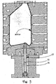
- the blowing mould further to the asymmetrical cavity 10 and the stretching rod 11, is also provided with a counter-rod 12, which is arranged in alignment with said stretching rod 11 on the opposite side thereof with respect to the blow-moulding cavity.
- This counter-rod 12 is delimited at its end portions by a terminal zone 13, which is oriented towards the interior of the blow-moulding cavity and, therefore, towards the stretching rod, and by the opposite terminal zone 14.
- the counter-rod 12 is further provided slidably within an appropriate housing in such a manner as to ensure that the sliding axis "S" of the stretching rod is the same as the one of this counter-rod.
- this counter-rod are controllable and actuatable pneumatically; to this purpose, in fact, the outer terminal zone 14 thereof is provided with a piston 15 that is adapted to be guided within a channel 16 provided in a body 17 that is firmly joined to or integral with said blow-moulding cavity.
- a piston 15 is actuatable pneumatically by means of a forced flow of gas that is let into and blown off said channel 16 in a controlled manner.
- Said counter-rod 12 is therefore adapted to be pushed into said blow-moulding cavity 10 until the terminal zone 13 thereof is brought to almost come into contact with, ie. touch the bottom 18 of the preform and, by interrupting the pressure exerted by the gas let into the channel 16, it can be ejected out of said blow-moulding cavity owing to the pushing action exerted by the bottom of the preform being in turn pushed in the same direction by the stretching rod.
- the preform is blow-moulded under admittance of gas under pressure into said preform, while the stretching rod is at the same time caused to fully move into the preform itself.
- the bottom of the preform 19 enters into contact with the terminal zone 13 of the counter-rod, which is therefore pushed outwards with a movement that is fully synchronous with the movement of the stretching rod on the other side.
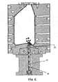
- an advantageous improvement of the present invention consists in providing said counter-rod 12 with an inner longitudinal cavity 21 communicating with the outside of said terminal zone 13, ie. the one which enters into contact with the preform, through a plurality of through-perforations 22 (Figure 5).
- Such a cavity 21 is connected to a gas source, the delivery of which is capable of being controlled both in the timing and the pressure of the gas supply.
- the operation of the thus resulting counter-rod 12 therefore consists; further to its already described sliding motion into the blow-moulding cavity, in issuing gas jets from said through-perforations 22 upon completion of the blow-moulding sub-step and prior to the opening of the blowing mould, in such a manner as to enable these gas jets to promote the separation of said terminal zone 13 of the counter-rod from the bottom of the blow-moulded hollow body, so as to free the latter from any constraint that might affect or slow down a correct removal thereof from the mould ( Figure 6).
Landscapes
- Engineering & Computer Science (AREA)
- Manufacturing & Machinery (AREA)
- Mechanical Engineering (AREA)
- Physics & Mathematics (AREA)
- Thermal Sciences (AREA)
- Blow-Moulding Or Thermoforming Of Plastics Or The Like (AREA)
- Processing And Handling Of Plastics And Other Materials For Molding In General (AREA)
- Moulds For Moulding Plastics Or The Like (AREA)
- Supplying Of Containers To The Packaging Station (AREA)
- Container Filling Or Packaging Operations (AREA)
Applications Claiming Priority (3)
| Application Number | Priority Date | Filing Date | Title |
|---|---|---|---|
| IT2001PN000009A ITPN20010009A1 (it) | 2001-02-07 | 2001-02-07 | Procedimento per la produzione di contenitori in pet con bocca fuoricentro |
| ITPN20010009 | 2001-02-07 | ||
| PCT/EP2002/000834 WO2002062549A2 (en) | 2001-02-07 | 2002-01-26 | Method and apparatus for conditioning pet preforms and method and apparatus for manufacturing pet containers with out-of-center mouth |
Publications (2)
| Publication Number | Publication Date |
|---|---|
| EP1358054A2 EP1358054A2 (en) | 2003-11-05 |
| EP1358054B1 true EP1358054B1 (en) | 2005-07-27 |
Family
ID=11453218
Family Applications (1)
| Application Number | Title | Priority Date | Filing Date |
|---|---|---|---|
| EP02718051A Expired - Lifetime EP1358054B1 (en) | 2001-02-07 | 2002-01-26 | Method and apparatus for manufacturing containers with out-of-centre mouth |
Country Status (13)
| Country | Link |
|---|---|
| US (1) | US20040070119A1 (enExample) |
| EP (1) | EP1358054B1 (enExample) |
| JP (1) | JP4146234B2 (enExample) |
| CN (1) | CN1257049C (enExample) |
| AT (1) | ATE300407T1 (enExample) |
| BR (1) | BR0206789B1 (enExample) |
| DE (1) | DE60205215T2 (enExample) |
| ES (1) | ES2247313T3 (enExample) |
| IT (1) | ITPN20010009A1 (enExample) |
| MX (1) | MXPA03007066A (enExample) |
| PL (1) | PL201334B1 (enExample) |
| RU (1) | RU2261176C2 (enExample) |
| WO (1) | WO2002062549A2 (enExample) |
Cited By (1)
| Publication number | Priority date | Publication date | Assignee | Title |
|---|---|---|---|---|
| EP3348374A1 (en) * | 2014-03-03 | 2018-07-18 | Amcor Group GmbH | Machine component facilitating mold base movement |
Families Citing this family (19)
| Publication number | Priority date | Publication date | Assignee | Title |
|---|---|---|---|---|
| GB0306547D0 (en) * | 2003-03-21 | 2003-04-23 | Engineering Business Ltd | Apparatus for creating a local reduction in wave height |
| US20050073077A1 (en) * | 2003-09-09 | 2005-04-07 | Whitley Kenneth W. | Use of air assist to eject roller bottle with deep punt |
| US20060204694A1 (en) | 2005-03-08 | 2006-09-14 | Silgan Plastics Corporation | Bottle with extended neck finish and method of making same |
| ES2315910T3 (es) * | 2005-07-28 | 2009-04-01 | Sidel Participations | Molde para una maquina de moldeo por soplado de recipientes, que comprende una parte inferior del molde ranurada. |
| US8573964B2 (en) * | 2006-04-13 | 2013-11-05 | Amcor Limited | Liquid or hydraulic blow molding |
| US8017064B2 (en) | 2007-12-06 | 2011-09-13 | Amcor Limited | Liquid or hydraulic blow molding |
| DE102008013419A1 (de) * | 2008-03-06 | 2009-09-10 | Khs Corpoplast Gmbh & Co. Kg | Verfahren und Vorrichtung zur Blasformung von Behältern |
| DE102008049905A1 (de) * | 2008-10-02 | 2010-04-08 | Krones Ag | Schnellwechselsystem für Reckstangen |
| FR2966374B1 (fr) * | 2010-10-26 | 2014-06-27 | Sidel Participations | Perfectionnement au support de fond de moule pour le faconnage d'un recipient en matiere thermoplastique |
| WO2013063461A1 (en) * | 2011-10-27 | 2013-05-02 | Amcor Limited | Counter stretch connecting rod and positive fill level control rod |
| WO2013063453A1 (en) | 2011-10-27 | 2013-05-02 | Amcor Limited | Method and apparatus for forming and filling a container |
| BR112014015428B1 (pt) | 2011-12-21 | 2020-11-17 | Amcor Limited | sistema de vedação para máquina de moldagem |
| EP2794235B1 (en) | 2011-12-22 | 2018-07-18 | Discma AG | Method for controlling temperature gradient through wall thickness of container |
| EP3233420B2 (en) * | 2014-12-19 | 2024-05-29 | The Coca-Cola Company | Gas-assisted base blow off methods for blow molding applications |
| FR3043354B1 (fr) * | 2015-11-06 | 2017-12-22 | Sidel Participations | Moule equipe d'une tige de contre-etirage interchangeable |
| CN106226026B (zh) * | 2016-07-28 | 2019-11-08 | 中国航天空气动力技术研究院 | 测量模型的六自由度位移和姿态的方法 |
| FR3080055A1 (fr) * | 2018-04-16 | 2019-10-18 | Sidel Participations | Unite de moulage avec orifice de passage de col decentre |
| CN113453869B (zh) * | 2019-02-21 | 2024-01-12 | 日精Asb机械株式会社 | 偏心容器的制造方法及温度调整用模具 |
| EP4299279A4 (en) * | 2021-02-25 | 2025-04-02 | Nissei ASB Machine Co., Ltd. | TEMPERATURE CONTROL MOLD, AND RESIN CONTAINER PRODUCTION DEVICE AND METHOD |
Family Cites Families (28)
| Publication number | Priority date | Publication date | Assignee | Title |
|---|---|---|---|---|
| US3316594A (en) * | 1961-10-09 | 1967-05-02 | Monsanto Co | Method and apparatus for making containers of thermoformable material |
| DE1904753A1 (de) * | 1969-01-31 | 1970-08-13 | Rainer Fischer | Verfahren und Vorrichtung zum Herstellen von Hohlkoerpern aus thermoplastischem Kunststoff |
| US4050876A (en) * | 1973-11-14 | 1977-09-27 | Monsanto Company | Rotary stretch blow molding apparatus |
| JPS58123029U (ja) * | 1982-02-15 | 1983-08-22 | 株式会社吉野工業所 | 2軸延伸ブロ−成形機における底部金型装置 |
| DE3363881D1 (en) * | 1982-04-12 | 1986-07-10 | Siegfried Shankar Roy | Injection blow molding apparatus |
| JPH0761675B2 (ja) * | 1990-06-18 | 1995-07-05 | 凸版印刷株式会社 | プラスチックボトルの製造方法 |
| JP2911557B2 (ja) * | 1990-07-11 | 1999-06-23 | 大日本印刷株式会社 | 樹脂製予備成形体、それを用いた二軸延伸ブロー成形容器及びその製造方法 |
| JPH0681700B2 (ja) * | 1990-09-25 | 1994-10-19 | 東洋製罐株式会社 | 二軸延伸プラスチックボトルの製造方法 |
| FR2678542B1 (fr) * | 1991-07-01 | 1993-10-29 | Sidel | Procede et installation pour le chauffage, par rayonnement infrarouge, de preformes en matiere plastique, notamment en pet, destinees a la fabrication de recipients. |
| JPH0524099A (ja) * | 1991-07-18 | 1993-02-02 | Denki Kagaku Kogyo Kk | 二軸延伸ブロー成形方法及びそのブロー金型 |
| JP3218670B2 (ja) * | 1992-03-30 | 2001-10-15 | 凸版印刷株式会社 | パリソンの温度調節方法 |
| JPH05345350A (ja) * | 1992-06-15 | 1993-12-27 | Denki Kagaku Kogyo Kk | 二軸延伸ブロー容器の成形方法とその金型 |
| US5292243A (en) * | 1992-09-28 | 1994-03-08 | Cincinnati Milacron Inc. | Apparatus for heating portions of container preforms |
| JPH06238742A (ja) * | 1993-02-17 | 1994-08-30 | Mitsubishi Plastics Ind Ltd | 射出延伸吹込成形方法 |
| JP3255485B2 (ja) * | 1993-03-25 | 2002-02-12 | 日精エー・エス・ビー機械株式会社 | ブロー成形機 |
| JP3340183B2 (ja) * | 1993-04-01 | 2002-11-05 | 日精エー・エス・ビー機械株式会社 | 成形装置 |
| FR2703944B1 (fr) * | 1993-04-15 | 1995-06-23 | Sidel Sa | Procédé et installation pour le traitement thermique du corps d'une préforme en matériau thermoplastique. |
| DE4402295C1 (de) * | 1994-01-24 | 1995-10-12 | Intus Inst Fuer Technologie Un | Vorrichtung zur Profilierung von gerundeten Behältnissen und rohrförmigen Werkstücken |
| US5501593A (en) * | 1994-04-07 | 1996-03-26 | Marcus; Paul | Parison molding apparatus |
| TW378178B (en) * | 1994-09-16 | 2000-01-01 | Nissei Asb Machine Co Ltd | Injection-stretch-blow moulding apparatus |
| JP3612775B2 (ja) * | 1995-03-28 | 2005-01-19 | 東洋製罐株式会社 | 耐熱耐圧自立容器及びその製造方法 |
| RU2143340C1 (ru) * | 1996-01-12 | 1999-12-27 | Курт Х. Руппман | Способ изготовления формованного пластмассового контейнера |
| JPH1071641A (ja) * | 1996-08-31 | 1998-03-17 | Yoshino Kogyosho Co Ltd | 2軸延伸ブロー成形の成形金型装置 |
| US5853775A (en) * | 1997-12-05 | 1998-12-29 | Electra Form, Inc. | Non-Round container blow molding apparatus |
| JPH11207806A (ja) * | 1998-01-27 | 1999-08-03 | Kao Corp | 射出延伸ブロー成形体の製造方法 |
| JP2000102970A (ja) * | 1998-09-28 | 2000-04-11 | Mitsubishi Plastics Ind Ltd | ボトル成形用金型 |
| US6367765B1 (en) * | 1999-09-09 | 2002-04-09 | Klaus A. Wieder | Mold vent |
| JP4336425B2 (ja) * | 1999-09-22 | 2009-09-30 | 北海製罐株式会社 | ブロー成形方法 |
-
2001
- 2001-02-07 IT IT2001PN000009A patent/ITPN20010009A1/it unknown
-
2002
- 2002-01-26 CN CN02804643.9A patent/CN1257049C/zh not_active Expired - Fee Related
- 2002-01-26 US US10/467,452 patent/US20040070119A1/en not_active Abandoned
- 2002-01-26 ES ES02718051T patent/ES2247313T3/es not_active Expired - Lifetime
- 2002-01-26 RU RU2003127844/12A patent/RU2261176C2/ru not_active IP Right Cessation
- 2002-01-26 BR BRPI0206789-7A patent/BR0206789B1/pt not_active IP Right Cessation
- 2002-01-26 WO PCT/EP2002/000834 patent/WO2002062549A2/en not_active Ceased
- 2002-01-26 DE DE60205215T patent/DE60205215T2/de not_active Expired - Lifetime
- 2002-01-26 EP EP02718051A patent/EP1358054B1/en not_active Expired - Lifetime
- 2002-01-26 JP JP2002562538A patent/JP4146234B2/ja not_active Expired - Lifetime
- 2002-01-26 AT AT02718051T patent/ATE300407T1/de not_active IP Right Cessation
- 2002-01-26 MX MXPA03007066A patent/MXPA03007066A/es active IP Right Grant
- 2002-01-26 PL PL363514A patent/PL201334B1/pl unknown
Cited By (4)
| Publication number | Priority date | Publication date | Assignee | Title |
|---|---|---|---|---|
| EP3348374A1 (en) * | 2014-03-03 | 2018-07-18 | Amcor Group GmbH | Machine component facilitating mold base movement |
| US10232545B2 (en) | 2014-03-03 | 2019-03-19 | Amcor Rigid Plastics Usa, Llc | Machine component facilitating mold base movement |
| EP3348374B1 (en) | 2014-03-03 | 2020-08-26 | Amcor Rigid Plastics USA, LLC | Machine component facilitating mold base movement |
| EP3348375B1 (en) | 2014-03-03 | 2020-09-09 | Amcor Rigid Plastics USA, LLC | Machine component facilitating mold base movement |
Also Published As
| Publication number | Publication date |
|---|---|
| WO2002062549A2 (en) | 2002-08-15 |
| CN1525906A (zh) | 2004-09-01 |
| RU2003127844A (ru) | 2005-02-27 |
| ITPN20010009A1 (it) | 2002-08-07 |
| CN1257049C (zh) | 2006-05-24 |
| RU2261176C2 (ru) | 2005-09-27 |
| ATE300407T1 (de) | 2005-08-15 |
| PL201334B1 (pl) | 2009-03-31 |
| BR0206789B1 (pt) | 2011-06-28 |
| MXPA03007066A (es) | 2004-05-24 |
| US20040070119A1 (en) | 2004-04-15 |
| BR0206789A (pt) | 2004-02-17 |
| EP1358054A2 (en) | 2003-11-05 |
| PL363514A1 (en) | 2004-11-29 |
| ES2247313T3 (es) | 2006-03-01 |
| WO2002062549A3 (en) | 2002-11-21 |
| JP4146234B2 (ja) | 2008-09-10 |
| JP2004529789A (ja) | 2004-09-30 |
| DE60205215T2 (de) | 2006-06-01 |
| DE60205215D1 (de) | 2005-09-01 |
Similar Documents
| Publication | Publication Date | Title |
|---|---|---|
| EP1358054B1 (en) | Method and apparatus for manufacturing containers with out-of-centre mouth | |
| US3767747A (en) | Method for blow molding | |
| KR0165919B1 (ko) | 사출연신취입성형에 있어서의 프리포옴 성형방법 | |
| CA1194659A (en) | Apparatus for biaxial-blow-molding hollow bottle- shaped container of synthetic resin and method of biaxial-blow-molding the same container | |
| US4540543A (en) | Injection blow molding process and apparatus | |
| KR100189402B1 (ko) | 대형 용기의 연신취입성형방법 | |
| US4323341A (en) | Apparatus for forming hollow plastic objects | |
| US3806300A (en) | Apparatus for forming the neck on a plastic container | |
| JP7457077B2 (ja) | 首曲がり容器の製造方法、温度調整用金型、ブロー成形装置およびブロー成形方法 | |
| DK152568B (da) | Fremgangsmaade og apparat til biaksial blaeseformning af hule plastgenstande | |
| JP4714509B2 (ja) | 射出延伸ブロー成形方法 | |
| US3940225A (en) | Blow molding apparatus for staged inflation of an extruded parison | |
| CA1076764A (en) | Extendible porous core rod or pin and process and apparatus for using same | |
| US11325288B2 (en) | Method and device for the production of an optimized neck contour on preforms | |
| BR9403739A (pt) | Processo para a moldagem por injeção com estiramento por insuflação de polietileno | |
| US4242300A (en) | Method for processing parisons | |
| US4207134A (en) | Apparatus for the preparation of hollow plastic articles | |
| US4230298A (en) | Apparatus for the preparation of hollow plastic articles | |
| USRE29065E (en) | Method for blow molding | |
| CN216832152U (zh) | 用于对预成型坯进行充气的拉伸杆以及装置 | |
| JP2004059129A (ja) | 底部に吊り具を有するボトル及びその成形方法と射出金型 |
Legal Events
| Date | Code | Title | Description |
|---|---|---|---|
| PUAI | Public reference made under article 153(3) epc to a published international application that has entered the european phase |
Free format text: ORIGINAL CODE: 0009012 |
|
| 17P | Request for examination filed |
Effective date: 20030703 |
|
| AK | Designated contracting states |
Kind code of ref document: A2 Designated state(s): AT BE CH CY DE DK ES FI FR GB GR IE IT LI LU MC NL PT SE TR |
|
| 17Q | First examination report despatched |
Effective date: 20031125 |
|
| GRAP | Despatch of communication of intention to grant a patent |
Free format text: ORIGINAL CODE: EPIDOSNIGR1 |
|
| RTI1 | Title (correction) |
Free format text: METHOD AND APPARATUS FOR MANUFACTURING CONTAINERS WITH OUT-OF-CENTRE MOUTH |
|
| GRAS | Grant fee paid |
Free format text: ORIGINAL CODE: EPIDOSNIGR3 |
|
| GRAA | (expected) grant |
Free format text: ORIGINAL CODE: 0009210 |
|
| AK | Designated contracting states |
Kind code of ref document: B1 Designated state(s): AT BE CH CY DE DK ES FI FR GB GR IE IT LI LU MC NL PT SE TR |
|
| PG25 | Lapsed in a contracting state [announced via postgrant information from national office to epo] |
Ref country code: LI Free format text: LAPSE BECAUSE OF FAILURE TO SUBMIT A TRANSLATION OF THE DESCRIPTION OR TO PAY THE FEE WITHIN THE PRESCRIBED TIME-LIMIT Effective date: 20050727 Ref country code: AT Free format text: LAPSE BECAUSE OF FAILURE TO SUBMIT A TRANSLATION OF THE DESCRIPTION OR TO PAY THE FEE WITHIN THE PRESCRIBED TIME-LIMIT Effective date: 20050727 Ref country code: CH Free format text: LAPSE BECAUSE OF FAILURE TO SUBMIT A TRANSLATION OF THE DESCRIPTION OR TO PAY THE FEE WITHIN THE PRESCRIBED TIME-LIMIT Effective date: 20050727 Ref country code: BE Free format text: LAPSE BECAUSE OF FAILURE TO SUBMIT A TRANSLATION OF THE DESCRIPTION OR TO PAY THE FEE WITHIN THE PRESCRIBED TIME-LIMIT Effective date: 20050727 Ref country code: NL Free format text: LAPSE BECAUSE OF FAILURE TO SUBMIT A TRANSLATION OF THE DESCRIPTION OR TO PAY THE FEE WITHIN THE PRESCRIBED TIME-LIMIT Effective date: 20050727 Ref country code: FI Free format text: LAPSE BECAUSE OF FAILURE TO SUBMIT A TRANSLATION OF THE DESCRIPTION OR TO PAY THE FEE WITHIN THE PRESCRIBED TIME-LIMIT Effective date: 20050727 |
|
| REG | Reference to a national code |
Ref country code: GB Ref legal event code: FG4D |
|
| REG | Reference to a national code |
Ref country code: CH Ref legal event code: EP |
|
| REG | Reference to a national code |
Ref country code: IE Ref legal event code: FG4D |
|
| REF | Corresponds to: |
Ref document number: 60205215 Country of ref document: DE Date of ref document: 20050901 Kind code of ref document: P |
|
| PG25 | Lapsed in a contracting state [announced via postgrant information from national office to epo] |
Ref country code: DK Free format text: LAPSE BECAUSE OF FAILURE TO SUBMIT A TRANSLATION OF THE DESCRIPTION OR TO PAY THE FEE WITHIN THE PRESCRIBED TIME-LIMIT Effective date: 20051027 Ref country code: SE Free format text: LAPSE BECAUSE OF FAILURE TO SUBMIT A TRANSLATION OF THE DESCRIPTION OR TO PAY THE FEE WITHIN THE PRESCRIBED TIME-LIMIT Effective date: 20051027 Ref country code: GR Free format text: LAPSE BECAUSE OF FAILURE TO SUBMIT A TRANSLATION OF THE DESCRIPTION OR TO PAY THE FEE WITHIN THE PRESCRIBED TIME-LIMIT Effective date: 20051027 |
|
| PG25 | Lapsed in a contracting state [announced via postgrant information from national office to epo] |
Ref country code: PT Free format text: LAPSE BECAUSE OF FAILURE TO SUBMIT A TRANSLATION OF THE DESCRIPTION OR TO PAY THE FEE WITHIN THE PRESCRIBED TIME-LIMIT Effective date: 20051227 |
|
| PG25 | Lapsed in a contracting state [announced via postgrant information from national office to epo] |
Ref country code: IE Free format text: LAPSE BECAUSE OF NON-PAYMENT OF DUE FEES Effective date: 20060126 |
|
| PG25 | Lapsed in a contracting state [announced via postgrant information from national office to epo] |
Ref country code: LU Free format text: LAPSE BECAUSE OF NON-PAYMENT OF DUE FEES Effective date: 20060131 Ref country code: MC Free format text: LAPSE BECAUSE OF NON-PAYMENT OF DUE FEES Effective date: 20060131 |
|
| REG | Reference to a national code |
Ref country code: CH Ref legal event code: PL |
|
| NLV1 | Nl: lapsed or annulled due to failure to fulfill the requirements of art. 29p and 29m of the patents act | ||
| REG | Reference to a national code |
Ref country code: ES Ref legal event code: FG2A Ref document number: 2247313 Country of ref document: ES Kind code of ref document: T3 |
|
| ET | Fr: translation filed | ||
| PLBE | No opposition filed within time limit |
Free format text: ORIGINAL CODE: 0009261 |
|
| STAA | Information on the status of an ep patent application or granted ep patent |
Free format text: STATUS: NO OPPOSITION FILED WITHIN TIME LIMIT |
|
| 26N | No opposition filed |
Effective date: 20060428 |
|
| REG | Reference to a national code |
Ref country code: IE Ref legal event code: MM4A |
|
| PG25 | Lapsed in a contracting state [announced via postgrant information from national office to epo] |
Ref country code: CY Free format text: LAPSE BECAUSE OF FAILURE TO SUBMIT A TRANSLATION OF THE DESCRIPTION OR TO PAY THE FEE WITHIN THE PRESCRIBED TIME-LIMIT Effective date: 20050727 |
|
| PG25 | Lapsed in a contracting state [announced via postgrant information from national office to epo] |
Ref country code: IT Free format text: LAPSE BECAUSE OF NON-PAYMENT OF DUE FEES Effective date: 20090126 |
|
| PGRI | Patent reinstated in contracting state [announced from national office to epo] |
Ref country code: IT Effective date: 20110616 |
|
| REG | Reference to a national code |
Ref country code: FR Ref legal event code: PLFP Year of fee payment: 15 |
|
| PGFP | Annual fee paid to national office [announced via postgrant information from national office to epo] |
Ref country code: GB Payment date: 20160217 Year of fee payment: 15 |
|
| REG | Reference to a national code |
Ref country code: FR Ref legal event code: PLFP Year of fee payment: 16 |
|
| GBPC | Gb: european patent ceased through non-payment of renewal fee |
Effective date: 20170126 |
|
| PG25 | Lapsed in a contracting state [announced via postgrant information from national office to epo] |
Ref country code: GB Free format text: LAPSE BECAUSE OF NON-PAYMENT OF DUE FEES Effective date: 20170126 |
|
| REG | Reference to a national code |
Ref country code: FR Ref legal event code: PLFP Year of fee payment: 17 |
|
| PGFP | Annual fee paid to national office [announced via postgrant information from national office to epo] |
Ref country code: DE Payment date: 20190122 Year of fee payment: 18 |
|
| PGFP | Annual fee paid to national office [announced via postgrant information from national office to epo] |
Ref country code: TR Payment date: 20200122 Year of fee payment: 19 |
|
| REG | Reference to a national code |
Ref country code: DE Ref legal event code: R119 Ref document number: 60205215 Country of ref document: DE |
|
| PG25 | Lapsed in a contracting state [announced via postgrant information from national office to epo] |
Ref country code: DE Free format text: LAPSE BECAUSE OF NON-PAYMENT OF DUE FEES Effective date: 20200801 |
|
| PGFP | Annual fee paid to national office [announced via postgrant information from national office to epo] |
Ref country code: FR Payment date: 20210129 Year of fee payment: 20 |
|
| REG | Reference to a national code |
Ref country code: ES Ref legal event code: FD2A Effective date: 20210604 |
|
| PG25 | Lapsed in a contracting state [announced via postgrant information from national office to epo] |
Ref country code: ES Free format text: LAPSE BECAUSE OF NON-PAYMENT OF DUE FEES Effective date: 20200127 |
|
| PGFP | Annual fee paid to national office [announced via postgrant information from national office to epo] |
Ref country code: IT Payment date: 20210129 Year of fee payment: 20 |