EP1354750A1 - Ensemble d'équipement de véhicule automobile comportant des moyens de connexion électrique améliorés - Google Patents
Ensemble d'équipement de véhicule automobile comportant des moyens de connexion électrique améliorés Download PDFInfo
- Publication number
- EP1354750A1 EP1354750A1 EP03290888A EP03290888A EP1354750A1 EP 1354750 A1 EP1354750 A1 EP 1354750A1 EP 03290888 A EP03290888 A EP 03290888A EP 03290888 A EP03290888 A EP 03290888A EP 1354750 A1 EP1354750 A1 EP 1354750A1
- Authority
- EP
- European Patent Office
- Prior art keywords
- equipment
- piece
- assembly according
- connection part
- positioning
- Prior art date
- Legal status (The legal status is an assumption and is not a legal conclusion. Google has not performed a legal analysis and makes no representation as to the accuracy of the status listed.)
- Granted
Links
- 230000000295 complement effect Effects 0.000 claims description 20
- 230000008878 coupling Effects 0.000 claims description 5
- 238000010168 coupling process Methods 0.000 claims description 5
- 238000005859 coupling reaction Methods 0.000 claims description 5
- 230000007935 neutral effect Effects 0.000 claims description 4
- 238000000429 assembly Methods 0.000 description 3
- 210000000056 organ Anatomy 0.000 description 2
- 238000013459 approach Methods 0.000 description 1
- 238000002788 crimping Methods 0.000 description 1
- 238000009434 installation Methods 0.000 description 1
- 238000000034 method Methods 0.000 description 1
Images


Classifications
-
- H—ELECTRICITY
- H05—ELECTRIC TECHNIQUES NOT OTHERWISE PROVIDED FOR
- H05K—PRINTED CIRCUITS; CASINGS OR CONSTRUCTIONAL DETAILS OF ELECTRIC APPARATUS; MANUFACTURE OF ASSEMBLAGES OF ELECTRICAL COMPONENTS
- H05K7/00—Constructional details common to different types of electric apparatus
- H05K7/14—Mounting supporting structure in casing or on frame or rack
- H05K7/1438—Back panels or connecting means therefor; Terminals; Coding means to avoid wrong insertion
- H05K7/1452—Mounting of connectors; Switching; Reinforcing of back panels
- H05K7/1454—Alignment mechanisms; Drawout cases
-
- B—PERFORMING OPERATIONS; TRANSPORTING
- B60—VEHICLES IN GENERAL
- B60K—ARRANGEMENT OR MOUNTING OF PROPULSION UNITS OR OF TRANSMISSIONS IN VEHICLES; ARRANGEMENT OR MOUNTING OF PLURAL DIVERSE PRIME-MOVERS IN VEHICLES; AUXILIARY DRIVES FOR VEHICLES; INSTRUMENTATION OR DASHBOARDS FOR VEHICLES; ARRANGEMENTS IN CONNECTION WITH COOLING, AIR INTAKE, GAS EXHAUST OR FUEL SUPPLY OF PROPULSION UNITS IN VEHICLES
- B60K35/00—Instruments specially adapted for vehicles; Arrangement of instruments in or on vehicles
- B60K35/60—Instruments characterised by their location or relative disposition in or on vehicles
-
- H—ELECTRICITY
- H01—ELECTRIC ELEMENTS
- H01R—ELECTRICALLY-CONDUCTIVE CONNECTIONS; STRUCTURAL ASSOCIATIONS OF A PLURALITY OF MUTUALLY-INSULATED ELECTRICAL CONNECTING ELEMENTS; COUPLING DEVICES; CURRENT COLLECTORS
- H01R13/00—Details of coupling devices of the kinds covered by groups H01R12/70 or H01R24/00 - H01R33/00
- H01R13/62—Means for facilitating engagement or disengagement of coupling parts or for holding them in engagement
- H01R13/629—Additional means for facilitating engagement or disengagement of coupling parts, e.g. aligning or guiding means, levers, gas pressure electrical locking indicators, manufacturing tolerances
- H01R13/631—Additional means for facilitating engagement or disengagement of coupling parts, e.g. aligning or guiding means, levers, gas pressure electrical locking indicators, manufacturing tolerances for engagement only
- H01R13/6315—Additional means for facilitating engagement or disengagement of coupling parts, e.g. aligning or guiding means, levers, gas pressure electrical locking indicators, manufacturing tolerances for engagement only allowing relative movement between coupling parts, e.g. floating connection
-
- H—ELECTRICITY
- H01—ELECTRIC ELEMENTS
- H01R—ELECTRICALLY-CONDUCTIVE CONNECTIONS; STRUCTURAL ASSOCIATIONS OF A PLURALITY OF MUTUALLY-INSULATED ELECTRICAL CONNECTING ELEMENTS; COUPLING DEVICES; CURRENT COLLECTORS
- H01R2201/00—Connectors or connections adapted for particular applications
- H01R2201/26—Connectors or connections adapted for particular applications for vehicles
Definitions
- the invention relates to the field of equipment for motor vehicles.
- a main object of the invention is to render assembly operations of the type described above minus tedious and simpler for an operator, even to render the automated operation, and to automatically catch up, during assembly, the relative positioning clearances of the connecting pieces.
- the second part of electrical connection is mounted on the piece of equipment corresponding with play in at least one direction substantially orthogonal to the direction of assembly, and includes a third guide and positioning member complementary to the first, so that the first organ of guidance and positioning defines a unique reference of relative positioning of pieces of equipment and relative positioning of the first and second parts of connection.
- connection parts are housings complementary to each other, in each of which are accommodated by respective contacts, complementary to those housed in the consideration of connection box.
- connection parts is a housing in which pressure type contacts are housed, while the other of the connection parts includes conductive surfaces formed on the circuit board printed, said surfaces receiving said supports pressure type contacts.
- the third form of guidance and positioning is directly formed in the printed circuit board.
- the invention applies more particularly to the fixing of a electrical equipment on a dashboard, a panel door, center console, seat or even a roof.
- This electrical equipment can be constituted, as this has already been mentioned, from a dashboard, but also from a car radio, a control console, or a display.
- axis X-X corresponds to the longitudinal axis of the vehicle (horizontal) facing forward
- Y-Y axis corresponds to the transverse (horizontal) axis oriented from right to left
- Z-Z axis is the vertical axis oriented from bottom up.
- FIG 1 part of a dashboard 1, in which a cavity 3 is formed.
- the dashboard 1 constitutes a first part of equipment fixed inside the vehicle and intended for receive in its cavity 3 a second piece of equipment consisting of a dashboard, which will be described in reference to Figure 2.
- a block 5 for receiving and fixing a male electrical connector 7.
- the connector electric male 7 is shown alone, it being understood that is actually, in the configuration shown, wired.
- the wiring harness connected to male electrical connector 7 is not shown, and has traveled in a classic way since the engine compartment up to the connector 7 placed, in the passenger compartment, crossing the cavity 3.
- the beam of cables could either come from the dashboard 1 herself.
- the receiving and fixing block 5 includes means for fixing the male electrical connector 7, of the type conventional, for example latching means, screwing, crimping or other; these fixing means were therefore not represented.
- a rail 9 molded with the dashboard 1 extends, in the example shown, along the axis longitudinal X-X, which will define the axis of assembly of the connection parts on the pieces of equipment, and the axis for coupling the connecting parts together. he goes of course that this reference axis was chosen arbitrarily, and that, depending on the nature of the equipment and its location in the vehicle, any other axis would be suitable for the illustration of the invention.
- Rail 9 has a U-shaped cross section overturned and cooperates with a notch 11 of shape complementary opening onto a lower face of the male electrical connector 7.
- the rail 9 constitutes a member guide and positioning of the electrical connector male 7 relative to the dashboard 1 and in particular relative to the cavity 3.
- the male electrical connector 7 is guided, when it is fixed on the dashboard 1, longitudinally to block 5, and positions it so accurate with respect to this one.
- the dashboard 14 includes for example electrical displays, dials, which are not visible in the Figure since the dashboard 14 is oriented so as to show its part intended for cooperate with the cavity 3 of the dashboard 1.
- the dashboard 14 has a collar 16 delimiting a receptacle 18.
- This receptacle 18 receives a bottom plate 20 whose outer edges 22 are provided to coincide, at least partially, with the inner surface 24 of the collar 16.
- the bottom plate 20 consisting of a circuit printed with the side facing the inside of the vehicle supports indicator lights, dials or other displays, it constitutes a visible part for a user placed in the passenger compartment of the vehicle. These indicator lights, dials, displays, etc. are visible from the inside of the vehicle through windows 25 with respect to which they must be positioned relatively precisely. he it is therefore important that the bottom plate 20 is positioned relatively precisely in receptacle 18.
- Conventional fasteners 26 of the switchboard edge 14 on the edge plank 1 are arranged on the outer periphery of the dashboard 14.
- the bottom plate 20 is integral with a connector electric female 28 complementary to the connector electric male 7 fixed on the dashboard 1.
- a straight rail 30 is formed extending along the longitudinal axis of vehicle X-X.
- the rail 30, constituting a second guide and positioning, has a U-shaped cross section overturned, the bottom of which is hollow complementary to the rail 9.
- a notch 32 formed on a underside of the female electrical connector 28, constitutes a third guiding and positioning (or rail), also complementary to the rail 9.
- Locking in axial position of the assembly formed by the female connector 28 and the bottom plate 20 is produced by elastically deformable legs 34, arranged on the inner edges 24 of the collar 16 and cooperating with the outer edges 22 of the bottom plate 20, as well as by axial stops 35.
- the rail 32 of the connector female 28 extends substantially in the extension of the rail 30 of the dashboard, by abutment of the two rails 30, 32.
- Plate 20 is susceptible to slight transverse movements relative to the dashboard 14 from the neutral position thus defined.
- the plate 20 therefore has a clearance in at least one direction, preferably two directions Y-Y, Z-Z, substantially orthogonal to the mounting direction X-X in receptacle 18.
- the transverse play along the Y-Y axis may be greater than 1.5 mm, of the order of 2 mm.
- the transverse play along the vertical axis Z-Z can be of the order of 0.5 mm.
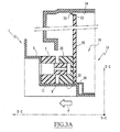
- elastic members 33 ( Figures 3A and 3B), the action of which is oriented mainly in the direction of play between the outer edges 22 of the plate 20 and the inner edges 24 of the collar 16.
- These elastic return members 33 may consist of tabs protruding from the flange 16 towards the edges 22. In the example shown, such a tab 33 acting in the direction of the vertical clearance of the plate 20, presses it down by pressing its edge lower on rail 9.
- the two sub-assemblies are shown in FIG. 3A facing each other, in a pre-assembled position, so that we understand that the rail 30, by its lower surface, and the notch 32 are adapted for cooperate with rail 9.
- the assembled sub-assembly formed by the dashboard 14, the female connector 28 and the bottom plate 20 can slide on the rail 9 to the dashboard 14 fully inserted position in the cavity 3 on the one hand, and the male electrical connector 7 in the female electrical connector 28 on the other hand.
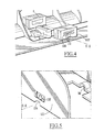
- connection part 107 intended to be fixed on block 5 consists of a box in which is housed a contact carrier module 109.
- Contacts 111 are inserted and maintained in the contact carrier module 109, said contacts 111 being of the “pressure” type, that is to say that they are designed to cooperate with a surface conductive by pressing on it.
- the contacts 111 are mounted in the contact carrier module 109 so as to slightly protrude from said contact carrier module 109 in direction of the connection counterparty, the two parties of connection being, when coupled, maintained between them with a suitable clamping force.
- FIG. 2 there is also shown a dashboard of the type shown in Figure 2, in its region including guide rail 30.
- the second part of connection associated with the first part 107 is essentially consisting of conductive tracks 122 intended to receive pressure contacts 111 in support, formed on a printed circuit board 120 analogous to the plate 20 of the first embodiment.
- connection parts 107, 122 have not been represented, but we understand that they can be of any suitable type, and act directly or indirectly on connection parts 107, 122.
- a form of guide 124 complementary to the rail 9 is practiced directly in the printed circuit board 120 under the configuration of a complementary notch of the rail 9.
- This second embodiment illustrates that the invention cannot be limited to the most common type of connectors, in which the two complementary parts of connection consist of a male connector and a female connector. On the contrary, the invention is conceived for many types of connectors and equipment vehicle.
- the guide and positioning 30 allows not only to position with relative accuracy of the electrical connection part 28; 122 on the associated piece of equipment 14, but also ensure precise positioning of the connection parts 7, 28; 107, 122 relative to each other, and simultaneously pieces of equipment 1, 14 one by compared to each other.
- the assembly with play of one of the parts of connection on his piece of equipment ensures the both a reliable electrical connection and respect for clearances and outcrops between the different rooms.
- This positioning is carried out in relation to a unique reference constituted by rail 9, since all the parts of the assembly are centered on it. It results in the simultaneous solution by means common and with a low number of parts, the problems of positioning of the pieces of equipment in relation to the other, which have a significant impact on the aesthetics of the interior of the vehicle, and alignment problems connector parts prior to their coupling.
Landscapes
- Engineering & Computer Science (AREA)
- Microelectronics & Electronic Packaging (AREA)
- Chemical & Material Sciences (AREA)
- Combustion & Propulsion (AREA)
- Transportation (AREA)
- Mechanical Engineering (AREA)
- Fittings On The Vehicle Exterior For Carrying Loads, And Devices For Holding Or Mounting Articles (AREA)
- Instrument Panels (AREA)
- Motor Or Generator Frames (AREA)
- Details Of Connecting Devices For Male And Female Coupling (AREA)
- Automobile Manufacture Line, Endless Track Vehicle, Trailer (AREA)
Abstract
Description
- une première partie de connexion électrique montée sur une première pièce d'équipement, la première pièce d'équipement comprenant un premier organe de guidage et de positionnement permettant le guidage suivant une direction d'assemblage et le positionnement relatifs de la première partie de connexion électrique sur la première pièce d'êquipement,
- une deuxième pièce d'équipement comprenant un deuxième organe de guidage et de positionnement complémentaire du premier permettant le guidage et le positionnement relatifs de la deuxième pièce d'équipement sur la première pièce d'équipement,
- une deuxième partie de connexion électrique complémentaire de la première, montée sur la deuxième pièce d'équipement.
- la deuxième partie de connexion est montée sur la deuxième pièce d'équipement avec un jeu dans deux directions sensiblement orthogonales à la direction d'assemblage;
- le jeu dans au moins une direction sensiblement orthogonale à la direction d'assemblage est supérieur à 1,5 mm, de préférence de l'ordre de 2 mm ;
- l'ensemble d'équipement comporte des moyens élastiques de sollicitation de la deuxième partie de connexion vers une position neutre par rapport à la deuxième pièce d'équipement, agissant dans au moins une direction de jeu ;
- les organes de guidage et de positionnement de la deuxième pièce d'équipement et de la deuxième partie de connexion d'une part, et l'organe de guidage et de positionnement de la première pièce d'équipement d'autre part, sont des rails complémentaires s'étendant de façon sensiblement rectiligne suivant la direction d'accouplement des parties de connexion ;
- le rail de la deuxième partie de connexion s'étend sensiblement dans le prolongement du rail de la deuxième pièce d'équipement ;
- la deuxième partie de connexion est rigidement solidaire d'une plaque de circuit imprimé, qui est elle-même montée avec jeu sur la pièce d'équipement correspondante ;
- ladite plaque est une pièce d'aspect, visible depuis l'intérieur du véhicule lorsque l'ensemble est monté sur le véhicule ; et
- l'une au moins des parties de connexion est un boítier dans lequel sont logés des contacts.
- la Figure 1 est une vue schématique en perspective, depuis l'intérieur d'un véhicule, d'une planche de bord et d'une partie de connecteur associée suivant un premier mode de réalisation de l'invention, les deux pièces étant représentées séparées ;
- la Figure 2 est une vue analogue d'un tableau de bord et d'une partie de connecteur associée ;
- la Figure 3A est une vue en coupe dans un plan médian des connecteurs passant par l'axe longitudinal des rails de guidage, de l'ensemble constitué par les pièces représentées sur les Figures précédentes, la planche de bord ainsi que le tableau de bord étant pourvus de leurs connecteurs respectifs, en position pré-assemblée ;
- la Figure 3B est une vue analogue en position assemblée de la planche de bord et du tableau de bord ;
- la Figure 4 est une vue de détail agrandie, dans la région du rail de guidage, d'une partie de la planche de bord de la Figure 1 et d'une partie de connecteur associée suivant un deuxième mode de réalisation de l'invention ; et
- la Figure 5 est une vue analogue d'une partie d'un tableau de bord et dune partie de plaque de circuit imprimé associée suivant le deuxième mode de réalisation de l'invention.
Claims (12)
- Ensemble d'équipement de véhicule automobile comprenant :caractérisé en ce que la deuxième partie de connexion électrique (28 ;122) est montée sur la pièce d'équipement correspondante (14) avec un jeu dans au moins une direction (Y-Y, Z-Z) sensiblement orthogonale à la direction d'assemblage (X-X), et comprend un troisième organe de guidage et de positionnement (32 ; 124) complémentaire du premier (9), de sorte que le premier organe de guidage et de positionnement (9) définit une référence unique de positionnement relatif des pièces d'équipement (1, 14) et de positionnement relatif des première (7) et deuxième (28 ;122) parties de connexion.une première partie de connexion électrique (7 ; 107) montée sur une première pièce d'équipement (1), la première pièce d'équipement (1) comprenant un premier organe de guidage et de positionnement (9) permettant le guidage suivant une direction d'assemblage (X-X) et le positionnement relatifs de la première partie de connexion électrique (7 ;107) sur la première pièce d'équipement (1),une deuxième pièce d'équipement (14) comprenant un deuxième organe de guidage et de positionnement (30) complémentaire du premier (9) permettant le guidage et le positionnement relatifs de la deuxième pièce d'équipement sur la première pièce d'équipement (1),une deuxième partie de connexion électrique (28 ;122) complémentaire de la première, montée sur la deuxième pièce d'équipement (14),
- Ensemble d'équipement suivant la revendication 1, caractérisé en ce que la deuxième partie de connexion (28 ; 122) est montée sur la deuxième pièce d'équipement (14) avec un jeu dans deux directions (Y-Y, Z-Z) sensiblement orthogonales à la direction d'assemblage (X-X).
- Ensemble d'équipement suivant la revendication 1 ou 2, caractérisé en ce que le jeu dans au moins une direction (Y-Y) sensiblement orthogonale à la direction d'assemblage (X-X) est supérieur à 1,5 mm, de préférence de l'ordre de 2 mm.
- Ensemble d'équipement suivant l'une quelconque des revendications 1 à 3, caractérisé en ce qu'il comporte des moyens élastiques (33) de sollicitation de la deuxième partie de connexion (28 ; 122) vers une position neutre par rapport à la deuxième pièce d'équipement (14), agissant dans au moins une direction (Y-Y, Z-Z) de jeu.
- Ensemble d'équipement suivant l'une quelconque des revendications 1 à 4, caractérisé en ce que les organes de guidage et de positionnement (30, 32 ; 124) de la deuxième pièce d'équipement et de la deuxième partie de connexion (28 ; 122) d'une part, et l'organe de guidage et de positionnement (9) de la première pièce d'équipement d'autre part, sont des rails complémentaires s'étendant de façon sensiblement rectiligne suivant la direction d'accouplement des parties de connexion (7, 28 ; 107, 122).
- Ensemble d'équipement suivant la revendication 5, caractérisé en ce que le rail (32 ;124) de la deuxième partie de connexion (28 ; 122) s'étend sensiblement dans le prolongement du rail (30) de la deuxième pièce d'équipement (14).
- Ensemble d'équipement suivant l'une quelconque des revendications 1 à 6, caractérisé en ce que la deuxième partie de connexion (28 ; 122) est rigidement solidaire d'une plaque de circuit imprimé (20 ;120), qui est elle-même montée avec jeu sur la pièce d'équipement correspondante (14).
- Ensemble d'équipement suivant la revendication 7, caractérisé en ce que ladite plaque (20 ; 120) est une pièce d'aspect, visible depuis l'intérieur du véhicule lorsque l'ensemble est monté sur le véhicule.
- Ensemble d'équipement suivant l'une quelconque des revendications 1 à 8, caractérisé en ce que l'une au moins (7, 28 ; 107) des parties de connexion est un boítier dans lequel sont logés des contacts (111).
- Ensemble d'équipement suivant la revendication 9, caractérisé en ce que les deux parties de connexion (7, 28) sont des boítiers complémentaires l'un de l'autre, dans chacun desquels sont logés des contacts respectifs, complémentaires de ceux logés dans la contrepartie (7, 28) de boítier de connexion.
- Ensemble d'équipement suivant les revendications 7 et 9 prises ensemble, caractérisé en ce que l'une (107) des parties de connexion est un boítier dans lequel sont logés des contacts (111) de type à pression, tandis que l'autre (122) des parties de connexion comprend des surfaces conductrices formées sur la plaque de circuit imprimé (20 ; 120), lesdites surfaces recevant en appui lesdits contacts (111) de type à pression.
- Ensemble d'équipement suivant la revendication 11, caractérisé en ce que la troisième forme de guidage et de positionnement (124) est directement formée dans la partie de connexion correspondant à la plaque de circuit imprimé (120).
Applications Claiming Priority (2)
| Application Number | Priority Date | Filing Date | Title |
|---|---|---|---|
| FR0204743A FR2838387B1 (fr) | 2002-04-16 | 2002-04-16 | Ensemble d'equipement de vehicule automobile comportant des moyens de connexion electrique ameliores |
| FR0204743 | 2002-04-16 |
Publications (2)
| Publication Number | Publication Date |
|---|---|
| EP1354750A1 true EP1354750A1 (fr) | 2003-10-22 |
| EP1354750B1 EP1354750B1 (fr) | 2006-06-21 |
Family
ID=28459885
Family Applications (1)
| Application Number | Title | Priority Date | Filing Date |
|---|---|---|---|
| EP03290888A Expired - Lifetime EP1354750B1 (fr) | 2002-04-16 | 2003-04-09 | Ensemble d'équipement de véhicule automobile comportant des moyens de connexion électrique améliorés |
Country Status (7)
| Country | Link |
|---|---|
| US (1) | US6796846B2 (fr) |
| EP (1) | EP1354750B1 (fr) |
| JP (1) | JP4369155B2 (fr) |
| AT (1) | ATE330809T1 (fr) |
| DE (1) | DE60306240T2 (fr) |
| ES (1) | ES2266746T3 (fr) |
| FR (1) | FR2838387B1 (fr) |
Families Citing this family (2)
| Publication number | Priority date | Publication date | Assignee | Title |
|---|---|---|---|---|
| EP1715698A1 (fr) | 2004-02-10 | 2006-10-25 | Matsushita Electric Industrial Co., Ltd. | Dispositif de reglage de l'equilibrage des blancs et dispostif d'affichage video |
| DE102011013652A1 (de) * | 2011-03-11 | 2012-09-13 | Overath Gmbh | Vorrichtung zum Haltern elektrischer Baugruppen |
Citations (3)
| Publication number | Priority date | Publication date | Assignee | Title |
|---|---|---|---|---|
| FR2436685A1 (fr) * | 1978-09-21 | 1980-04-18 | Nissan Motor | Structure de montage d'un instrument de mesure dans un tableau de bord de vehicule a moteur |
| EP0800237A1 (fr) * | 1996-04-02 | 1997-10-08 | Harness System Technologies Research, Ltd. | Structure modulaire pour l'interconnexion de différentes unités et les connecteurs respectifs |
| US5836787A (en) * | 1996-04-17 | 1998-11-17 | Yazaki Corporation | Connector assembly with connector housing retaining structure |
Family Cites Families (14)
| Publication number | Priority date | Publication date | Assignee | Title |
|---|---|---|---|---|
| DE2854962C2 (de) * | 1978-12-20 | 1986-09-04 | Scharfenbergkupplung Gmbh, 3320 Salzgitter | Mittelpufferkupplung für Schienenfahrzeuge mit Kabelkupplungen |
| JPS62191251A (ja) * | 1986-02-18 | 1987-08-21 | Yazaki Corp | ワイヤ−ハ−ネスの組付方法および装置 |
| JP3107113B2 (ja) * | 1992-06-09 | 2000-11-06 | 矢崎総業株式会社 | 電気接続箱 |
| JP3075445B2 (ja) * | 1992-11-04 | 2000-08-14 | 矢崎総業株式会社 | パネルに対するコネクタの取付方法及び取付構造 |
| JP3283378B2 (ja) * | 1994-06-06 | 2002-05-20 | カルソニックカンセイ株式会社 | 車両用コネクタ配設構造 |
| JP3318185B2 (ja) * | 1996-03-14 | 2002-08-26 | 矢崎総業株式会社 | 電装モジュールの組付け構造 |
| JP3547034B2 (ja) * | 1997-07-10 | 2004-07-28 | 矢崎総業株式会社 | コネクタ嵌合方法及びそれに用いるコネクタ |
| JPH1148880A (ja) * | 1997-07-31 | 1999-02-23 | Yazaki Corp | インパネ用ワイヤハーネス装置 |
| JP2000123920A (ja) * | 1998-10-13 | 2000-04-28 | Minnesota Mining & Mfg Co <3M> | 誤挿入防止機構を備えたコネクタ装置 |
| JP2000198373A (ja) * | 1998-12-28 | 2000-07-18 | Harness Syst Tech Res Ltd | インスツルメントパネル取付構造 |
| JP3751769B2 (ja) * | 1999-06-25 | 2006-03-01 | 矢崎総業株式会社 | 基板用コネクタの接続部構造 |
| JP3619083B2 (ja) * | 1999-10-21 | 2005-02-09 | 株式会社オートネットワーク技術研究所 | シートとボディとの電気的接続構造および同方法 |
| US6280228B1 (en) * | 1999-11-22 | 2001-08-28 | The United States Of America As Represented By The Secretary Of The Navy | Submarine periscope eye box connector, mast connector, and connector guide for facilitating blind interconnection |
| US6383031B1 (en) * | 2000-03-31 | 2002-05-07 | Tektronix, Inc. | Keyed electronic interconnect device for high speed signal and data transmission |
-
2002
- 2002-04-16 FR FR0204743A patent/FR2838387B1/fr not_active Expired - Fee Related
-
2003
- 2003-04-09 DE DE60306240T patent/DE60306240T2/de not_active Expired - Lifetime
- 2003-04-09 EP EP03290888A patent/EP1354750B1/fr not_active Expired - Lifetime
- 2003-04-09 AT AT03290888T patent/ATE330809T1/de not_active IP Right Cessation
- 2003-04-09 ES ES03290888T patent/ES2266746T3/es not_active Expired - Lifetime
- 2003-04-14 US US10/412,316 patent/US6796846B2/en not_active Expired - Fee Related
- 2003-04-16 JP JP2003111040A patent/JP4369155B2/ja not_active Expired - Fee Related
Patent Citations (3)
| Publication number | Priority date | Publication date | Assignee | Title |
|---|---|---|---|---|
| FR2436685A1 (fr) * | 1978-09-21 | 1980-04-18 | Nissan Motor | Structure de montage d'un instrument de mesure dans un tableau de bord de vehicule a moteur |
| EP0800237A1 (fr) * | 1996-04-02 | 1997-10-08 | Harness System Technologies Research, Ltd. | Structure modulaire pour l'interconnexion de différentes unités et les connecteurs respectifs |
| US5836787A (en) * | 1996-04-17 | 1998-11-17 | Yazaki Corporation | Connector assembly with connector housing retaining structure |
Also Published As
| Publication number | Publication date |
|---|---|
| DE60306240T2 (de) | 2007-05-03 |
| FR2838387B1 (fr) | 2004-07-09 |
| US6796846B2 (en) | 2004-09-28 |
| EP1354750B1 (fr) | 2006-06-21 |
| ATE330809T1 (de) | 2006-07-15 |
| DE60306240D1 (de) | 2006-08-03 |
| JP2004001724A (ja) | 2004-01-08 |
| US20030194911A1 (en) | 2003-10-16 |
| JP4369155B2 (ja) | 2009-11-18 |
| FR2838387A1 (fr) | 2003-10-17 |
| ES2266746T3 (es) | 2007-03-01 |
Similar Documents
| Publication | Publication Date | Title |
|---|---|---|
| FR2774851A1 (fr) | Module d'interconnexion electrique pour un tableau de bord de vehicule | |
| EP1711384B1 (fr) | Moto-reducteur notamment pour mecanisme d'essuie-glace de vehicule automobile | |
| FR3033948B1 (fr) | Connecteur electrique | |
| EP0371835A1 (fr) | Dispositif formant connecteur électrique | |
| EP0399895B1 (fr) | Platine de servitude associée au tableau de bord d'un véhicule automobile | |
| EP1354750B1 (fr) | Ensemble d'équipement de véhicule automobile comportant des moyens de connexion électrique améliorés | |
| FR2849543A1 (fr) | Structure de commutateur d'unite de lampe | |
| FR3008833A1 (fr) | Systeme de connecteur electrique | |
| FR2487137A1 (fr) | Procede de fabrication d'un ensemble d'interconnexion electrique, et cet ensemble | |
| EP1215088B1 (fr) | Ensemble d'équipement de véhicule automobile comportant des moyens de fixation et de connexion électrique améliorés | |
| EP1109190A1 (fr) | Boíte à fusibles pour véhicules automobiles | |
| FR2977213A1 (fr) | Agencement pour le raccordement d'au moins deux faisceaux electriques | |
| FR2881278A1 (fr) | Connecteur electrique pourvu d'un capot reversible de guidage de cables, et procede d'assemblage d'un tel connecteur | |
| FR2985479A1 (fr) | Systeme de fixation de connecteur dans un vehicule automobile | |
| EP1656280B1 (fr) | Agencement pour le raccordement electrique d'un element d'amenagement interieur | |
| FR3124141A1 (fr) | Système de fixation de connecteurs à une traverse de planche de bord. | |
| FR3094461A1 (fr) | Boitier destiné à être monté dans un véhicule avec des moyens de fixation de guides de lumière | |
| JP3442651B2 (ja) | コネクタ構造 | |
| WO2023139131A1 (fr) | Dispositif lumineux pour un véhicule automobile | |
| FR3123608A1 (fr) | Système de fixation d’un dispositif alimenté électriquement dans un habitacle de véhicule automobile | |
| JP4220313B2 (ja) | 車両用レバー装置 | |
| EP2095995A1 (fr) | Ensemble avant de véhicule automobile comprenant un projecteur avant | |
| FR3130704A1 (fr) | Glissière de siège | |
| EP0826554A1 (fr) | Système de transformation de mouvement | |
| EP3717309A1 (fr) | Agencement d'un véhicule, dispositif de connexion électrique et véhicule équipé d'un tel dispositif |
Legal Events
| Date | Code | Title | Description |
|---|---|---|---|
| PUAI | Public reference made under article 153(3) epc to a published international application that has entered the european phase |
Free format text: ORIGINAL CODE: 0009012 |
|
| AK | Designated contracting states |
Kind code of ref document: A1 Designated state(s): AT BE BG CH CY CZ DE DK EE ES FI FR GB GR HU IE IT LI LU MC NL PT RO SE SI SK TR |
|
| AX | Request for extension of the european patent |
Extension state: AL LT LV MK |
|
| RIN1 | Information on inventor provided before grant (corrected) |
Inventor name: ROUDOT, JEAN-LUC Inventor name: HENIGUE, CHRISTIAN Inventor name: BOCQUET, DENIS |
|
| 17P | Request for examination filed |
Effective date: 20031127 |
|
| AKX | Designation fees paid |
Designated state(s): AT BE BG CH CY CZ DE DK EE ES FI FR GB GR HU IE IT LI LU MC NL PT RO SE SI SK TR |
|
| GRAP | Despatch of communication of intention to grant a patent |
Free format text: ORIGINAL CODE: EPIDOSNIGR1 |
|
| GRAS | Grant fee paid |
Free format text: ORIGINAL CODE: EPIDOSNIGR3 |
|
| GRAA | (expected) grant |
Free format text: ORIGINAL CODE: 0009210 |
|
| RIN1 | Information on inventor provided before grant (corrected) |
Inventor name: HENIGUE, CHRISTIAN Inventor name: ROUDOT, JEAN-LUC Inventor name: BOCQUET, DENIS |
|
| AK | Designated contracting states |
Kind code of ref document: B1 Designated state(s): AT BE BG CH CY CZ DE DK EE ES FI FR GB GR HU IE IT LI LU MC NL PT RO SE SI SK TR |
|
| PG25 | Lapsed in a contracting state [announced via postgrant information from national office to epo] |
Ref country code: IT Free format text: LAPSE BECAUSE OF FAILURE TO SUBMIT A TRANSLATION OF THE DESCRIPTION OR TO PAY THE FEE WITHIN THE PRESCRIBED TIME-LIMIT;WARNING: LAPSES OF ITALIAN PATENTS WITH EFFECTIVE DATE BEFORE 2007 MAY HAVE OCCURRED AT ANY TIME BEFORE 2007. THE CORRECT EFFECTIVE DATE MAY BE DIFFERENT FROM THE ONE RECORDED. Effective date: 20060621 Ref country code: NL Free format text: LAPSE BECAUSE OF FAILURE TO SUBMIT A TRANSLATION OF THE DESCRIPTION OR TO PAY THE FEE WITHIN THE PRESCRIBED TIME-LIMIT Effective date: 20060621 Ref country code: SK Free format text: LAPSE BECAUSE OF FAILURE TO SUBMIT A TRANSLATION OF THE DESCRIPTION OR TO PAY THE FEE WITHIN THE PRESCRIBED TIME-LIMIT Effective date: 20060621 Ref country code: AT Free format text: LAPSE BECAUSE OF FAILURE TO SUBMIT A TRANSLATION OF THE DESCRIPTION OR TO PAY THE FEE WITHIN THE PRESCRIBED TIME-LIMIT Effective date: 20060621 Ref country code: IE Free format text: LAPSE BECAUSE OF FAILURE TO SUBMIT A TRANSLATION OF THE DESCRIPTION OR TO PAY THE FEE WITHIN THE PRESCRIBED TIME-LIMIT Effective date: 20060621 Ref country code: FI Free format text: LAPSE BECAUSE OF FAILURE TO SUBMIT A TRANSLATION OF THE DESCRIPTION OR TO PAY THE FEE WITHIN THE PRESCRIBED TIME-LIMIT Effective date: 20060621 Ref country code: RO Free format text: LAPSE BECAUSE OF FAILURE TO SUBMIT A TRANSLATION OF THE DESCRIPTION OR TO PAY THE FEE WITHIN THE PRESCRIBED TIME-LIMIT Effective date: 20060621 Ref country code: SI Free format text: LAPSE BECAUSE OF FAILURE TO SUBMIT A TRANSLATION OF THE DESCRIPTION OR TO PAY THE FEE WITHIN THE PRESCRIBED TIME-LIMIT Effective date: 20060621 Ref country code: GB Free format text: LAPSE BECAUSE OF FAILURE TO SUBMIT A TRANSLATION OF THE DESCRIPTION OR TO PAY THE FEE WITHIN THE PRESCRIBED TIME-LIMIT Effective date: 20060621 |
|
| REG | Reference to a national code |
Ref country code: GB Ref legal event code: FG4D Free format text: NOT ENGLISH |
|
| REG | Reference to a national code |
Ref country code: CH Ref legal event code: EP |
|
| REG | Reference to a national code |
Ref country code: IE Ref legal event code: FG4D Free format text: LANGUAGE OF EP DOCUMENT: FRENCH |
|
| REF | Corresponds to: |
Ref document number: 60306240 Country of ref document: DE Date of ref document: 20060803 Kind code of ref document: P |
|
| PG25 | Lapsed in a contracting state [announced via postgrant information from national office to epo] |
Ref country code: DK Free format text: LAPSE BECAUSE OF FAILURE TO SUBMIT A TRANSLATION OF THE DESCRIPTION OR TO PAY THE FEE WITHIN THE PRESCRIBED TIME-LIMIT Effective date: 20060921 Ref country code: SE Free format text: LAPSE BECAUSE OF FAILURE TO SUBMIT A TRANSLATION OF THE DESCRIPTION OR TO PAY THE FEE WITHIN THE PRESCRIBED TIME-LIMIT Effective date: 20060921 |
|
| PG25 | Lapsed in a contracting state [announced via postgrant information from national office to epo] |
Ref country code: PT Free format text: LAPSE BECAUSE OF FAILURE TO SUBMIT A TRANSLATION OF THE DESCRIPTION OR TO PAY THE FEE WITHIN THE PRESCRIBED TIME-LIMIT Effective date: 20061121 |
|
| NLV1 | Nl: lapsed or annulled due to failure to fulfill the requirements of art. 29p and 29m of the patents act | ||
| GBV | Gb: ep patent (uk) treated as always having been void in accordance with gb section 77(7)/1977 [no translation filed] |
Effective date: 20060621 |
|
| REG | Reference to a national code |
Ref country code: IE Ref legal event code: FD4D |
|
| REG | Reference to a national code |
Ref country code: ES Ref legal event code: FG2A Ref document number: 2266746 Country of ref document: ES Kind code of ref document: T3 |
|
| PLBE | No opposition filed within time limit |
Free format text: ORIGINAL CODE: 0009261 |
|
| STAA | Information on the status of an ep patent application or granted ep patent |
Free format text: STATUS: NO OPPOSITION FILED WITHIN TIME LIMIT |
|
| 26N | No opposition filed |
Effective date: 20070322 |
|
| REG | Reference to a national code |
Ref country code: CH Ref legal event code: PL |
|
| BERE | Be: lapsed |
Owner name: FAURECIA INDUSTRIES Effective date: 20070430 |
|
| PG25 | Lapsed in a contracting state [announced via postgrant information from national office to epo] |
Ref country code: CH Free format text: LAPSE BECAUSE OF NON-PAYMENT OF DUE FEES Effective date: 20070430 Ref country code: LI Free format text: LAPSE BECAUSE OF NON-PAYMENT OF DUE FEES Effective date: 20070430 |
|
| PG25 | Lapsed in a contracting state [announced via postgrant information from national office to epo] |
Ref country code: BE Free format text: LAPSE BECAUSE OF NON-PAYMENT OF DUE FEES Effective date: 20070430 |
|
| PG25 | Lapsed in a contracting state [announced via postgrant information from national office to epo] |
Ref country code: GR Free format text: LAPSE BECAUSE OF FAILURE TO SUBMIT A TRANSLATION OF THE DESCRIPTION OR TO PAY THE FEE WITHIN THE PRESCRIBED TIME-LIMIT Effective date: 20060922 |
|
| PG25 | Lapsed in a contracting state [announced via postgrant information from national office to epo] |
Ref country code: BG Free format text: LAPSE BECAUSE OF FAILURE TO SUBMIT A TRANSLATION OF THE DESCRIPTION OR TO PAY THE FEE WITHIN THE PRESCRIBED TIME-LIMIT Effective date: 20060921 |
|
| PG25 | Lapsed in a contracting state [announced via postgrant information from national office to epo] |
Ref country code: EE Free format text: LAPSE BECAUSE OF FAILURE TO SUBMIT A TRANSLATION OF THE DESCRIPTION OR TO PAY THE FEE WITHIN THE PRESCRIBED TIME-LIMIT Effective date: 20060621 |
|
| PG25 | Lapsed in a contracting state [announced via postgrant information from national office to epo] |
Ref country code: MC Free format text: LAPSE BECAUSE OF NON-PAYMENT OF DUE FEES Effective date: 20070430 |
|
| PG25 | Lapsed in a contracting state [announced via postgrant information from national office to epo] |
Ref country code: LU Free format text: LAPSE BECAUSE OF NON-PAYMENT OF DUE FEES Effective date: 20070409 Ref country code: CY Free format text: LAPSE BECAUSE OF FAILURE TO SUBMIT A TRANSLATION OF THE DESCRIPTION OR TO PAY THE FEE WITHIN THE PRESCRIBED TIME-LIMIT Effective date: 20060621 |
|
| PG25 | Lapsed in a contracting state [announced via postgrant information from national office to epo] |
Ref country code: HU Free format text: LAPSE BECAUSE OF FAILURE TO SUBMIT A TRANSLATION OF THE DESCRIPTION OR TO PAY THE FEE WITHIN THE PRESCRIBED TIME-LIMIT Effective date: 20061222 Ref country code: TR Free format text: LAPSE BECAUSE OF FAILURE TO SUBMIT A TRANSLATION OF THE DESCRIPTION OR TO PAY THE FEE WITHIN THE PRESCRIBED TIME-LIMIT Effective date: 20060621 |
|
| PGFP | Annual fee paid to national office [announced via postgrant information from national office to epo] |
Ref country code: ES Payment date: 20120410 Year of fee payment: 10 |
|
| PGFP | Annual fee paid to national office [announced via postgrant information from national office to epo] |
Ref country code: CZ Payment date: 20130327 Year of fee payment: 11 |
|
| PG25 | Lapsed in a contracting state [announced via postgrant information from national office to epo] |
Ref country code: CZ Free format text: LAPSE BECAUSE OF NON-PAYMENT OF DUE FEES Effective date: 20140409 |
|
| REG | Reference to a national code |
Ref country code: ES Ref legal event code: FD2A Effective date: 20150526 |
|
| PG25 | Lapsed in a contracting state [announced via postgrant information from national office to epo] |
Ref country code: ES Free format text: LAPSE BECAUSE OF NON-PAYMENT OF DUE FEES Effective date: 20140410 |
|
| PGFP | Annual fee paid to national office [announced via postgrant information from national office to epo] |
Ref country code: DE Payment date: 20150319 Year of fee payment: 13 |
|
| REG | Reference to a national code |
Ref country code: FR Ref legal event code: PLFP Year of fee payment: 14 |
|
| PGFP | Annual fee paid to national office [announced via postgrant information from national office to epo] |
Ref country code: FR Payment date: 20160323 Year of fee payment: 14 |
|
| REG | Reference to a national code |
Ref country code: DE Ref legal event code: R119 Ref document number: 60306240 Country of ref document: DE |
|
| PG25 | Lapsed in a contracting state [announced via postgrant information from national office to epo] |
Ref country code: DE Free format text: LAPSE BECAUSE OF NON-PAYMENT OF DUE FEES Effective date: 20161101 |
|
| REG | Reference to a national code |
Ref country code: FR Ref legal event code: ST Effective date: 20171229 |
|
| PG25 | Lapsed in a contracting state [announced via postgrant information from national office to epo] |
Ref country code: FR Free format text: LAPSE BECAUSE OF NON-PAYMENT OF DUE FEES Effective date: 20170502 |